Esp32 Smartwatch
.png)
This is a simple esp32 smart watch made with esp32 chip and some complementary components for its working such as the capacitors resistor and other components for their operational feature smartwatch that is easy to reprogram and use as an IOT controller or just as a DIY fashion statement.
Serial communication and charging are handled on-board through a single micro-usb connector without any external dock. The watch is built around the ESP32 WROOM module and is programable using the espressif or Arduino IDE. Using the ESP32 allows for the user to develop their software while leveraging the open-source libraries and examples that are available online for quick development.
Specifications
- ESP32-pico-D4: 2x240MHz, 320KB RAM
- Bluetooth 4.2 BR/EDR BLE
- WiFi 2.4GHz 802.11 b/g/n
- GC9A01 240x240 16bit TFT display (round)
- BMA400 Accelerometer + Pedometer
- MCP73831 LiPo Charger
- CH340E USB Serial
- Quectel L96 GPS module
- 4MB RAM
- microSD
Low-cost: you can get an ESP32 starting at $6, which makes it easily accessible to the general public;
Low-power: the ESP32 consumes very little power compared with other microcontrollers, and it supports low-power mode states like deep sleep to save power;
Wi-Fi capabilities: the ESP32 can easily connect to a Wi-Fi network to connect to the internet (station mode), or create its own Wi-Fi wireless network (access point mode) so other devices can connect to it—this is essential for IoT and Home Automation projects—you can have multiple devices communicating with each other using their Wi-Fi capabilities
Supplies
.png)
.png)
.png)
In many electronic projects, working with accurate time is essential, whether it’s displaying it to the user or performing specific operations at specific times. However, the generic Real-time clock (RTC) chips may not always provide the precision required. The internal clocks of devices like ESP32 may not be highly accurate, and they can drift over time due to various factors like temperature changes or component aging. By querying an NTP server, which typically uses highly accurate time sources like atomic clocks or GPS, the ESP32 can synchronize its internal clock and maintain a more accurate time reference.
A more precise solution involves accessing the central NTP server via the Internet to obtain accurate date and time information. The NTP server is widely used worldwide and offers timestamps with a precision of a few milliseconds of the Coordinated Universal Time (UTC) without the need for additional hardware setup and costs. By utilizing the Network Time Protocol (NTP) server, we can easily request the current date and time through our local WIFI network. This ensures that our electronic projects have reliable and synchronized time information.
Network Time Protocol (NTP)
NTP is a standard internet protocol that is widely used to synchronize computer clocks to a reference network. With a precision of approximately 50ms over the wide-area network (WAN) and less than 5ms over the local area network (LAN), it synchronizes epoch time of all networked devices to the UTC.
NTP Server Architecture
The NTP Server is based on a hierarchical structure consisting of three levels where each level is known as the stratum. In the first level (Stratum 0) there are highly precise atomic/radio clocks that provide the exact time. The second level (Stratum 1) is directly connected with the first level and thus contains the most precise time available which it receives from the first level. The third and last level (Stratum 2) is the device that makes the request to the NTP server for the date/time from the second level. In the hierarchy, each level synchronizes with the level above it.

NTP (Network Time Protocol)
.png)
.png)
NTP (Network Time Protocol)
NTP stands for Network Time Protocol and it is a networking protocol for clock synchronization between computer systems. In other words, it is used to synchronize computer clock times in a network.
There are NTP servers like pool.ntp.org that anyone can use to request time as a client. In this case, the ESP32 is an NTP Client that requests time from an NTP Server (pool.ntp.org).
Getting Date and Time from NTP Server
To get date and time with the ESP32, you don’t need to install any libraries. You simply need to include the time.h library in your code.
The following code gets date and time from the NTP Server and prints the results on the Serial Monitor. It was based on the example provided by the time.h library.
How the Code Works
Let’s take a quick look at the code to see how it works. First, include the libraries to connect to Wi-Fi and get time.
#include <WiFi.h>
#include "time.h"
Setting SSID and Password
Type your network credentials in the following variables, so that the ESP32 is able to establish an Internet connection and get date and time from the NTP server.
// Replace with your network credentials
const char* ssid = "REPLACE_WITH_YOUR_SSID";
const char* password = "REPLACE_WITH_YOUR_PASSWORD";
NTP Server and Time Settings
Then, you need to define the following variables to configure and get time from an NTP server: ntpServer, gmtOffset_sec and daylightOffset_sec.
NTP Server
We’ll request the time from pool.ntp.org, which is a cluster of timeservers that anyone can use to request the time.
const char* ntpServer = "pool.ntp.org";
GMT Offset
The gmtOffset_sec variable defines the offset in seconds between your time zone and GMT. We live in Portugal, so the time offset is 0. Change the time gmtOffset_sec variable to match your time zone.
const long gmtOffset_sec = 0;
Daylight Offset
The daylightOffset_sec variable defines the offset in seconds for daylight saving time. It is generally one hour, that corresponds to 3600 seconds
const int daylightOffset_sec = 3600;
setup()
In the setup() you initialize the Serial communication at baud rate 115200 to print the results:
Serial.begin(115200);
These next lines connect the ESP32 to your router.
// Connect to Wi-Fi
Serial.print("Connecting to ");
Serial.println(ssid);
WiFi.begin(ssid, password);
while (WiFi.status() != WL_CONNECTED) {
  delay(500);
  Serial.print(".");
}
Serial.println("");
Serial.println("WiFi connected.");
Configure the time with the settings you’ve defined earlier:
configTime(gmtOffset_sec, daylightOffset_sec, ntpServer);
printLocalTime()
After configuring the time, call the printLocalTime() function to print the time in the Serial Monitor.
In that function, create a time structure (struct tm) called timeinfo that contains all the details about the time (min, sec, hour, etc…).
struct tm timeinfo;
The tm structure contains a calendar date and time broken down into its components:
- tm_sec: seconds after the minute;
- tm_min: minutes after the hour;
- tm_hour: hours since midnight;
- tm_mday: day of the month;
- tm_year: years since 1900;
- tm_wday: days since Sunday;
- tm_yday: days since January 1;
- tm_isdst: Daylight Saving Time flag;
Code started by including the WiFi and time library. WiFi library will help to connect ESP32 with a network while time library will handle the NTP server synchronization.
After that SSID and password of the network to which ESP32 will connect is defined. Replace your network credential here. After that we have defined GMT offset as 18000 sec which is (UTC+5 hour). You can replace your own timezone UTC
.png)
.png)
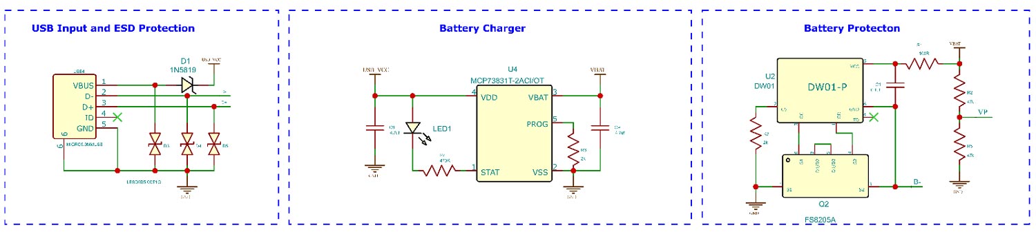
The micro-USB port is used for both charging as well as programming purposes. The power and data connections from the micro-USB port is connected to TVS ESD protection diodes. These diodes will protect the entire circuit from any ESD spikes on the USB input. The 5V from the USB port is then connected the input of MCP7383 1S Li ion battery charger. The out put from the charging IC is then fed to the protection circuit built around the DW01 IC and the FS8205 MOSFET. This protection circuit combination will protect the battery from over current discharges and deep discharge.
The power then passes through two LDOs. The main voltage regulator used in the circuit is the NCP167AMX330TBG from ON Semi. It can provide a maximum current of 700ma. The main advantage of using this chip is the size. The NCP167AMX comes in a 1mmx1mm 4-XDFN package. Which saves a lot of space. The second Low voltage regulator in the circuit is a XC620P182MR-G 1.8V LDO. This LDO is used for the MAX30102 Heart Rate sensor chip.
The power then passes through two LDOs. The main voltage regulator used in the circuit is the NCP167AMX330TBG from ON Semi. It can provide a maximum current of 700ma. The main advantage of using this chip is the size. The NCP167AMX comes in a 1mmx1mm 4-XDFN package. Which saves a lot of space. The second Low voltage regulator in the circuit is a XC620P182MR-G 1.8V LDO. This LDO is used for the MAX30102 Heart Rate sensor chip.
There are other specifiers you can use to get information in other format, for example: abbreviated month name (%b), abbreviated weekday name (%a), week number with the first Sunday as the first day of week one (%U)
We also show you an example, if you want to save information about time in variables. For example, if you want to save the hour into a variable called timeHour, create a char variable with a length of 3 characters (it must save the hour characters plus the terminating character). Then, copy the information about the hour that is on the timeinfo structure into the timeHour variable using the strftime() function.
Designing the PCB
.png)
.png)
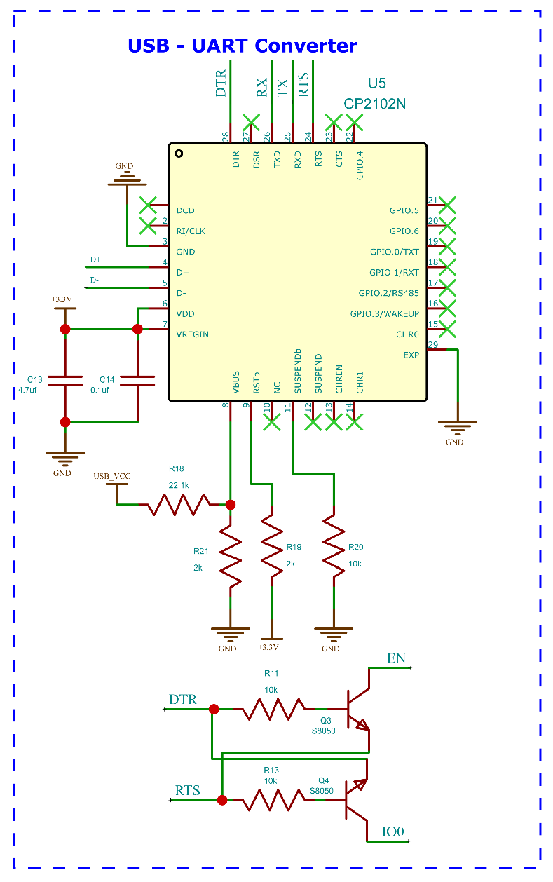
The next section in the USB UART controller. This section is designed around the CP2102N from Silicon Labs. It supports a maximum speed of 12Mbps. Minimal number of external components along with the small QFN-24 package makes it better choice among other controller chips in the same category. The auto reset circuit for the ESP32 is built around two S8050 NPN transistors. The transistors are connected to the DTR and RTS pins of CP2102 and EN and RST pins of ESP32. This enables us to program the ESP32 without the need of a reset button.
The MPU6050 accelerometer chip is used to detect motion. This feature enables us to wake the smart watch with a simple hand movement. Interrupt pin of the MPU6050 is connected to the GPIO14 of ESP32 controller. When a movement exceeding the set threshold is detected the MPU6050 will send an interrupt signal to the ESP32 to wake it from deep sleep.
For the PCB we have choose the two-board design. The top board contains the MCU along with display, UART controller, power circuitry, light sensor and the MPU6050 chip. The bottom bord contains HMC5883, LSM303, MAX30102, microSD slot and the vibration motor. The two board are connected using a 10 pin FPC cable with a pitch of 0.5mm.
After inserting your network credentials and modifying the variables to change your timezone and daylight saving time, you can test the example.
Upload the code your ESP32 board. Make sure you have the right board and COM port selected. After uploading the code, press the ESP32 button
Programming
.png)
.png)
.png)
A timestamp is a time stamp that indicates an event’s precise date and time. It is a series of numbers representing the event’s date and time.
Epoch time, or Unix time, is a time reference commonly used in computer systems. It represents the number of seconds elapsed since January 1st, 1970, at midnight UTC . This reference date is often used as a starting point to calculate the date and time of an event using a timestamp. For example, if a timestamp is equal to 1601054743, it means that it is the number of seconds elapsed from January 1, 1970, until the event in question (i.e., Tuesday, December 13, 2022, at 10h12m25s). Its use facilitates the calculations related to the date and the hour in the computer systems.
Take into account the time difference (UTC, GMT)
To have the right time, we must consider the local time difference. To do this, we reference the UTC or GMT corresponding to the time difference +0. We then adjust this value according to the local time zone and possibly an additional summer/winter time. For France, it is +1 in winter and +2 in summer.
#include <WiFi.h>
#include "time.h"

const char* ssid = "upesy-ap"; // Name of the Wi-Fi box
const char* password = "cupcakes"; // MDP of the Wi-Fi box

const char* ntpServer = "pool.ntp.org";
const long  gmtOffset_sec = 3600 * 1;
const int   daylightOffset_sec = 3600 * 0;

void setup() {
  Serial.begin(115200);
  delay(1000);

  WiFi.mode(WIFI_STA); // Optional
  WiFi.begin(ssid, password);
  Serial.println("\nConnecting");

  while (WiFi.status() != WL_CONNECTED) {
    Serial.print(".");
    delay(100);
  }

  Serial.println("\nConnected to the WiFi network");
  Serial.print("Local ESP32 IP: ");
  Serial.println(WiFi.localIP());

  // We configure the NTP server
  configTime(gmtOffset_sec, daylightOffset_sec, ntpServer);
}

void loop() {
  struct tm timeinfo;
  if (!getLocalTime(&timeinfo)) {
    Serial.println("Failed to obtain time");
  }
  Serial.println(&timeinfo, "%A, %B %d %Y %H:%M:%S");
  delay(1000);
}
It can be broken down into three parts:
- Wi-Fi configuration and connection
- The configuration of the NTP server
- Retrieving the date every second from the NTP server
Note
If you are in summer, you will have to put a daylightOffset_sec = 3600; to have daylight saving time
The loop function will call all the mains functions periodically, that included button_tick, watchtask and the game functions. The button_tick function is responsible for the key press detection and distinguish between shot press and long press. The watchtask function is responsible for all the major functions that includes watch face display, heart rate monitoring, digital compass, menu handling and all the settings and navigations. In the meantime, the game function will handles the flappy bird game, the included in the watch OS.
As mentioned earlier the watchtask will handle most the tasks related to the smart watch. This function will check for if the brightness settings and will adjust the backlight PWM accordingly. It will also check for the screen time out settings and will put the ESP32 to deep sleep accordingly. All the sub functions will be called accordingly based on the current active task. We have used gpio_deep_sleep_hold_en function along with the gpio_hold_en function to keep the backlight pin active low during the deep sleep. Without these functions the GPIO will be released from any set states, and it will affect the backlight control.
void watchtask() {
  if (pressstate == 1 && digitalRead(0) == 1) {
    pressstate = 0;
  }
  if (AutoBright == 0) {
    unsigned int lv = constrain(lightMeter.readLightLevel(), 50, 500);
    analogWrite(LCD_BACKLIGHT, lv / 2);
    Serial.print("Light");
    Serial.println(lv / 2);
  }
  if (Autoscreen != 0 && millis() - lastwake > Autoscreen * 60000) {
    analogWrite(LCD_BACKLIGHT, 0);
    delay(1000);
    tft.fillScreen(colour7);
    gpio_deep_sleep_hold_en();
    gpio_hold_en((gpio_num_t)LCD_BACKLIGHT);
    esp_deep_sleep_start();
Editing in Easyeda
.png)
.png)
.png)
NTP time server implementation using NEO-6MV2 GPS module as a reference clock. Originally based on with heavy modifications to work on espressif ESP32 platform, and to use the global positioning system (GPS) instead of the russian GLONASS. The GPS is re-configured for 115200 baud and 1 PPS with 100ms pulse duration at run-time. The rewrite also incorporates a forked version of the well-know "time.h" arduino library modified to provide microsecond resolution and the ability to use a PPS clock input signal. Specifically, the code is designed to run on an "olimex ESP32-GATEWAY" development board having an on-board RJ45 100MBit ethernet jack, but can easily be adapted to work with other ESP32 boards using external ethernet connectivity (or WiFi connection). Also, a cheap 128x64 0.96" Oled LCD is used for displaying basic information. Average precision was measured (by comparison to known-good time sources) with 1 ms, or 0.001 seconds (the smallest reliable time unit this GPS module can deliver) offset compared to e.g. the PTB NTP server ptbtime1.ptb.de, or other official time sources, provided the offset is adjusted accordingly using #define TIME_OFFSET_USEC. The NTP server uses DHCP for IPv4 address retrieval, and replies to "simple mode" NTP queries by sending packets with "stratum 1" flag (testable with w32time.exe on windows: w32tm.exe /stripchart /computer:<IP-of-NTP-server> /period:1 /samples:3 /packetinfo, or with ntpdate on linux: ntpdate -q <your-NTP-server-IP>). GPS reception is good even indoors when using an external GPS antenna instead of the small ceramic antenna shipping with commonly sold GY-NEO6MV2 modules. Precision can be further improved when using one of the more expensive "NEO7T"/"NEO8T" modules (note the "T"), which allow for fixed location precision timing modes to be used, giving a PPS pulse with superior accuracy.
Used Hardware
- Microcontroller: Olimex ESP32-Gateway
- GPS time reference: GY-NEO6MV2
- OLED: cheap 0.96" OLED
- Antenna: active GPS antenna with 5m wire
Wiring
GPS <-> ESP32
-----------------
GND --> GND
Tx  --> PIN10 (Rx)
Rx  --> PIN32 (Tx)
VCC --> +3.3V
LED/PPS output --> 600 ohm resistor --> PIN36
(this needs some fine soldering with thin wire to attach PIN36 to the trace running to the GPS module LED)
Ordering PCB From JLCPCB


This project contains PCB and which was made with the help of JLCPCB
JLCPCB has upgraded the via-in-pad process of all 6-20 layer PCBs for free and provides free ENIG to make PCB products more stable and reliable. It is worth mentioning that due to large-scale production capabilities, JLCPCB is able to reduce the cost, allowing everyone to truly enjoy the benefits of the JLCPCB advanced fabrication. Here at JLCPCB, you can also get 1-8 layer PCBs at only $2
Go to JLCPCB website and create a free account.
Register and Login using Google Account is also possible.
Step 2 – Upload Gerber File
Once you have successfully created an account, Click on “Quote Now” and upload your Gerber File.
Gerber File contains information about your PCB such as PCB layout information, Layer information, spacing information, tracks to name a few.
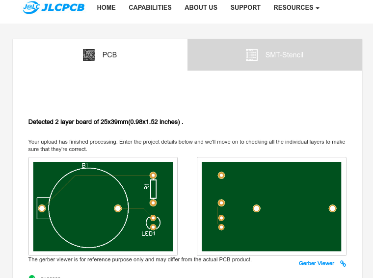
Step 3 – Preview the File
Once the Gerber file is uploaded, it will show you a preview of your circuit board.
Make sure this is the PCB Layout of the board you want.
Step 4 – Choose Necessary PCB Options
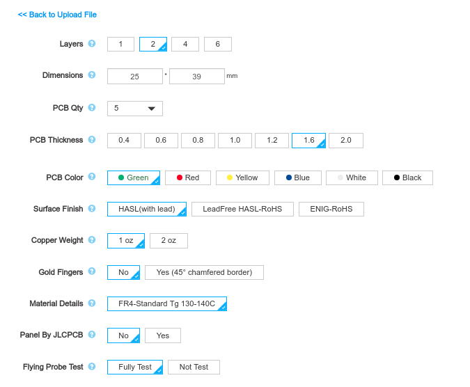
Below the PCB preview, you will see so many options such as PCB Quantity, Texture, Thickness, Color etc. Choose all that are necessary for you.
Conclusion
.png)
In conclusion, the NTP server plays a crucial role in obtaining the current time and date for our ESP32 development board, which is connected to a stable WIFI connection. By querying the NTP server, we ensure that our ESP32 device has access to accurate and synchronized time information. This enables us to display the correct time to users, log events with precise timestamps, and coordinate activities with other devices in a networked environment. The NTP server’s ability to provide highly accurate time data enhances the reliability and functionality of our ESP32 projects, making it an essential component for accurate timekeeping.