Email Alerts of Vibration and Temperature Using Node-RED
by rjrajbir in Circuits > Sensors
3322 Views, 1 Favorites, 0 Comments
Email Alerts of Vibration and Temperature Using Node-RED
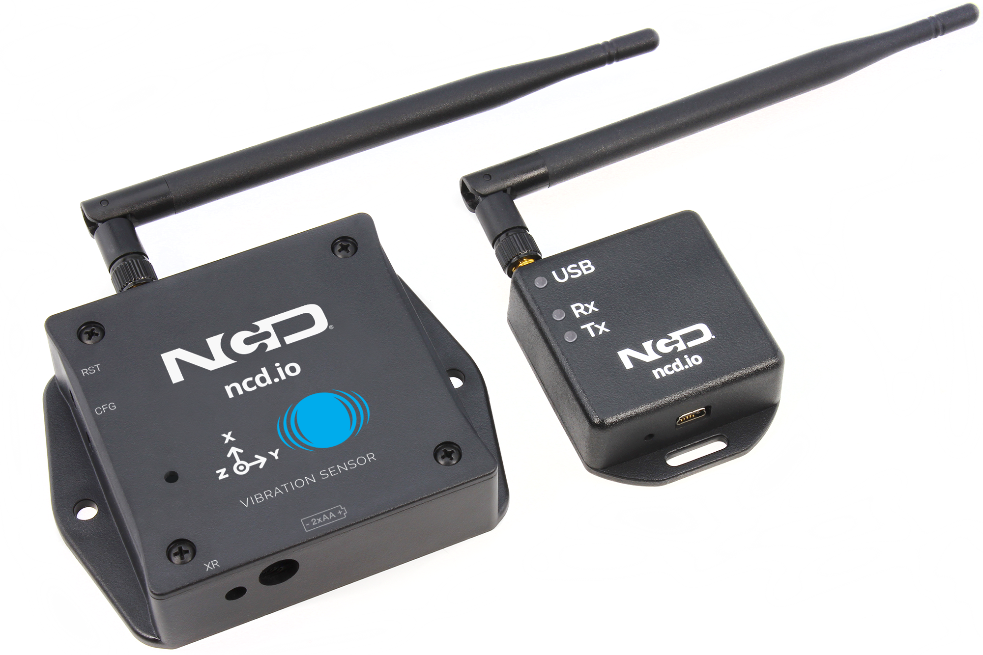
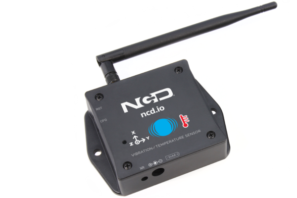
Introducing NCD’s Long Range IoT Industrial wireless vibration and temperature sensor, boasting up to a 2-mile range the use of a wireless mesh networking structure. Incorporating a precision 16-bit vibration and temperature sensor, this device transmits incredibly accurate vibration and temperature records at consumer-described durations.
Hardware and Software Required
Setting Up Node-red
Now that you have sensors running, we need a way to do something useful with that data.
- First of all, you'll have to install Node-Red.
- Once that’s done, you’ll need to enter your command line, or Power Shell for Windows users, navigate to the directory Node-RED is installed in.
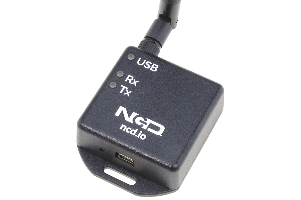
- Now type “npm i ncd-red-wireless node-red-dashboard“. This will install the nodes required to receive data from your wireless sensors and you can start Node-RED once this is done.
- To start node server write node-red in the command prompt or terminal and press enter.
Steps to Create the Flow
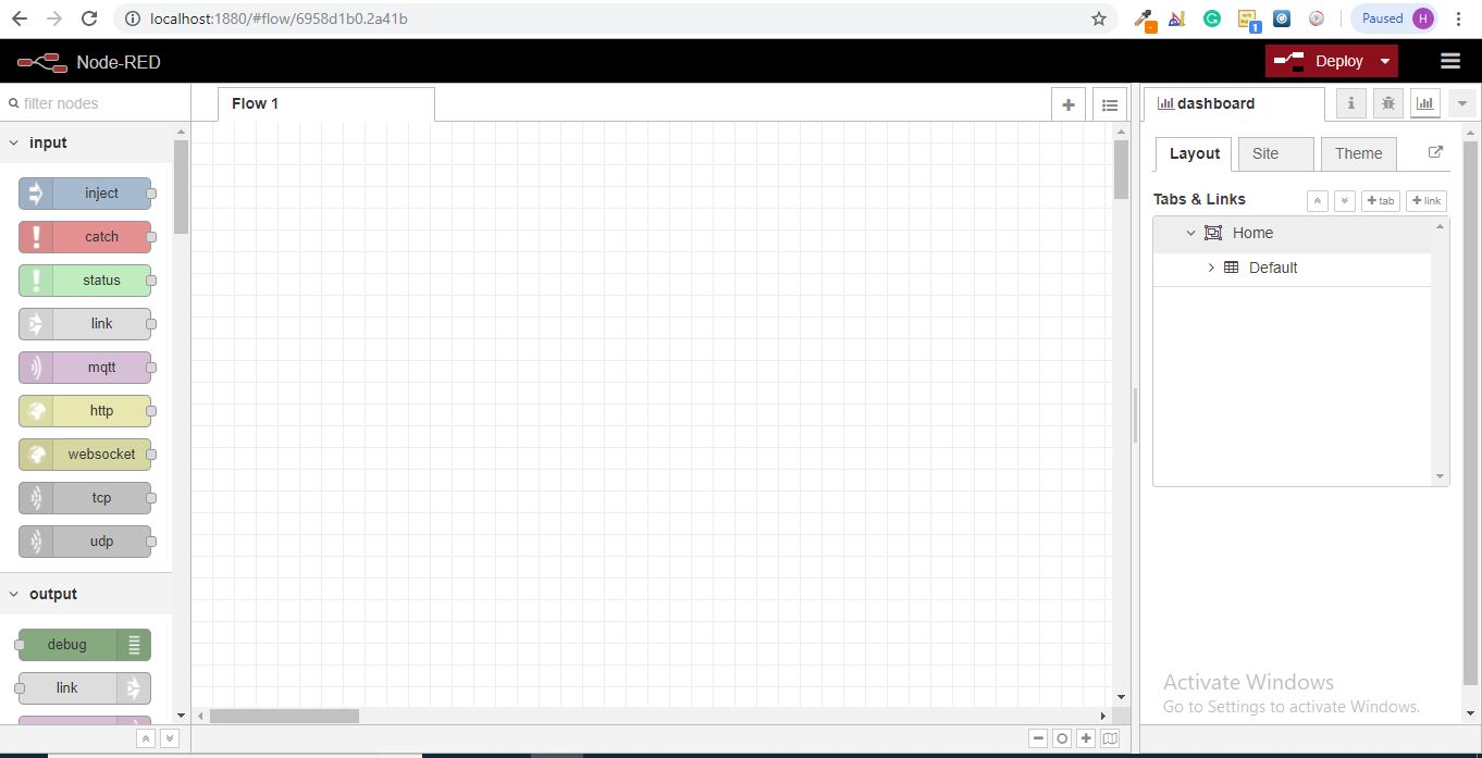
At this point you’ll be viewing a large blank flow with a long list of nodes on the left-hand side, this sidebar is called the palette.
Go Ahead and Drag a Wireless Gateway Node Over to Your Flow Canvas to Get Started.
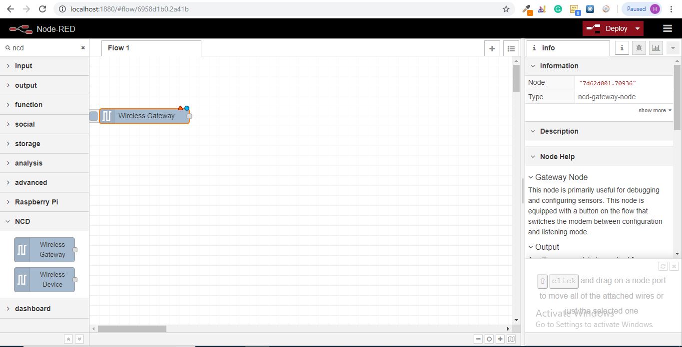
ncd-red-wireless Provides the nodes that manage the serial connection, parse incoming sensor data, filter it by specific parameters, and allow you to configure the wireless sensors.
Finding Your Wireless Sensors
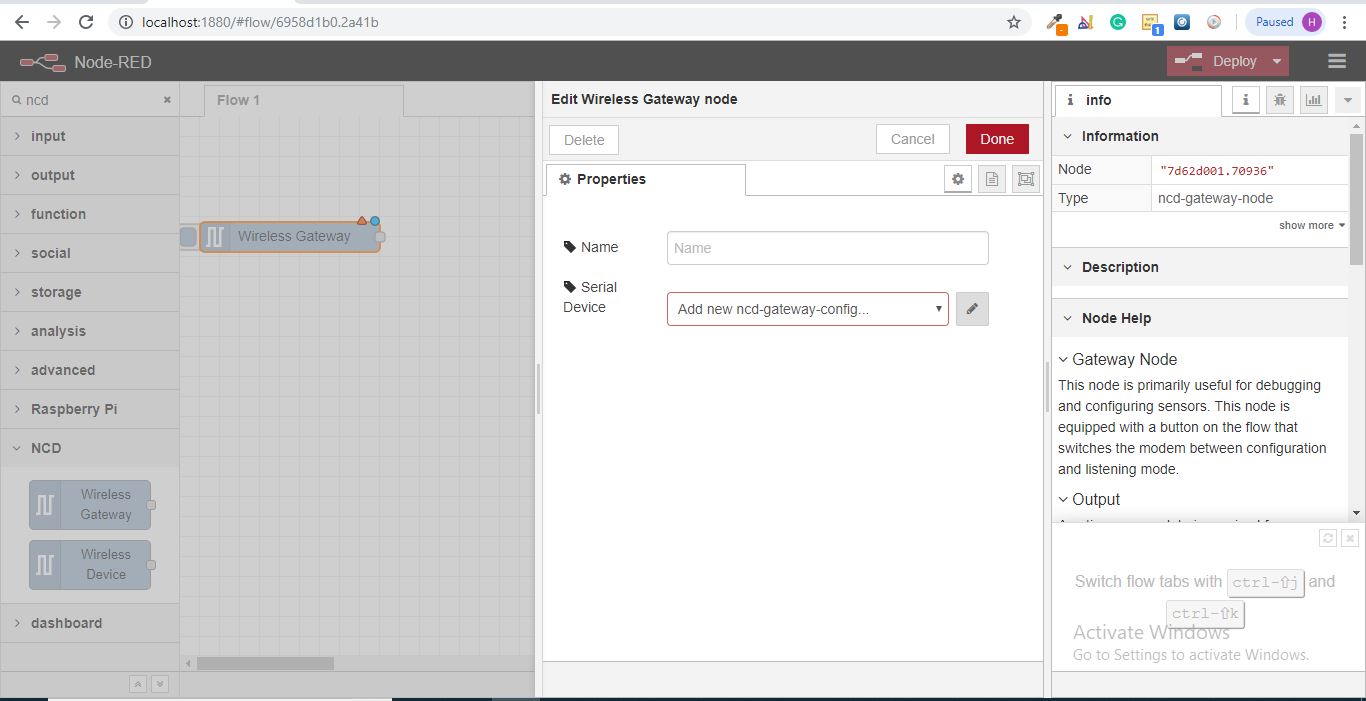
When you’ve delivered the node you’ll be able to view the info tab, which contains records about the node’s capability, this tab is well-populated for maximum node-red packages and consists of treasured statistics, often you will now not want to view any other documentation outdoor of the info tab, so hold it in thoughts even as you're building your flows when you have a question approximately how a node works. The next element we want to do is configure the node, when you first add it you’ll note that there is a small triangle at the top right corner next to a blue dot, the triangle indicates that the node wishes extra configuration, the blue dot indicates that the node has no longer but been deployed as part of the flow.
- Double click on the node to open up the configuration options.
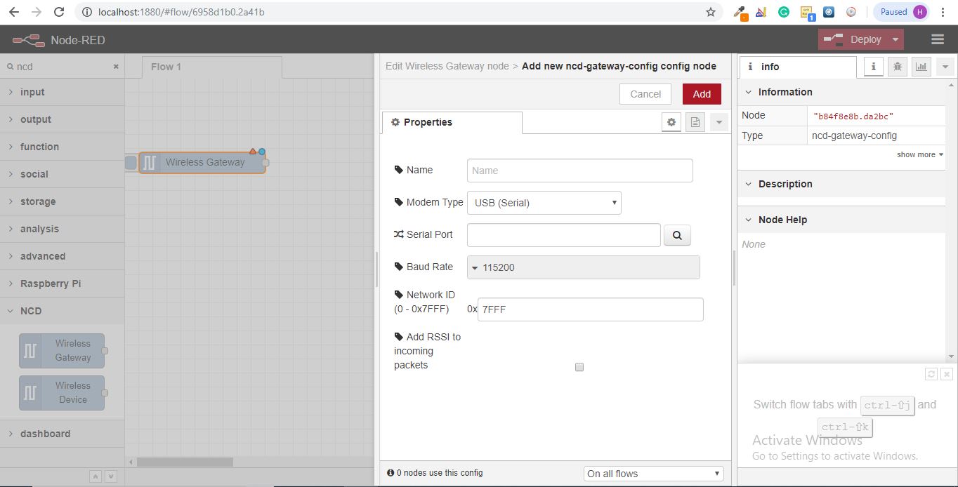
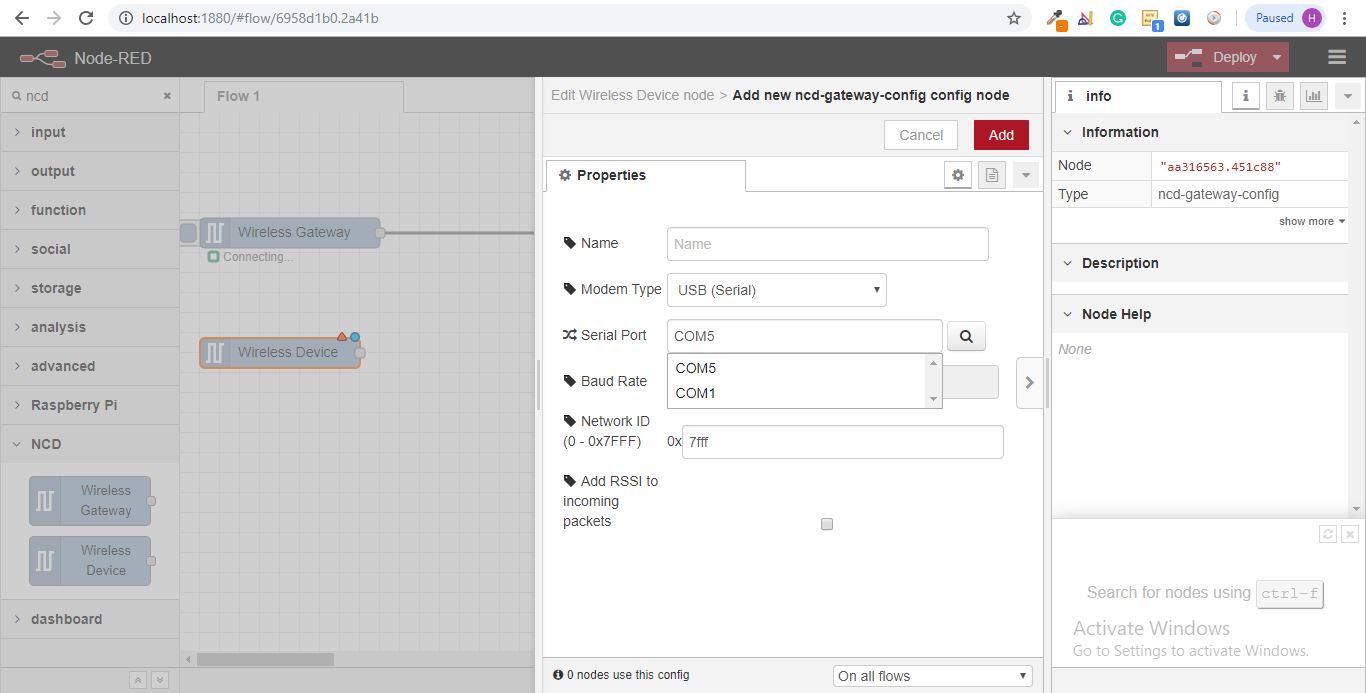
- Click on the pencil icon next to the Serial Device field to configure your USB router, this will open a second configuration panel that only has a few options.
Click on the Magnifying Glass Next to the Serial Port Field and Select the Port That Corresponds With Your Router, Then Click the “Add” Button on Top.
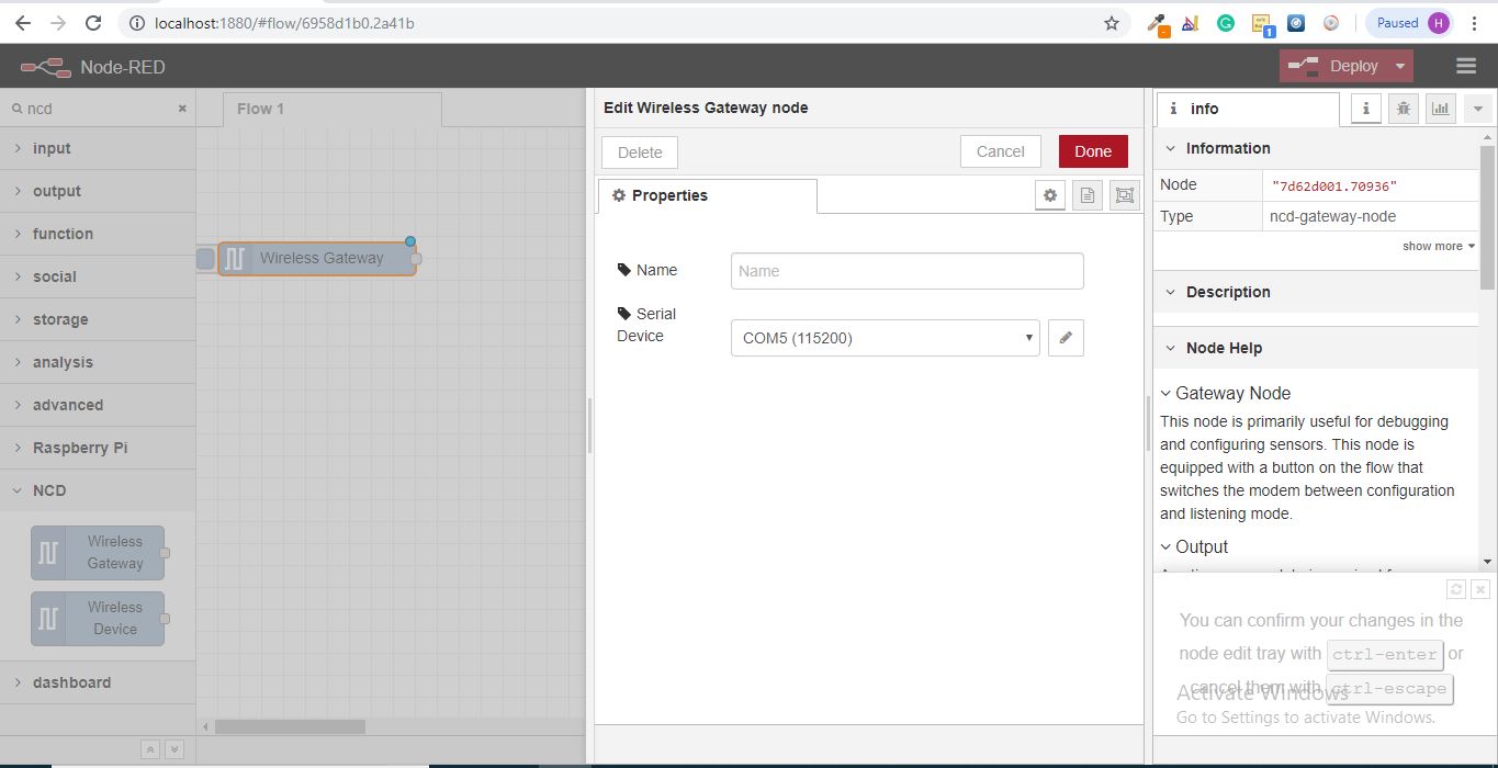
Serial Device Field Will Now Be Populated Based on That Selection, and You Can Click “Done”, You Now Have Direct Access to Your Wireless Sensors! to View the Data Coming In.
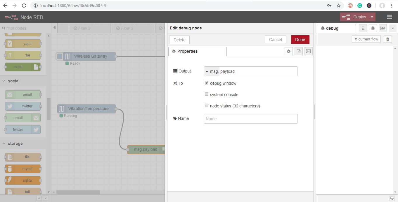
Now Go Back to Your Palette and Type “debug” Into the Search Field at the Top, Grab One of These Nodes and Drag It to the Right of Your Wireless Gateway
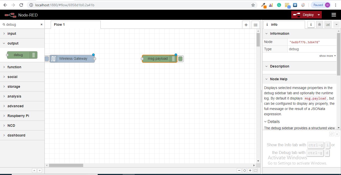
Double Click on It and Change “msg.” to “complete Msg Object” Click Done
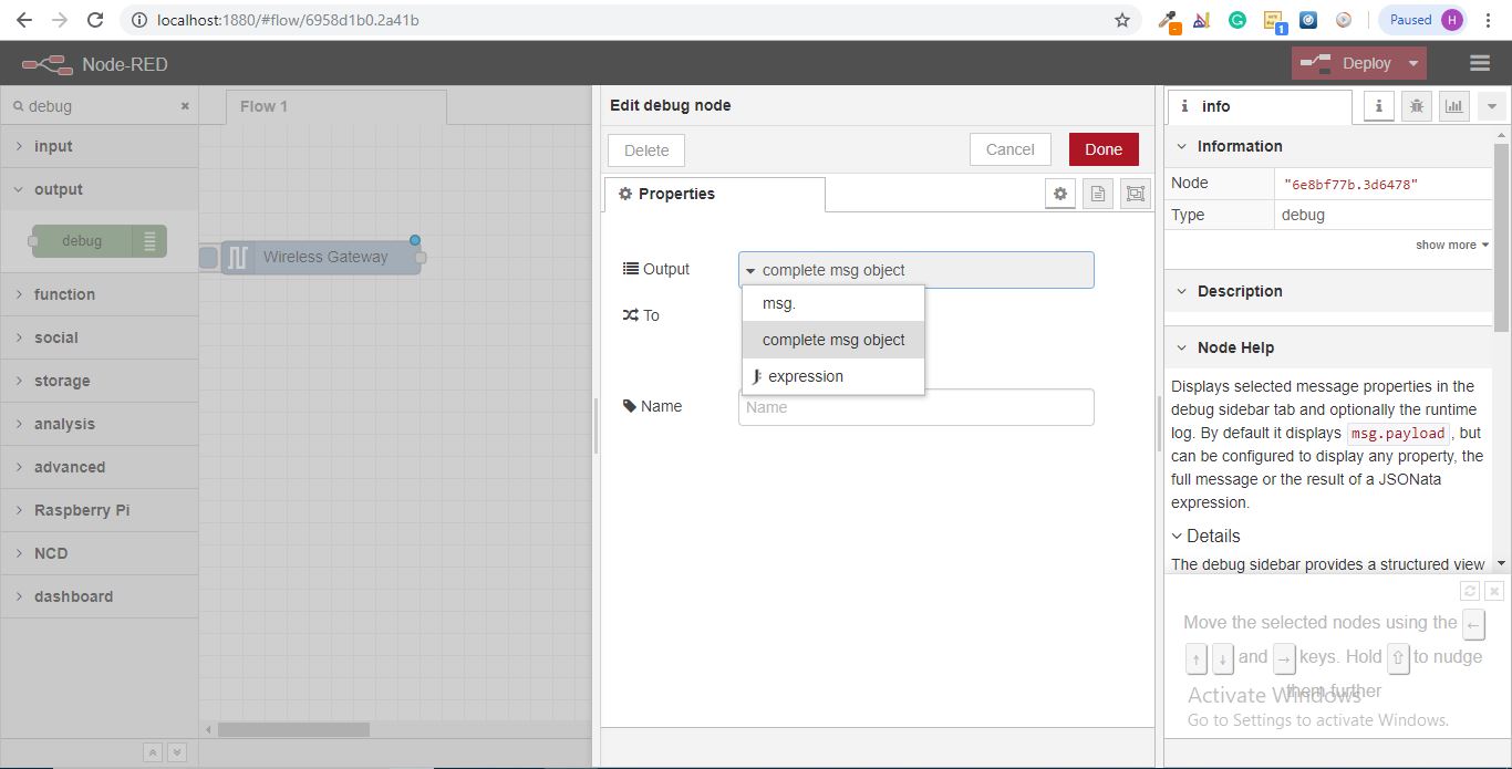
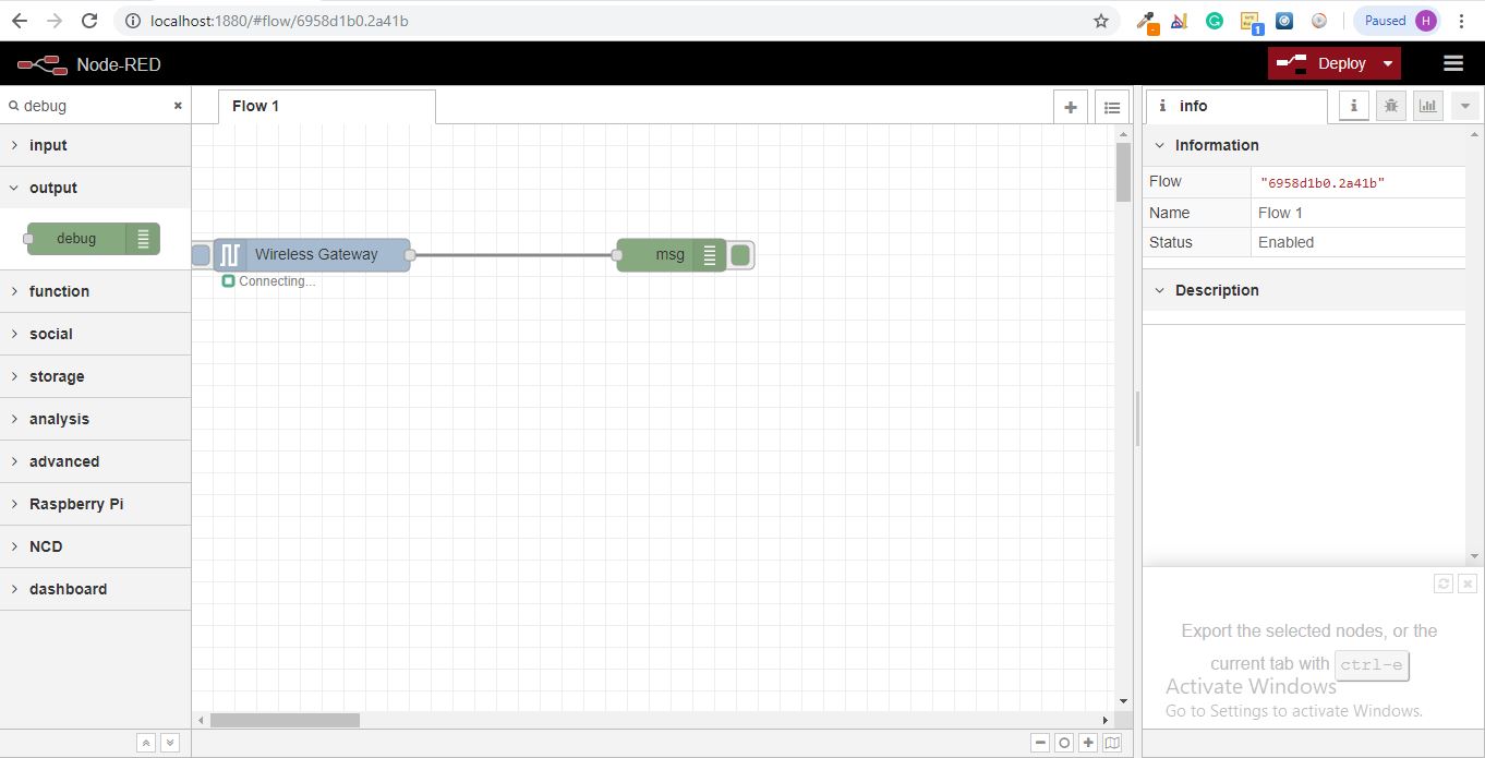
Now Draw a Line Between the Two Nodes, and Click “Deploy” on the Top Right of the Window..
Working With the Data
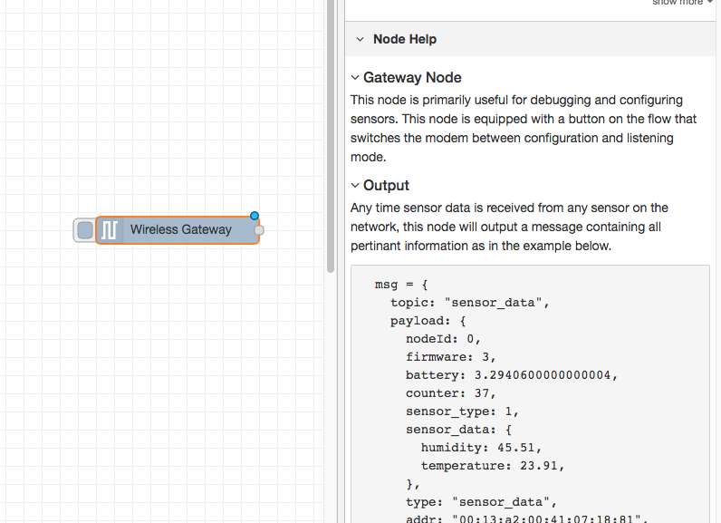
Now out of your wireless sensors data is gathered and it is output to the “debug” tab, this "debug tab" is placed within the right sidebar subsequent to the information tab. To see the information is available to hit the reset button. In node-red records is surpassed among nodes in a json packet. When the msg object comes into the debug tab you may make bigger it to view the overall list of information that comes with it. This is extraordinarily useful in case you need to quickly see which sensors are checking in. The other issue this node gives is an easy way to interchange your router to the network identity that devices in configuration mode document on, simply hit the button on the left of the node and the tool will switch to the configuration network, hit it once more to return it to listening mode. Once we get the wi-fi tool nodes set up, they may be set to routinely configure a sensor whilst it enters configuration mode, so it’s always available to maintain such gateway nodes present at the flow for speedy configuring a device.
Adding the Wireless Sensors:
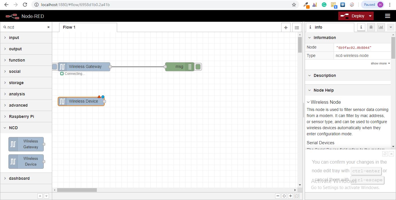
We need to separate wireless sensor records domestically in order that we are able to display it, we could use a switch node to split out the messages from the gateway based totally on the mac address with or sensor type, but as I referred to, the wireless nodes truly incorporate extra functionality for configuring the sensors, so we’ll start with them to give you an extra entire image of how those structures can work. In case you haven’t already seen packets coming in from both of your sensors, cross in advance and hit the reset button on the only that hasn’t started. While a sensor assessment in through any serial device configuration node, the mac address and kind of sensor is cached in a pool so we are able to quickly find it for the duration of this next step.
- Grab a Wireless Node from the palette and drag it onto the flow, double click on it to get it configured
Select the Serial Device From the Drop Down That You Used for the Wireless Gateway, Now Click the Magnifying Glass Next to “Mac Address” and Select One of the Available Options.
Click Done
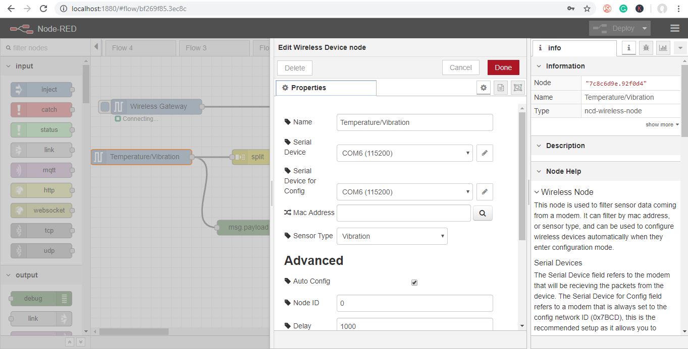
You’ll notice this automatically sets the sensor type for you, you can also give it a name to make it easier to identify. As noted in the info tab, the Serial Device for Config field is optional, and we won’t worry about it right now. The node you have just added effectively works as a filter on incoming sensor data, only passing through data for the mac address, or sensor type if no mac address is present.
Now Go Back to Your Palette and Type “debug” Into the Search Field at the Top, Grab One of These Nodes and Drag It to the Right of Your Wireless Gateway
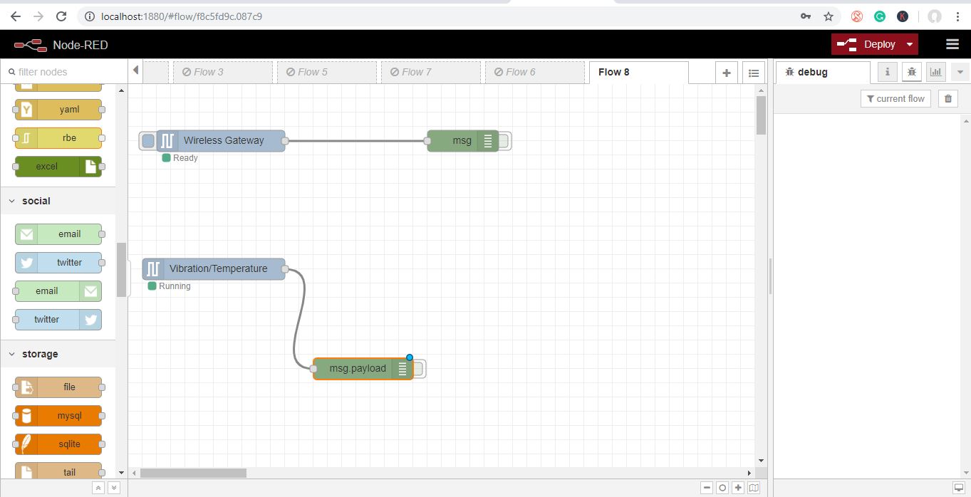
Double Click on It and Click Done
Adding Function Nodes
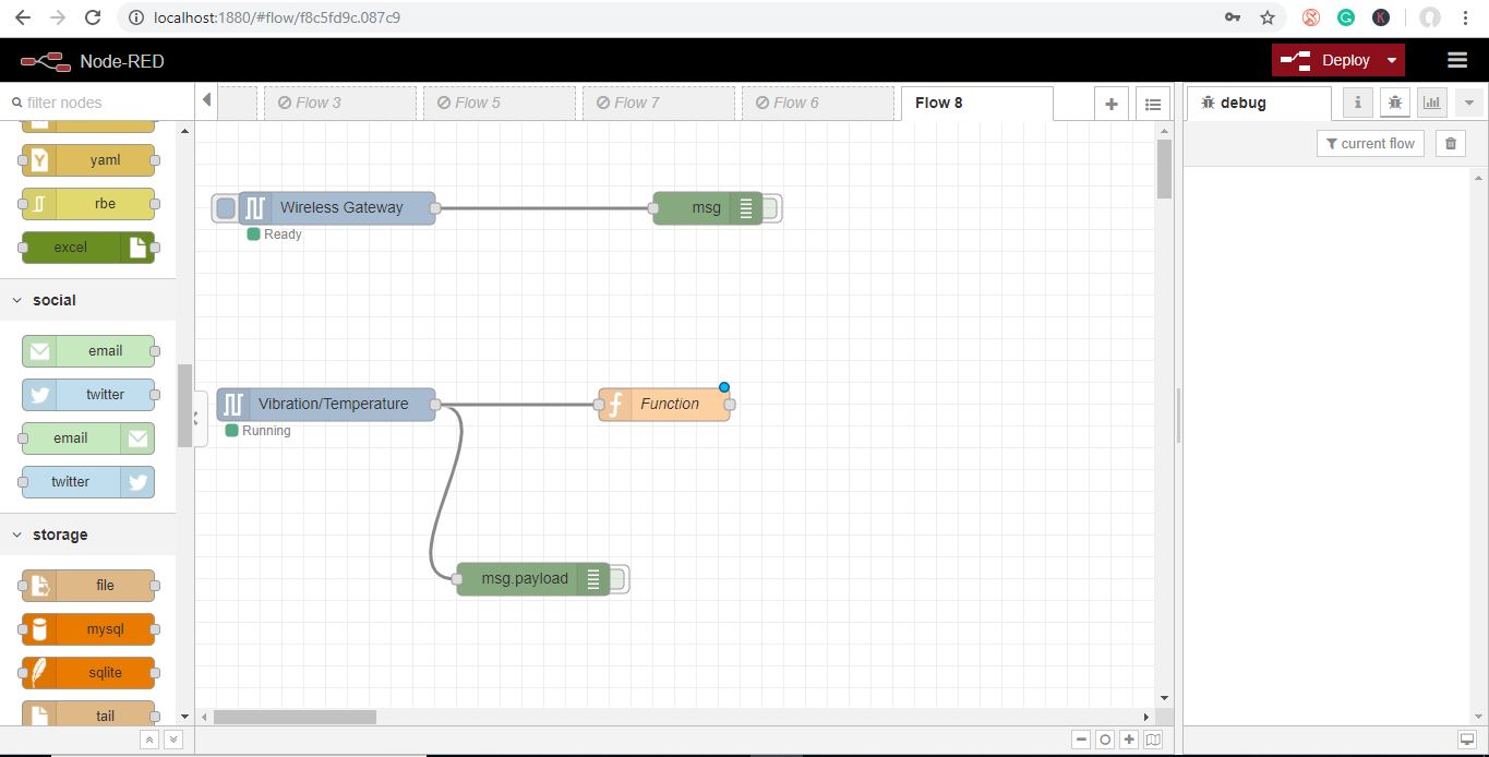
The function node is used to run JavaScript code against the msg object. The function node accepts a msg object as input and can return 0 or more message objects as output. This message object must have a payload property (msg.payload) and usually has other properties depending on the proceeding nodes.
- Now grab a “function” node from the palette, and place it to the right of the Vib/Temp node.
Double Click on the Node to Open Up the Configuration Options.
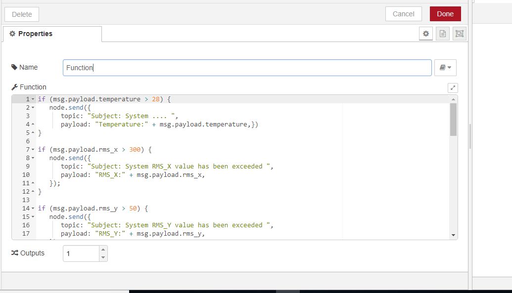
Here you have to write little javascript code to create a condition, so at a particular value, an email alert will be sent to the respective email id.
You can edit values as our own.
if (msg.payload.temperature > 28) { node.send({ topic: "Subject: System .... ", payload: "Temperature:" + msg.payload.temperature,})}if (msg.payload.rms_x > 300) { node.send({ topic: "Subject: System RMS_X value has been exceeded ", payload: "RMS_X:" + msg.payload.rms_x, });} if (msg.payload.rms_y > 50) { node.send({ topic: "Subject: System RMS_Y value has been exceeded ", payload: "RMS_Y:" + msg.payload.rms_y, });} if (msg.payload.rms_z > 100) { node.send({ topic: "Subject: System RMS_Z value has been exceeded ", payload: "RMS_Z:" + msg.payload.rms_z, }); }if (msg.payload.max_x > 500) { node.send({ topic: "Subject: System MAX_X value has been exceeded ", payload: "MAX_X:" + msg.payload.max_x, });}if (msg.payload.max_y > 50) { node.send({ topic: "Subject: System MAX_Y value has been exceeded ", payload: "MAX_Y:" + msg.payload.max_y, });}if (msg.payload.max_z > 0) { node.send({ topic: "Subject: System RMS_x value has been exceeded ", payload: "MAX_Z:" + msg.payload.max_z, });}if (msg.payload.min_x < 0) { node.send({ topic: "Subject: System MIN_X value has been exceeded ", payload: "MIN_X:" + msg.payload.min_x, });}if (msg.payload.min_y < 0) { node.send({ topic: "Subject: System min_y value has been exceeded ", payload: "MIN_Y:" + msg.payload.min_y, });}if (msg.payload.min_z < (-150)) { node.send({ topic: "Subject: System MIN_Z value has been exceeded ", payload: "MIN_Z:" + msg.payload.rms_x, });} return;
Now Grab an Output Email Node From the Palette and Place It to the Right of the Vibration and Temperature Node.
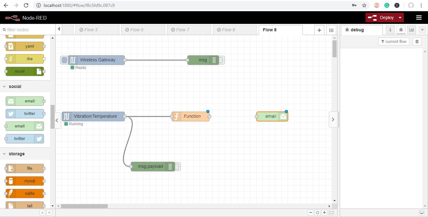
The Email node provides both input and output of emails.
Now Double Click on It and Open Up the Email Edit Node
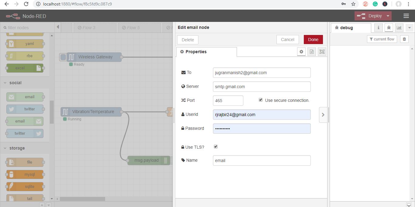
- Now add “email-id” of the person at first field whom you want to send the email alerts and then also add “email-id and password” of that person from where you want to send alerts as shown in the picture below and click done.
Now Draw All the Wires and Click Deploy As Shown in the Picture.
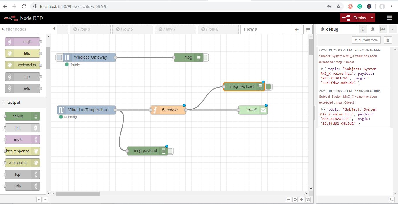
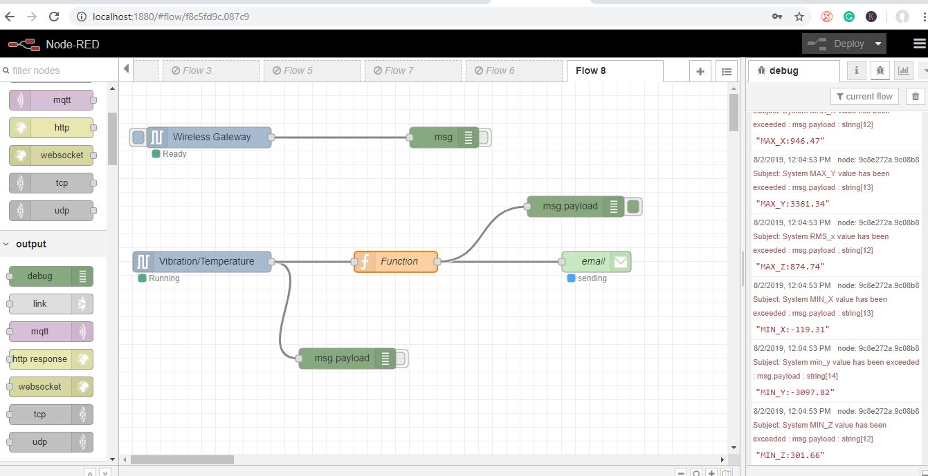
Output
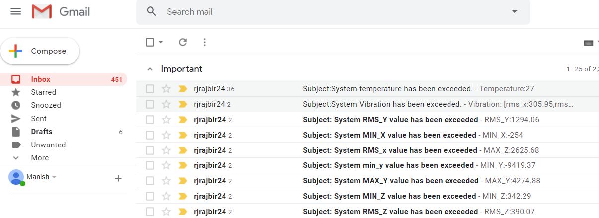
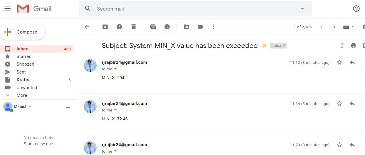
Now you will see emails are sending. You can also check on the respective email ID.
Node-RED Flow
Downloads
There Is Another Method, in Which You Can Send Vibration and Temperature Emails Separately.
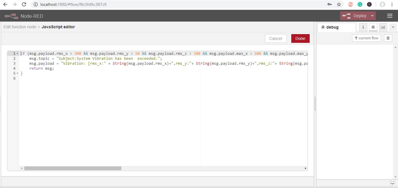
The steps are the same up to function node
- Now double click on the function node to edit the function node. Now the code for this function node is.
if (msg.payload.rms_x > 300 && msg.payload.rms_y > 50 && msg.payload.rms_z > 100 && msg.payload.max_x > 500 && msg.payload.max_y > 50 && msg.payload.max_z > 0 && msg.payload.min_x < 0 && msg.payload.min_y < 0 && msg.payload.min_z < -150) { msg.topic = "Subject:System Vibration has been exceeded."; msg.payload = "Vibration: [rms_x:" + String(msg.payload.rms_x)+",rms_y:"+ String(msg.payload.rms_y)+",rms_z:"+ String(msg.payload.rms_z)+",max_x:"+ String(msg.payload.max_x)+",max_y:"+ String(msg.payload.max_y)+",max_z:"+ String(msg.payload.max_z)+",min_x:"+ String(msg.payload.min_x)+",min_y:"+ String(msg.payload.min_y)+",min_z:"+ String(msg.payload.min_z)+"]"; return msg;}Now Grab Another Node From the Palette for Temperature Values
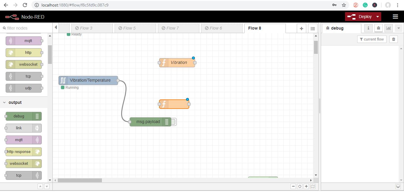
Now Double Click on the Function Node to Edit the Function Node.
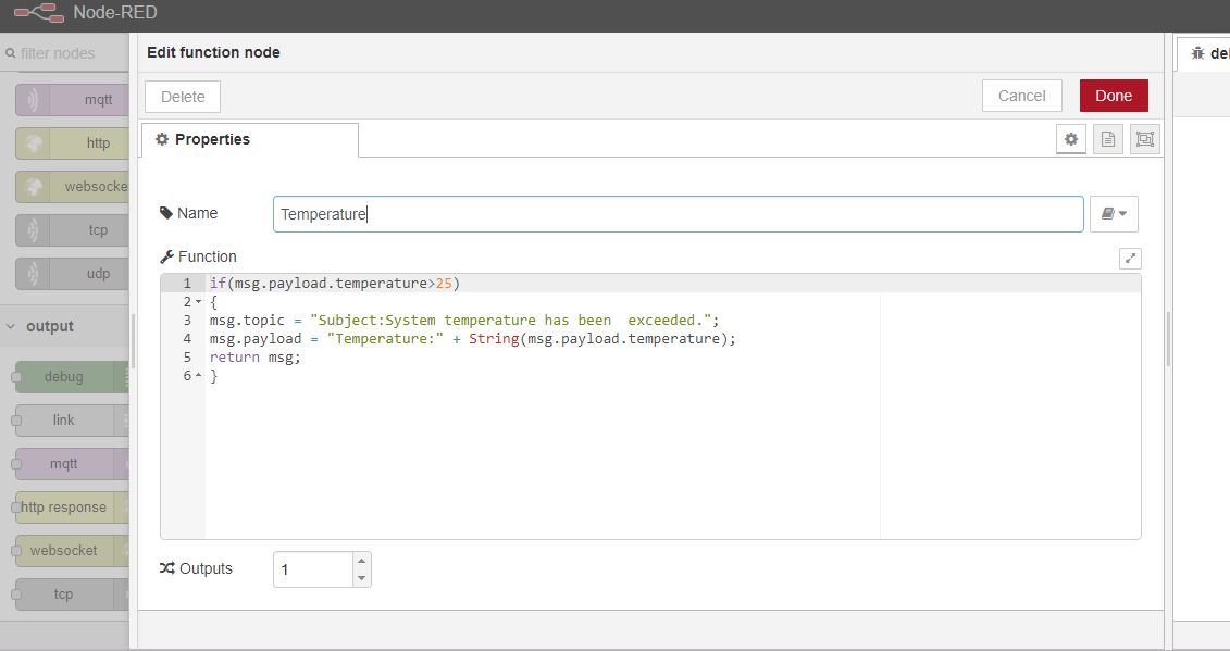
Now Grab an Email Node From the Palette
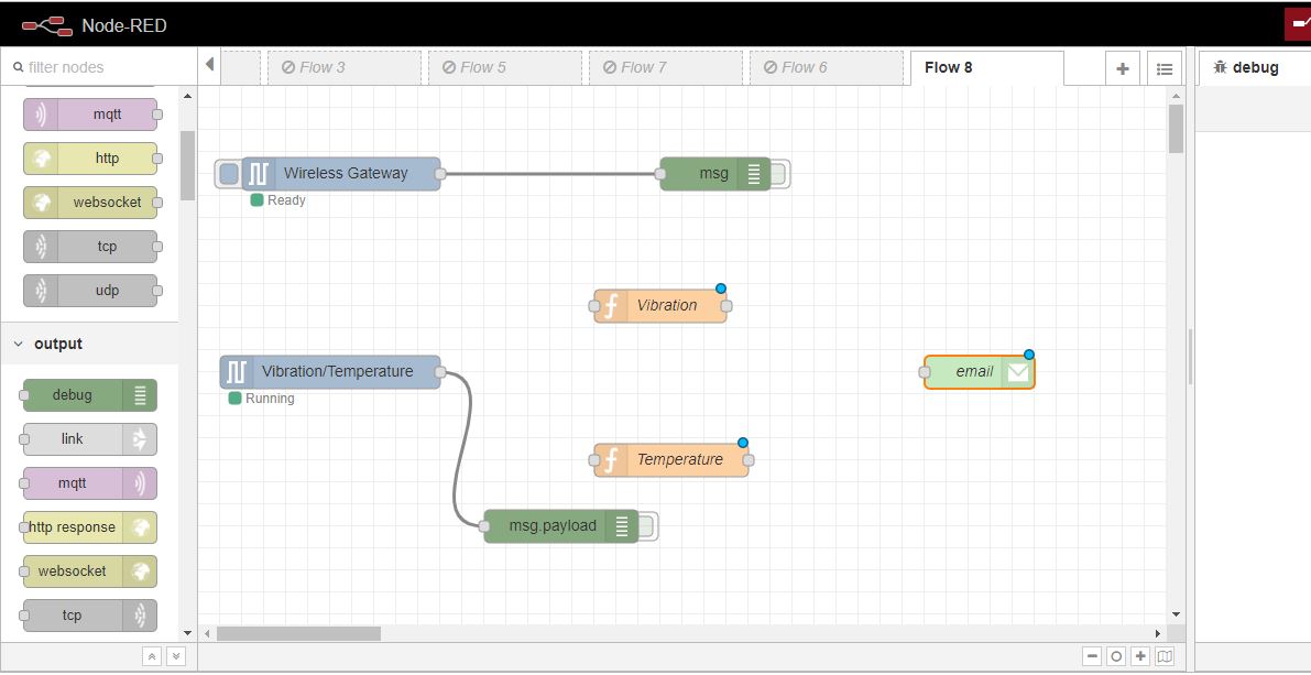
Now edit it like, you have done above.
Connect All the Wires Then Click the “Deploy” Button.
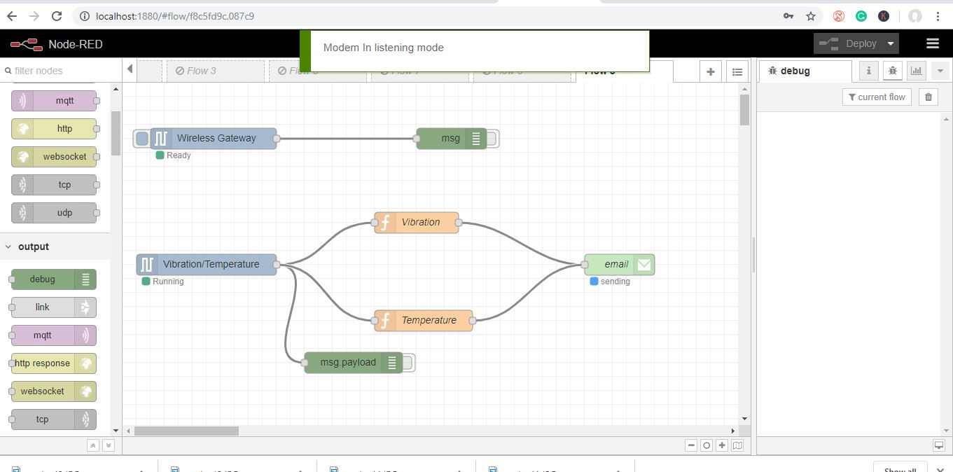
Output
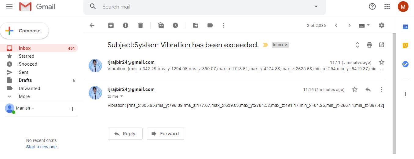
This is the output of the vibration value.
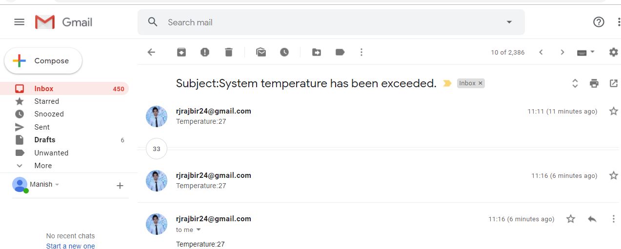
This Is the Email Alert of Temperature Value.
If You See No Emails Are Sending or “sending Failed," Go to Google Account and You’ll See Security Issue Find.
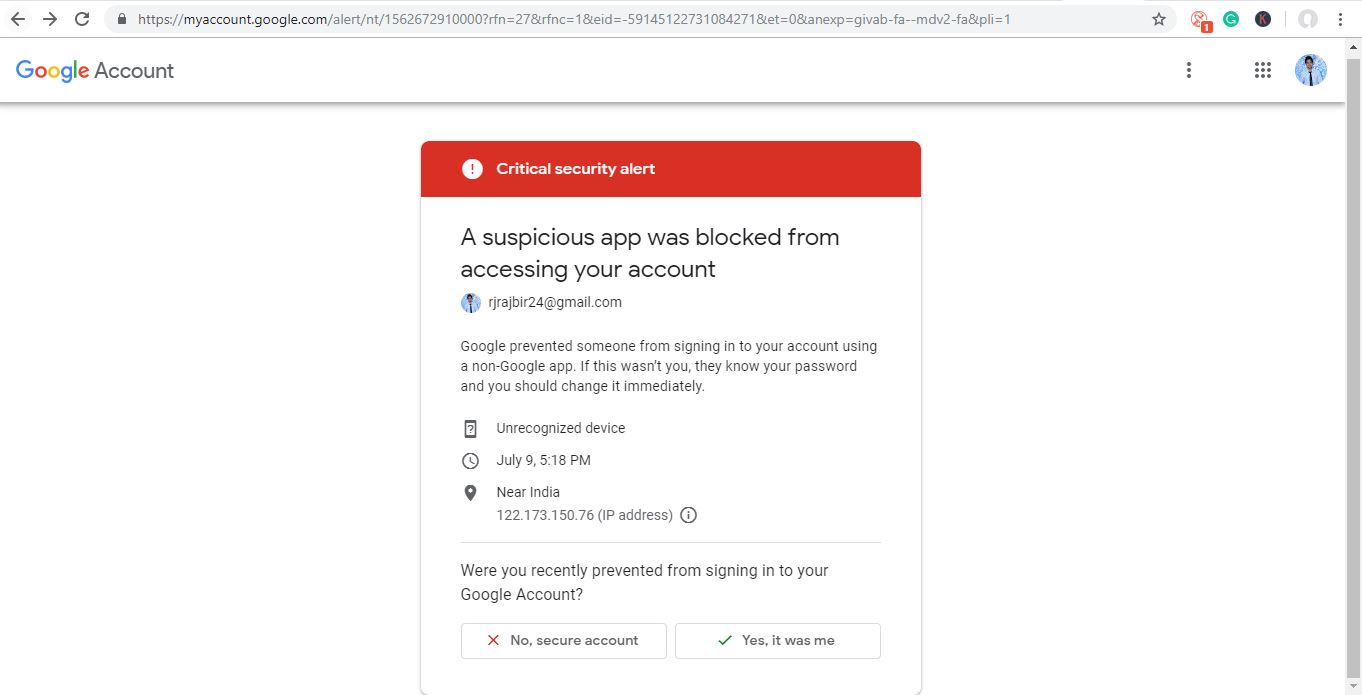
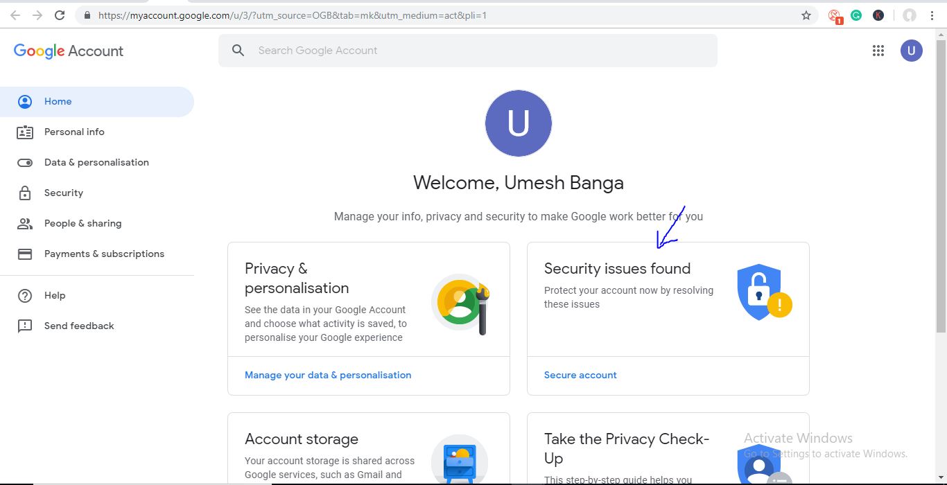
Click on It and Allow “Third-party Access” to the Apps As Shown in In the Figure.
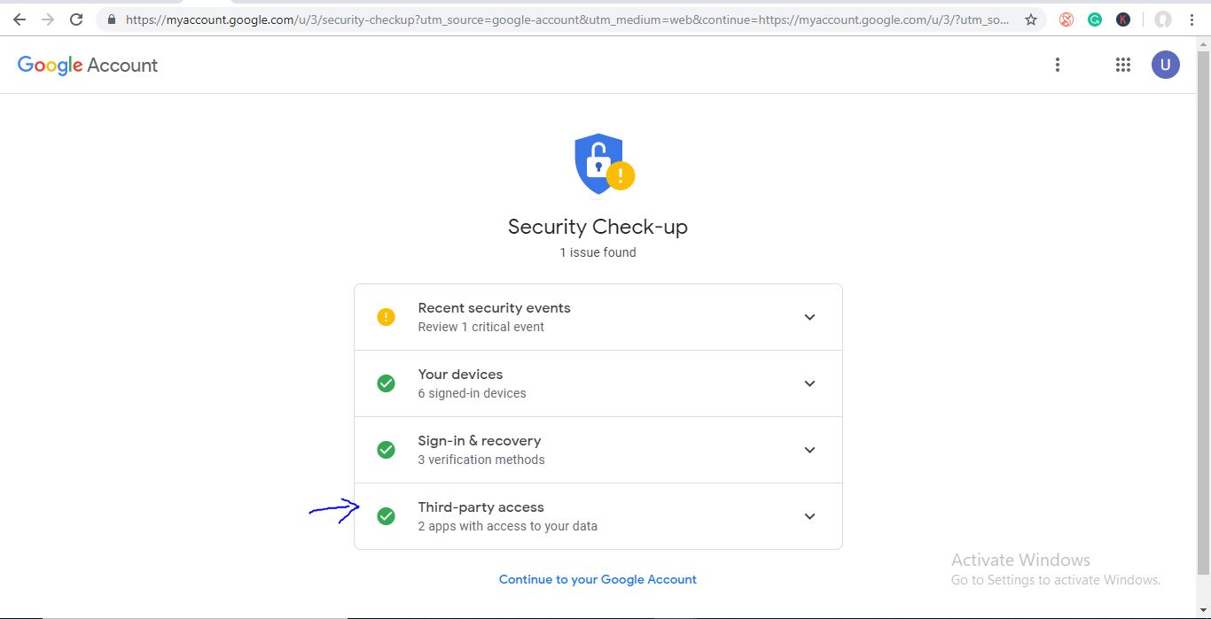
If you still not getting emails, you can also check your spam folder.