Elevator LEDs
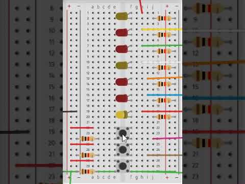
My students have been working on creating an elevator with their VEX Robotics kits. A lot of them have been struggling with some of the bonus challenges I have included into their assignment. This inspired me to find a way to do a similar activity for my graduate class at Saint Catherine University, Physical Computing. I do not have the same structural equipment that I do have for our robotics kits, but I found a way to simulate the challenge that the students in my class are doing by using LED's to simulate an elevator rising and lowering.
In my sketch, the yellow LEDs represent each floor (ground, second, and third floor). The red LEDs show the elevator rising or lowering to each floor. The elevator will start out on the ground floor and wait for the second floor button or for the third floor button to be pressed. When one of those buttons is pressed the elevator will go to that floor, pause for 2 seconds and return the ground floor.
Platform: Arduino UNO
Language: C++
User Level: Beginner-Advanced (Advanced users should try the Bonus Challenges)
List of Materials and Equipment:
- 1 Arduino Uno
- 3 Push Buttons
- 3 Yellow LED's (colors could be different)
- 4 Red LED's (colors could be different)
- 10 1 Kilo Ohm resistors (1000 Ohm)
- 13 Long Jumper wires
- 3 short Jumper wires
Downloads
Step 1: Gather the Materials and Set Up the Circuit
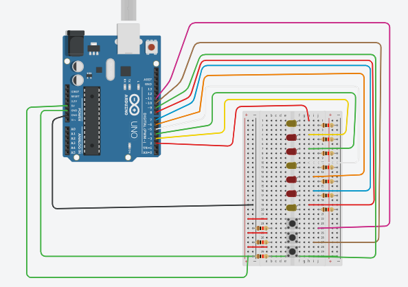
Materials Needed:
- 1 Arduino Uno
- 3 Push Buttons
- 3 Yellow LED's (colors could be different)
- 4 Red LED's (colors could be different)
- 10 1 Kilo Ohm resistors (1000 Ohm)
- 13 Long Jumper wires
- 3 short Jumper wires
1. Place the LED's as shown in the image. Use a different color LED to represent each floor, and one color to represent the elevator moving in between floors.
2. Connect a long jumper wire to the anode of each LED. Starting with the lowest LED on your board (Ground Floor), connect each Jumper wire in order starting at port 8 (ground Floor LED) and then work your way down to port 2(Third Floor LED).
3. Place a 1 kilo ohm resistor between the cathode of each LED and the negative bus on the breadboard. Run a Jumper wire from the negative bus to a ground port on the Arduino board.
4. Connect the buttons as shown in the image. Run a long jumper wire from one lead of the button to ports 11(3rd floor button), 10 (2nd floor button), and 9 (ground floor button). These will serve as your digital read wires that tells Arduino if the button is pressed or not. You will also need to connect each button up to the 5V port on your Arduino. Finally, connect a 1 kilo ohm resistor to the other leg of the button and return that lead to the ground.
Step 2: Your All Set Up, Start to Write the Sketch
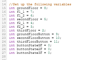
Create the following variables for the sketch. These variable should be located above the "void setup()" function. They will allow you to identify the ports that the buttons and LED's are plugged into so you do no need to remember the port number as you program.
Step 3: Set Up the "void Setup()" Function
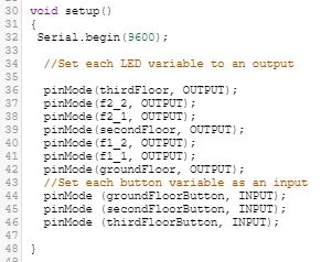
You will need to tell Arduino Uno which ports are outputs and which ports are inputs. The LEDs that identify where the elevator is at are all outputs. When a button is pressed, it is considered an input. The program identifies the input and the LEDs will be told to light up based on which input (or button) is being activated.
Use the attached image as a guide for setting the inputs and outputs.
Step 4: the Void Loop


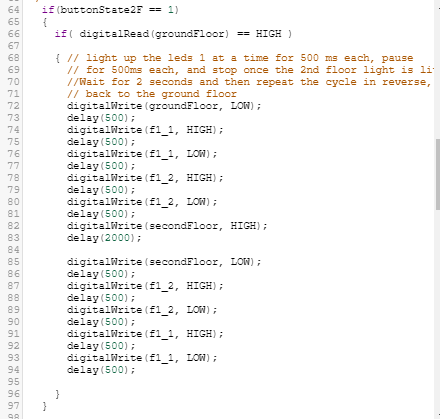
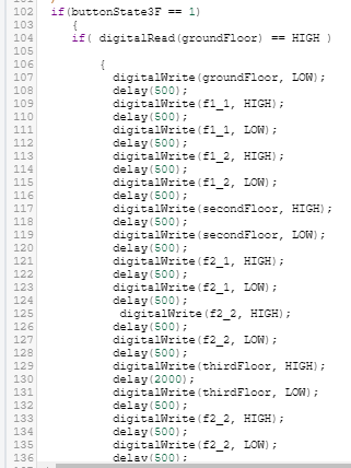
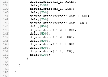
This is where you tell the Arduino what to do. You will utilize the variables that you have setup up to write commands and program flow that will make the elevator perform as described in the introduction.
- The first part of the void loop() function as shown in the first image tells the variable for the each button to equal the digitalread port. This is telling the program that if the button is pressed it should equal 1 and if it is not pressed it should equal 0. Those values will be used later to tell the elevator when to move.
- . The second image shows your first command, this will turn the ground floor LED on to show that the elevator is on the ground floor. It is important that this happens above any of the "if{condition}" statements that will follow it. More on this to come...
- The third image shows an if{condition} statement. In our language it reads "if the 2nd floor button is pressed, complete the commands inside of the curly braces { }. If the button is not pressed the program will not perform these commands. You will notice inside of that "if" statement that there is another "if" statement. The second if statement in this program looks to see if the ground floor LED is on; if it is (and it should be on because we told it to be on in line 59) it will perform the commands necessary to raise the elevator to the 2nd floor. Use the digitalwrite() and delay() commands to tell the Arduino which LED to light up and for how long. Use image three to help you with this part.
- The fourth image shows another "if" statement inside of an "if" statement. This is the same setup as the 2nd floor setup, but it is looking to see if the third floor button is pressed and the ground floor LED is on. When this both of these are true, the LEDs will turn on in the same fashion, but will go all the way up to the third floor and go back down. See the last two images for the setup of this portion.
- Test it out. See if the sketch works, if you get any errors, make sure to check your curly braces!
Step 5: Bonus Challenge
The lesson is done at this point, but you may have noticed that the sketch has three buttons, but you only used two buttons. I included the ground floor button for an additional challenge for the ambitious people out there. If this is you try this:
Modify or rewrite the sketch so that the elevator will stay on the called floor until another floor is called. The elevator should be able to go from any floor to another floor. It should not return to the ground floor unless the ground floor is called.