Electronic TattleTale / Fridge Monitor
by bdwalker1 in Circuits > Microcontrollers
3651 Views, 49 Favorites, 0 Comments
Electronic TattleTale / Fridge Monitor
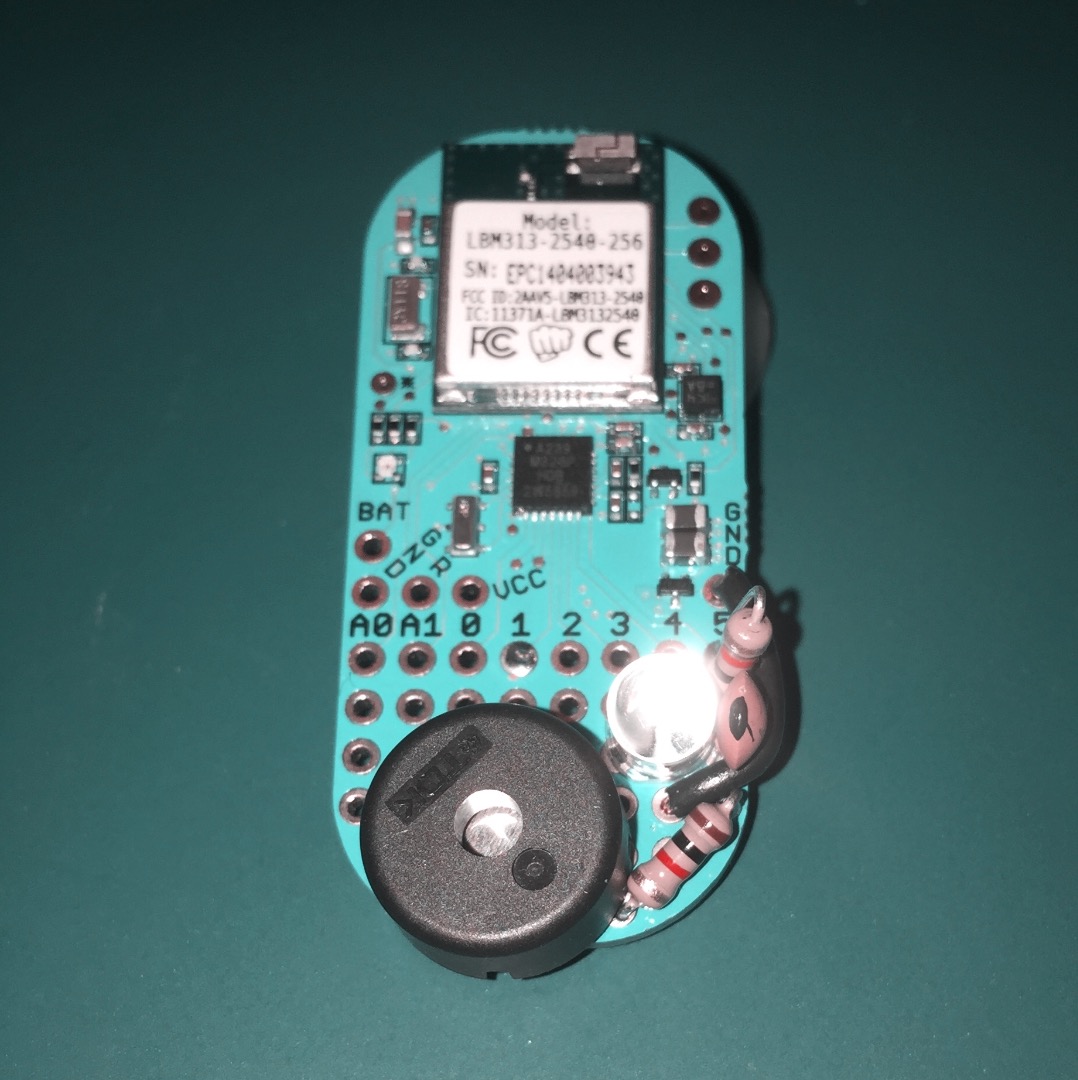
A great beginner's project for the LightBlue Bean from Punch Through Design. Once finished you will have a compact device that can detect the presence or absence of light, monitor temperature and provide audible alerts based on these environmental parameters. This project assumes you are familiar with programming the LightBlue Bean with Arduino sketches -- if you need more information on working with the LightBlue Bean and Arduino please visit http://punchthrough.com/bean/
The Components
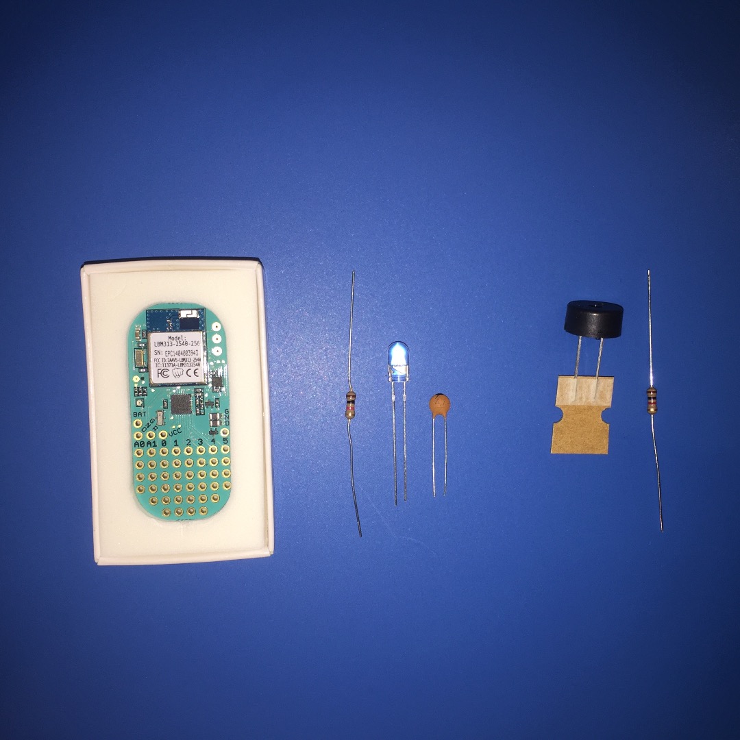
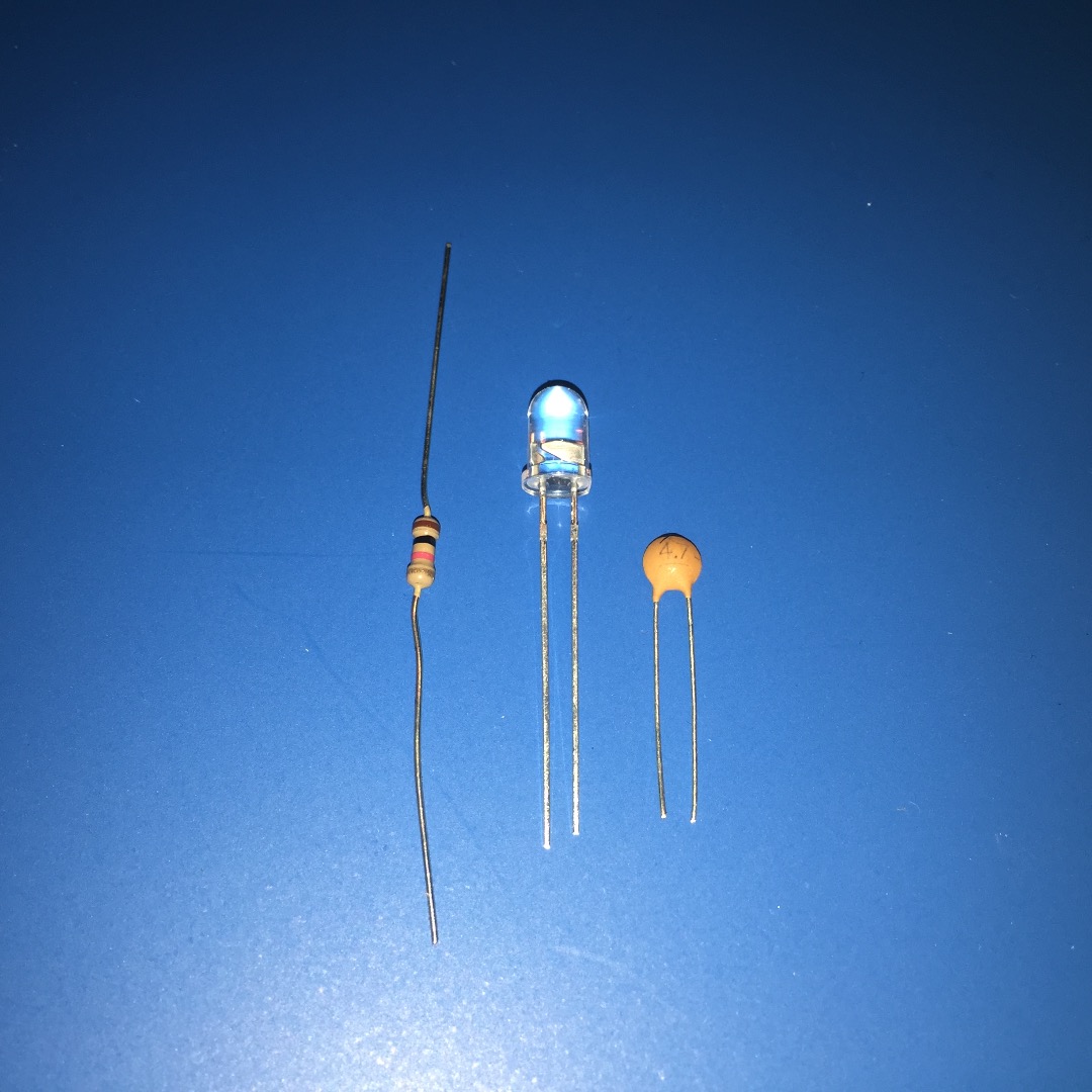
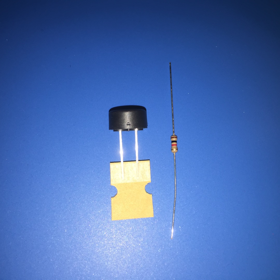
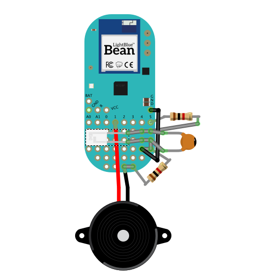
This project can be built with components from the Maker's Kit that comes with a LightBlue Bean 4-pack; if you don't have a Maker's Kit the components should also be readily available from various electronics suppliers. Components needed: one LightBlue Bean micro controller, two 1k ohm resistors, one phototransistor, one 4.7pF ceramic capacitor and one piezo speaker.
NOTE: Before proceeding with the wiring steps remember to remove the battery from the LightBlue Bean to prevent accidentally shorting something while you are working.
Wiring the Light Sensor Circuit
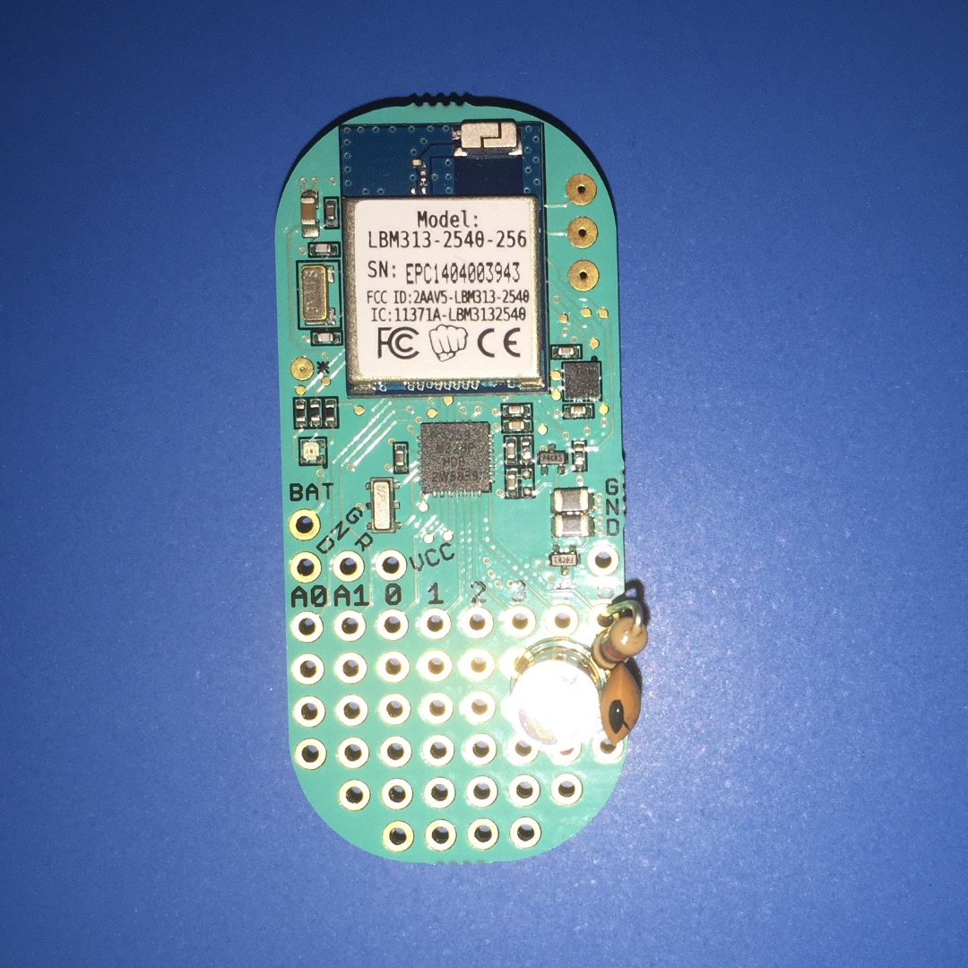
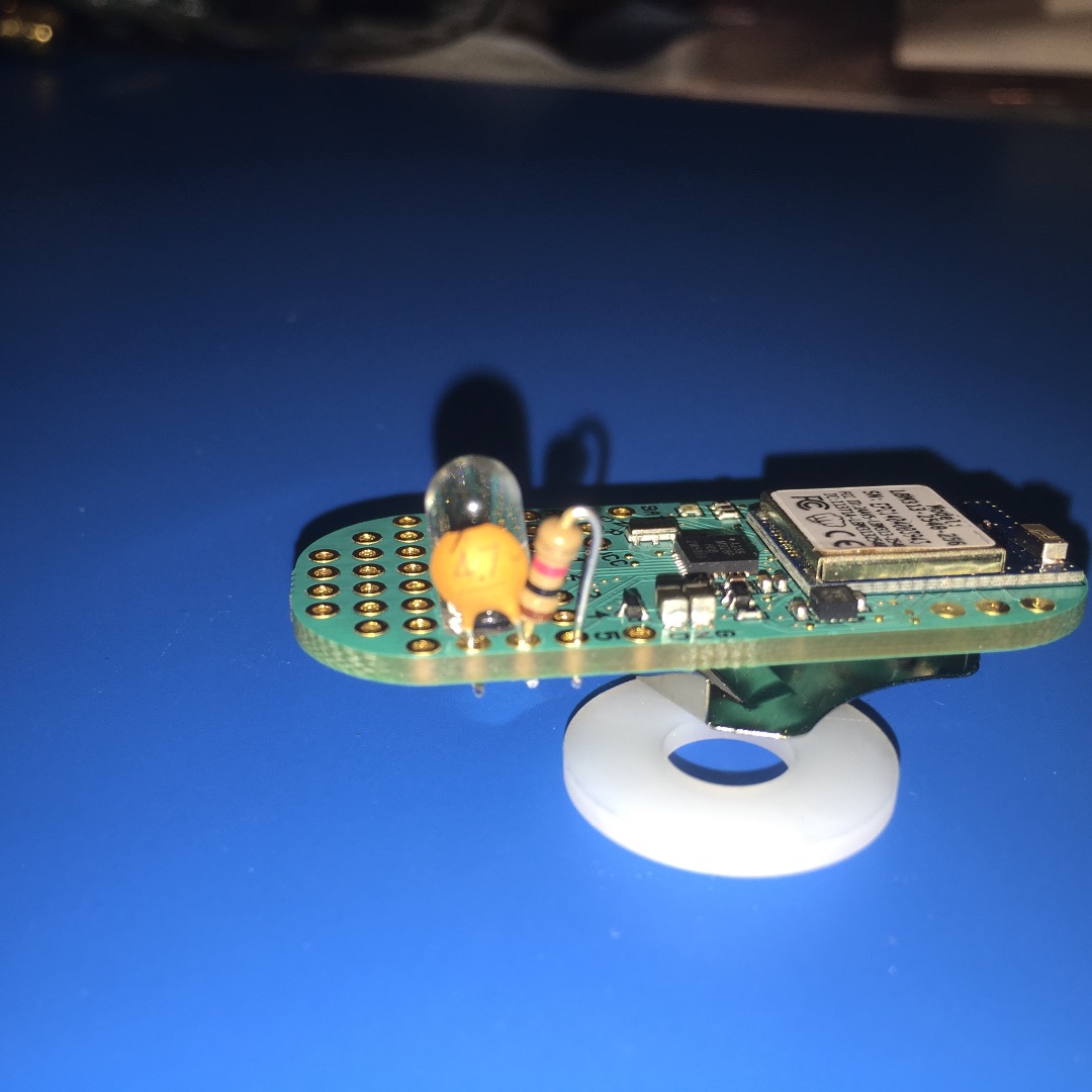
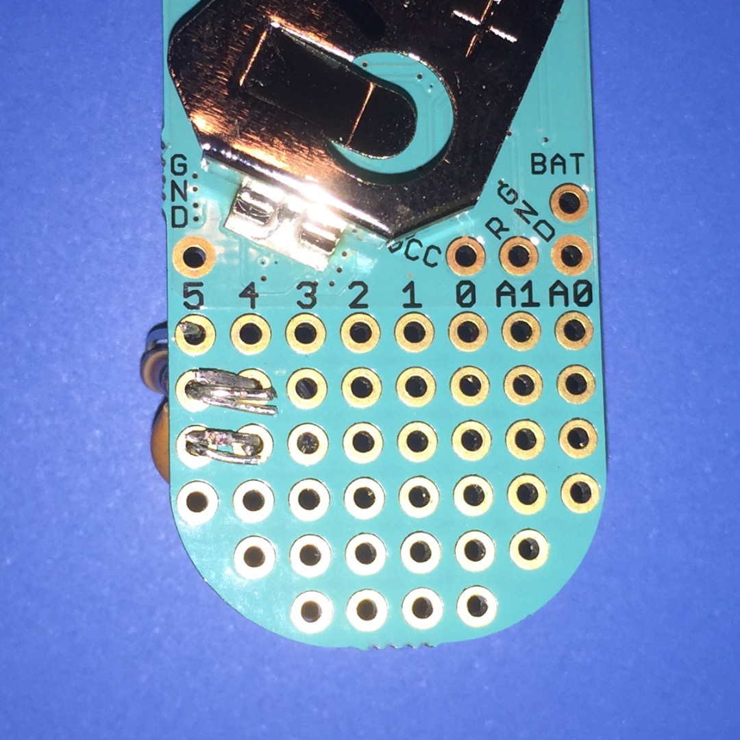
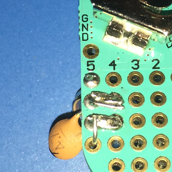
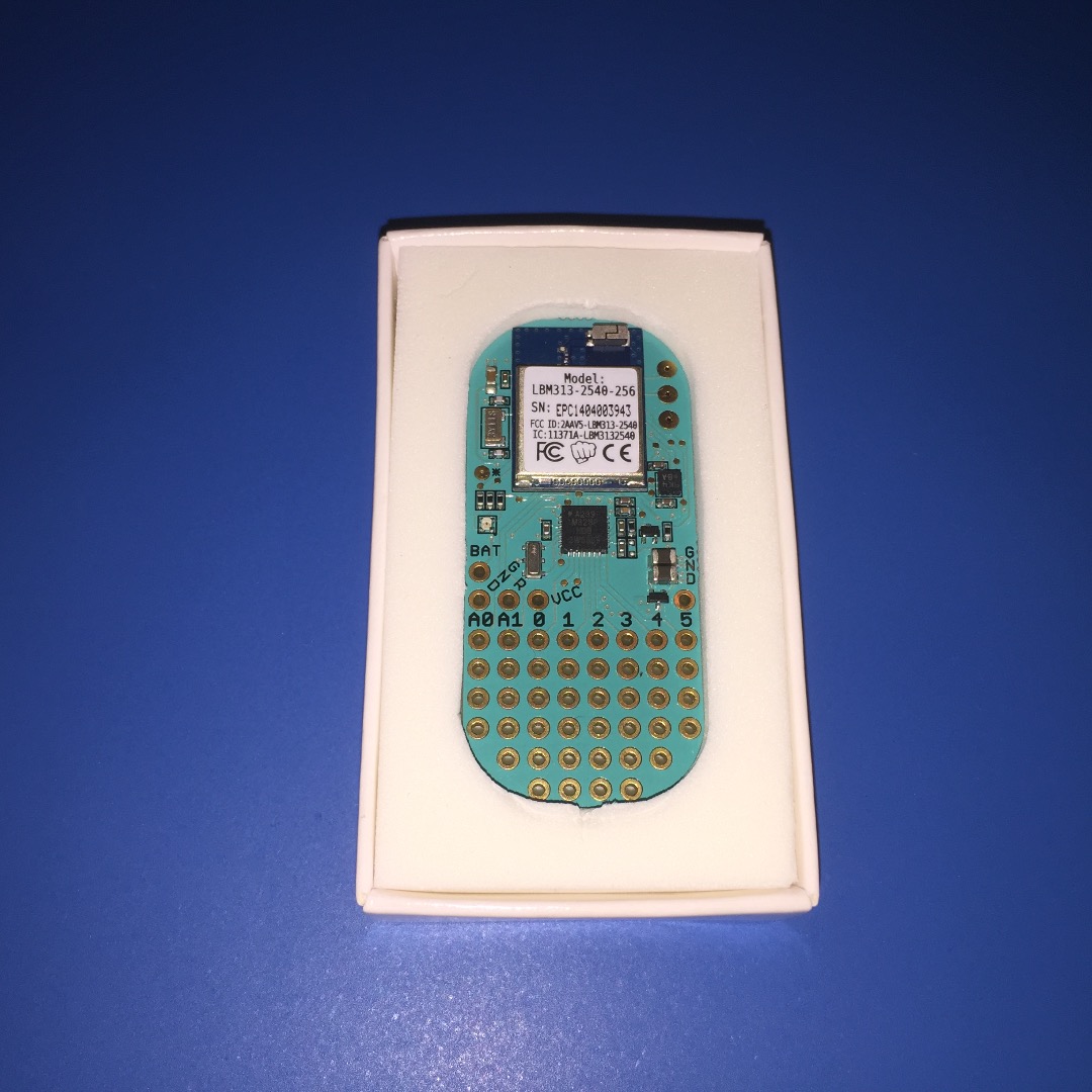
The light sensor is built using a charge-transfer circuit using a resistor, capacitor and phototransistor. The resistor is mounted in a vertical orientation between the Bean's digital pin 5 and the prototyping hole directly below pin 5. The capacitor mounts with one lead sharing the prototyping cell with the resistor and the other lead in the next prototyping hole down. The phototransistor mounts with the collector in the prototyping hole below digital pin 4 and the emitter in the next prototyping hole down. (The phototransistor's emitter should be indicated by a shorter lead and/or a slightly flattened side.)
Wiring the Buzzer
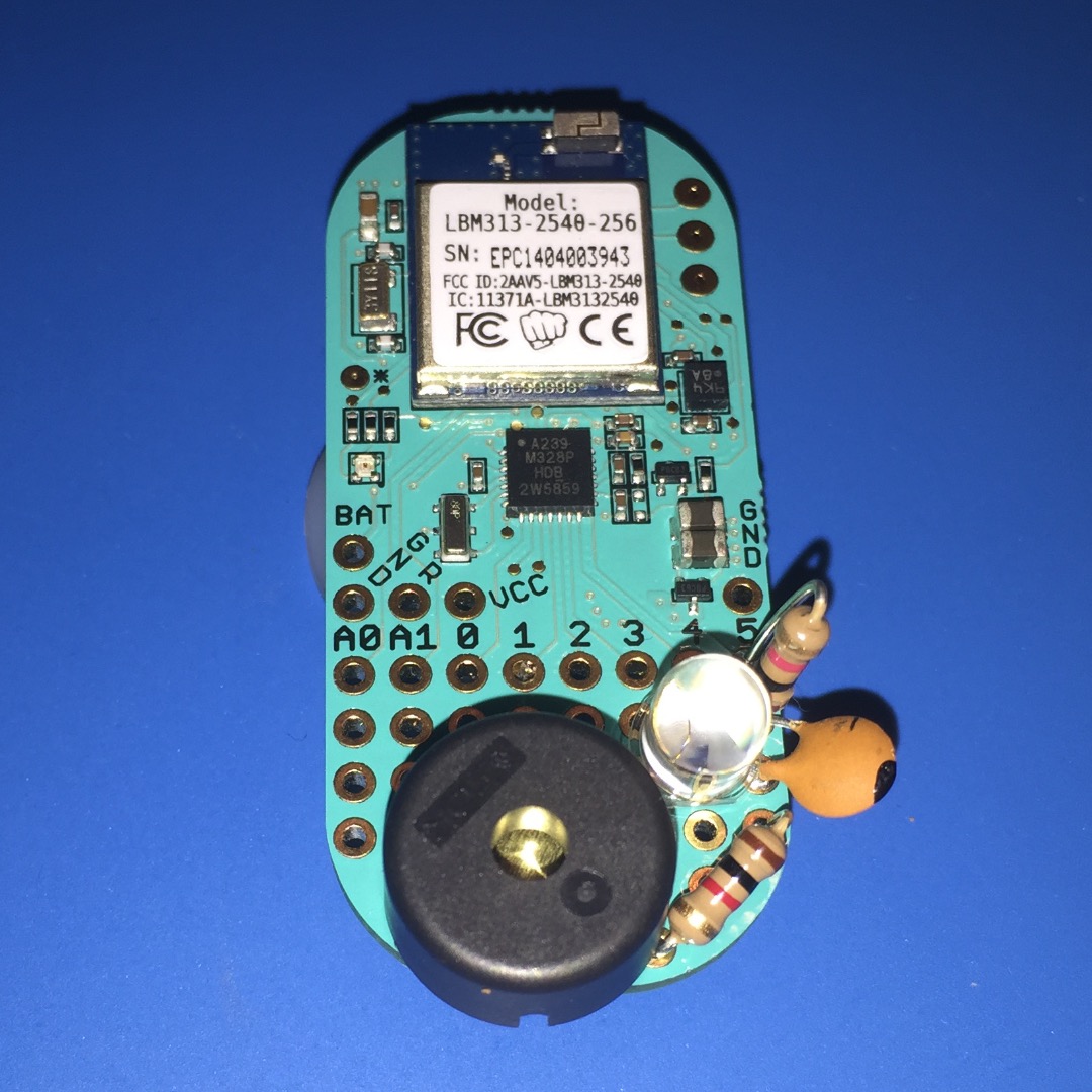
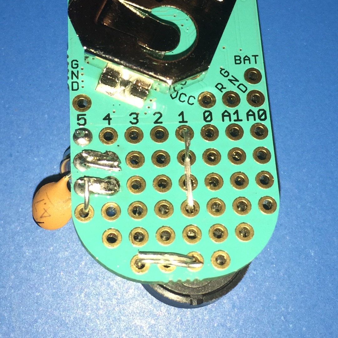
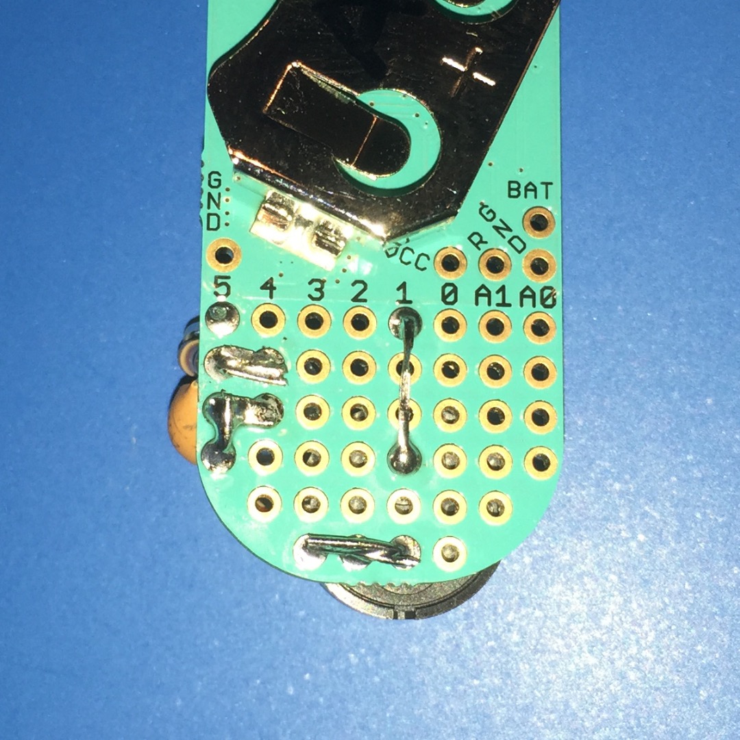
To wire the buzzer circuit, mount the 1k ohm resistor at an angle on the lower-right corner of the Bean. One lead will be in the prototyping hole directly below the capacitor, and the other lead will be in the right-most hole in the bottom row of prototyping holes. The piezo buzzer will connect to the resistor lead in the bottom row of prototyping holes, and then also connect to digital pin 1. The piezo buzzer from the Maker's Kit mounts nicely with one lead in the 2nd hole in the bottom row of the Bean's prototyping area and the other lead two rows up. If you are using a different piezo buzzer find what works best for you. If your piezo buzzer has red and black leads (or is otherwise marked with a positive and negative lead) be sure the positive lead is connected to digital pin 1 and the negative lead to the resistor.
Adding a Ground Wire
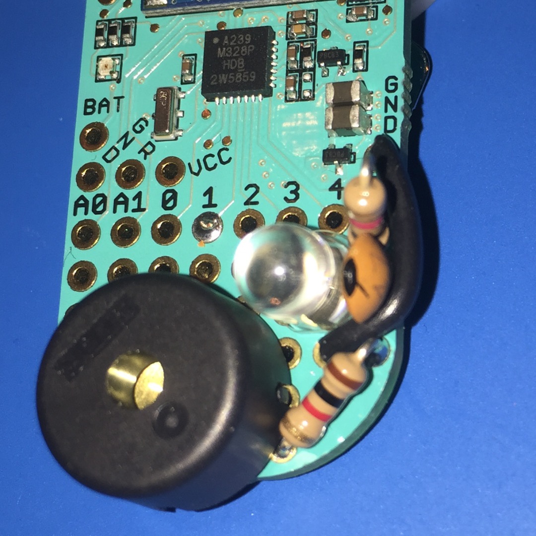
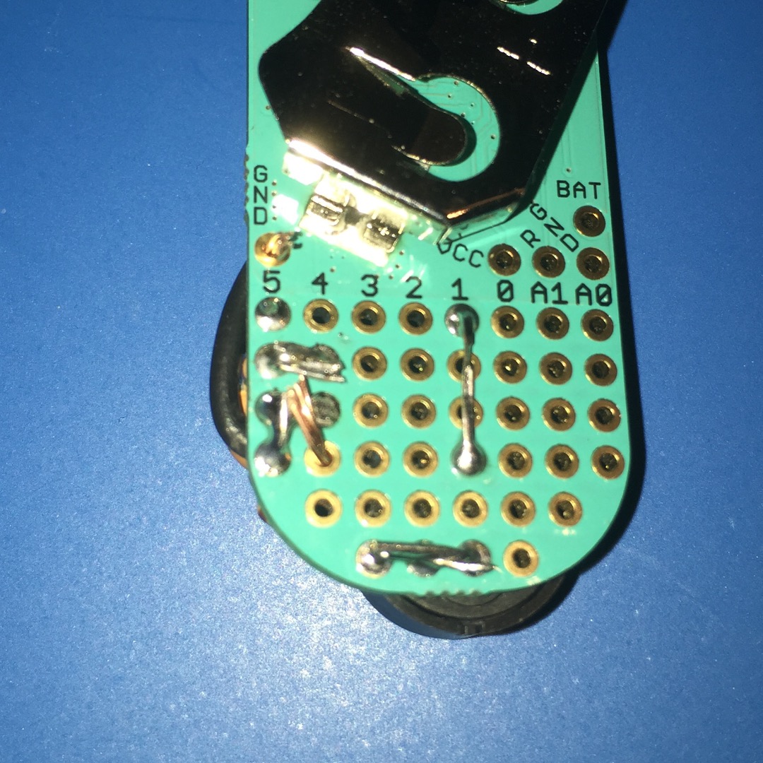
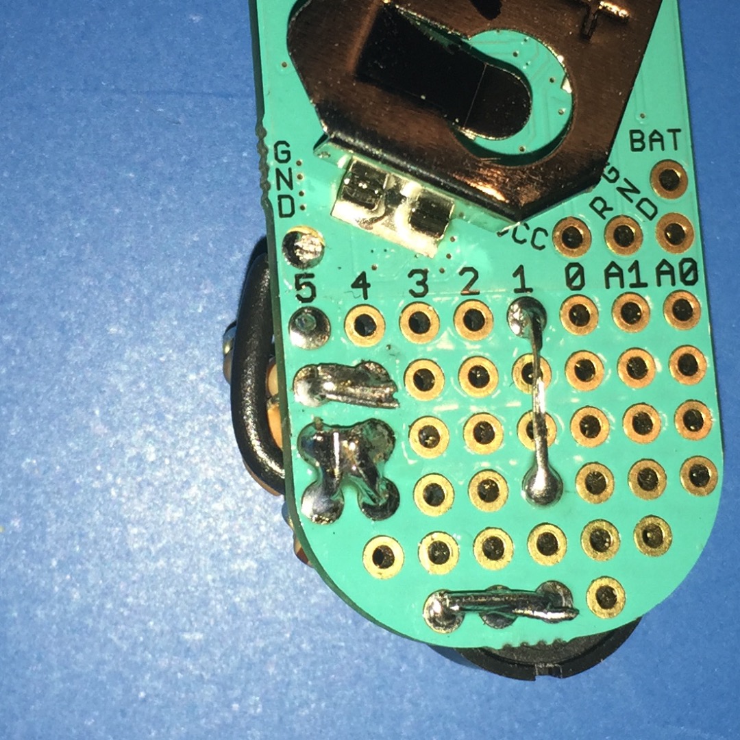
Add a ground wire from GND to the node where the light sensor and speaker circuits meet.
Starting the Arduino Sketch
We'll start the Arduino sketch by setting up a simple template and some parameters we will need later on. By defining constants for the light sensor and buzzer functions at the top of the sketch it will be easy to adjust these values later if you want to.
// Constants for light sensor<br>const int LIGHT_SENSOR_PIN = 5;
const uint32_t DARK_DISCHARGE_THRESHOLD = 300;<p>// Constants for buzzer
const int BUZZER_PIN = 1;
const int OPEN_WARNING_TONE = 500;
const int OPEN_WARNING_DURATION_MS = 1000;
const int TEMP_WARNING_TONE = 800;
const int TEMP_WARNING_DURATION_MS = 500;
const int TEMP_WARNING_REPEAT = 3;

void setup() {
  // Initialize Serial comms
  Serial.begin();

  // Init Bean LED to off
  Bean.setLed(0,0,0);

  // Set light sensor pin mode
  pinMode(LIGHT_SENSOR_PIN, INPUT_PULLUP);
}

void loop()
{
    Bean.sleep(500);
}
</p>
The Light Sensor Code
Next we need a function for handling the light sensor charge-transfer circuit. The basics of this function are to briefly set pin 5 high to charge the circuit, then time how long it takes the pin until to go low. The more light hitting the phototransistor the faster the circuit will discharge. The qtTime() function handles this charging and timing. The lightCheck() function uses the qtTime() function to indicate whether the Bean is in the light or dark. Then we will use lightCheck() within loop() to test our light sensor circuit.
uint32_t qtTime(int nQTPin, uint32_t nMaxWait)
{
    // Charge the capacitor
    digitalWrite(nQTPin, HIGH);
    delay(5);
    // Stop charging
    digitalWrite(nQTPin, LOW);
    // Start discharge cycle
    uint32_t nStart = millis();
    uint32_t nDuration = 0;
    // As capacitor discharges through phototransistor sensor
    // pin will transition from HIGH to LOW
    while(digitalRead(nQTPin) == HIGH)
    {
        // Wait for discharge
        // In case millis() has rolled over
        if ( millis() < nStart )
        {
            nStart = millis();
        }
        // Has duration exceeded the DARK threshold time?
        nDuration = millis() - nStart;
        if ( nDuration > nMaxWait )
        {
            break;
        }
    }

    // For determining threshold or degugging, output duration
    String strDuration = "";
    strDuration += String(nDuration);
    strDuration += " ms";
    Serial.println( strDuration );
    // Above section can be removed or commented once lightCheck()
    // is working as desired.

    return nDuration;
}
String lightCheck() {
String strOut = "LIGHT";
if ( qtTime( LIGHT_SENSOR_PIN, DARK_DISCHARGE_THRESHOLD) >= DARK_DISCHARGE_THRESHOLD )
{
strOut = "DARK";
}
// Return LIGHT or DARK
return strOut;
} void loop()
{
Serial.println( lightCheck() );
Bean.sleep(500);
}Testing the Light Sensor

Now is a good time to test the light sensor circuit. Insert a coin cell battery into your Bean then compile and upload the sketch to your Bean. After upload, use Bean Loader to activate Virtual Serial for your Bean and then open the Serial Monitor in the Arduino IDE. If you completely cover and uncover your Bean you should see output like the image above. You can adjust the value of the DARK_DISCHARGE_THRESHOLD constant so that the sketch reports dark only when the Bean is completely in the dark. I adjusted mine such that even if the fridge door is closed enough to turn the light off, but the door isn't sealed it still reports LIGHT; but when the door is sealed tight it reports DARK.
Making Noise
Once you have the light/dark sensor working how you want it you can create two functions for making the buzzer work. The playTone() function handles the sound output. The warningTone() function calls the playTone() function to output the specific sounds for our circuit. Then to test the sound functions we can modify the loop() function to output different tones for LIGHT and DARK conditions.
void playTone(uint8_t nPin, uint16_t nFreq, uint16_t nDuration)
{
    // If frequency or duration is zero, stop any tones
    if ( (nFreq == 0) || (nDuration == 0) )
    {
        noTone(nPin);
    }
    else
    {
        // Output the specified tone for the specified duration
        tone(nPin, nFreq, nDuration);
        // Since we need the tone to occur synchronously we wait for it to finish
        delay(nDuration);
    }
}
void warningTone( uint16_t nFreq, uint16_t nDuration, uint8_t nCount)
{
// Setup a loop counter
int n = 0;
// While the loop counter is less than the specified count ...
while (n++ < nCount)
{
// ... play the specified tone.
playTone(BUZZER_PIN, nFreq, nDuration);
// if we will repeat, pause briefly so the tones don't run together.
if (n < nCount)
{
delay(250);
}
}
} void loop()
{
if (lightCheck() == "LIGHT")
{
warningTone( OPEN_WARNING_TONE, OPEN_WARNING_DURATION_MS, 1 );
}
else
{
warningTone( TEMP_WARNING_TONE, TEMP_WARNING_DURATION_MS, TEMP_WARNING_REPEAT );
}
Bean.sleep(500);
}Tracking Time
Now we need to start tracking how long the Bean is in the LIGHT state. Because the timers on the Bean's Arduino circuit are turned off during Bean.sleep() we need to set up some variables and functions for time tracking. Above the setup() function create these variables:
// Global variables for time tracking
uint32_t nLoopStart = 0;
uint32_t nApproxRunTime = 0;
Then, create two helper functions for time keeping:
uint32_t approxRunTime()
{
  return (nApproxRunTime + (millis() - nLoopStart));
}

void updateApproxRunTimeForSleep( uint32_t nSleepTime )
{
  nApproxRunTime += (millis() - nLoopStart) + nSleepTime;
  nLoopStart = millis(); // Reset nLoopStart since we have added                                              // loop time to nApproxRunTime
}
To keep track of time we need to set nLoopStart at the top of loop(). We also need to adjust nApproxRunTime for the sleep time at the bottom of loop().
void loop() {
    // For time tracking we need to know when the loop() started
    nLoopStart = millis();

    // Check the light condition, if LIGHT ...
    if (lightCheck() == "LIGHT")
    {
        warningTone( OPEN_WARNING_TONE, OPEN_WARNING_DURATION_MS, 1 );
    }

    // Output approxRunTime() for testing
    Serial.print( approxRunTime() );
    Serial.println( "ms" );

    // Determine our loop sleep time based on conditions
    int nSleepTime = 15000; // 15 seconds standard sleep time
    // Before sleep, update approximate run time
    updateApproxRunTimeForSleep( nSleepTime );
    // Sleep
    Bean.sleep(nSleepTime);
}
When you compile/upload these changes the Serial Monitor output should look something like below -- you'll notice our discharge time alternating with our approximate total run time. (Since we are done setting up the light sensor circuit I will comment out the discharge time output.) Note: Be aware that this time keeping will not be super precise; we are approximating the total run time based on loop execution time and how long we tell the Bean to sleep, but we are not accounting for time it takes the Bean to put the arduino to sleep or time it takes to wake-up the arduino. We're also not accounting for the possibility of the arduino being woken up early by Serial input to the Bean.
2 ms
1067ms
0 ms
17218ms
2 ms
33367ms
202 ms
49723ms
Tracking Fridge Open Time
Now that we have a way of keeping track of time, we need to keep track of when the fridge door is open (aka when we sense LIGHT). First, we should add some constants near the top of our sketch for our warning parameters:
// Constants for warning thresholds and repeat intervals
const uint32_t OPEN_WARNING_TIME_SEC = 60;
const uint32_t OPEN_WARNING_INTERVAL_SEC = 15;
We also need to add some global variables for tracking light state. Add these above setup():
// Global variables for warning tracking
boolean bLightOn = false;
uint32_t nLightOnStart = 0;
uint32_t nLastLightOnWarning = 0;
And we can update our loop() by replacing
// Check the light condition, if LIGHT ...
if (lightCheck() == "LIGHT")
{
    warningTone( OPEN_WARNING_TONE, OPEN_WARNING_DURATION_MS, 1 );
}
// Output approxRunTime() for testing
Serial.print( approxRunTime() );
Serial.println( "ms" );
with
// Check the light condition, if LIGHT ...
if (lightCheck() == "LIGHT")
{
    // ... if it was not light last time through loop ...
    if (!bLightOn)
    {
        // ... set light on flag and reset light on duration.
        bLightOn = true;
        nLightOnStart = approxRunTime();
    }
    else
    {
        // If it was light before and the light has been on longer than our warning threshold ...
        if ( (approxRunTime() - nLightOnStart) >= (OPEN_WARNING_TIME_SEC * 1000) )
        {
            // ... and if our last light on warning was longer ago than our interval ...
            if ( (approxRunTime() - nLastLightOnWarning) >= (OPEN_WARNING_INTERVAL_SEC * 1000) )
            {
               // ... then reset our last warning time ...
                 nLastLightOnWarning = approxRunTime();
        // ... and play warning tone.
                warningTone( OPEN_WARNING_TONE, OPEN_WARNING_DURATION_MS, 1 );
            }
        }
    }
}
else
{
    // If not LIGHT, ensure light on flag is false.
    bLightOn = false;
}
And we can adjust our loop's sleep time based on whether the light is on or not. This will save battery by sleeping longer during periods of darkness. So, after
int nSleepTime = 15000; // 15 seconds standard sleep time
we add
f (bLightOn)
{
    nSleepTime = min(nSleepTime,(OPEN_WARNING_INTERVAL_SEC * 1000));
}
Now if we have detected light for 60+ seconds we should hear a warning beep about every 15 seconds.
In case you have any trouble with the code changes, I have attached the current sketch.
Downloads
Monitoring Temperature
What we have built so far could be used to monitor access to anyplace that is usually dark; you could create an alarm for your closet, drawer, toolbox, lunchbox, etc. Since we are building a refrigerator monitor and the Bean has an on-board temperature sensor we can upgrade our tattletale to also monitor the refrigerator's internal temperature. We need to add a few constants for temperature monitoring:
const int8_t TEMP_WARNING_LOW_CELSIUS = 1;
const int8_t TEMP_WARNING_HIGH_CELSIUS = 5;
const uint32_t TEMP_WARNING_INTERVAL_SEC = 5;
And we also need a couple of global variables for tracking temperature events:
boolean bTempProblem = false;
uint32_t nLastTempWarning = 0;
Now create two functions for performing the temperature checks. The temperatureOkay() function checks if the current temperature is within the acceptable range. The checkTemperature() function uses the temperatureOkay() function and gives warning tones as appropriate.
boolean temperatureOkay()
{
    boolean bTempOkay = true; // Default return value to true
    // Get the current temperature in degrees Celsius
    int8_t nTemp = Bean.getTemperature();
    // If the current temperature is not in the acceptable range ...
    if ( (nTemp < TEMP_WARNING_LOW_CELSIUS) || (nTemp > TEMP_WARNING_HIGH_CELSIUS) )
    {
        // ... set return value to false.
        bTempOkay = false;
    }
    return bTempOkay;
}
void checkTemperature()
{
// If the temperature is out-of-range ...
if (!temperatureOkay())
{
bTempProblem = true;
// ... and if our last warning was more than our interval ago ...
if ( (approxRunTime() - nLastTempWarning) > (TEMP_WARNING_INTERVAL_SEC * 1000) )
{
// ... reset our last warning time ...
nLastTempWarning = approxRunTime();
// ... and give warning tones.
warningTone( TEMP_WARNING_TONE, TEMP_WARNING_DURATION_MS, TEMP_WARNING_REPEAT);
}
}
else
{
bTempProblem = false;
}
} Now we can add the temperature check to loop() after the LIGHT checks and before we prepare to sleep.
// Temperature check
checkTemperature();
We should also adjust our sleep time when we are in a temperature warning condition so warnings will be close to the desired interval.
if (bTempProblem)
{
    nSleepTime = min(nSleepTime,(TEMP_WARNING_INTERVAL_SEC * 1000));
}
Our sketch should now be complete. You may need to adjust the various warning thresholds to suit your particular fridge, Bean, etc.
Downloads
At Home in the Refrigerator
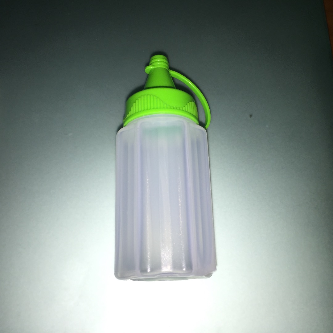
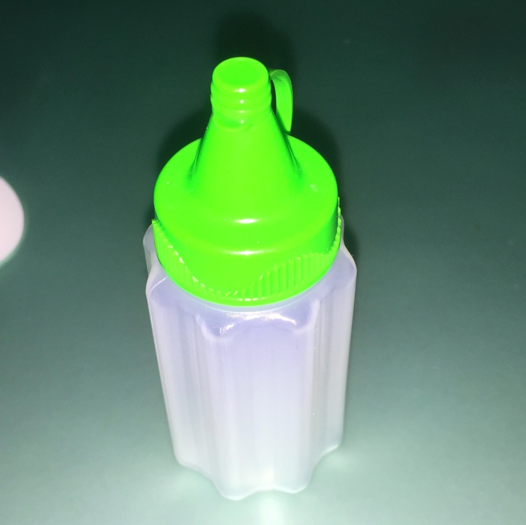
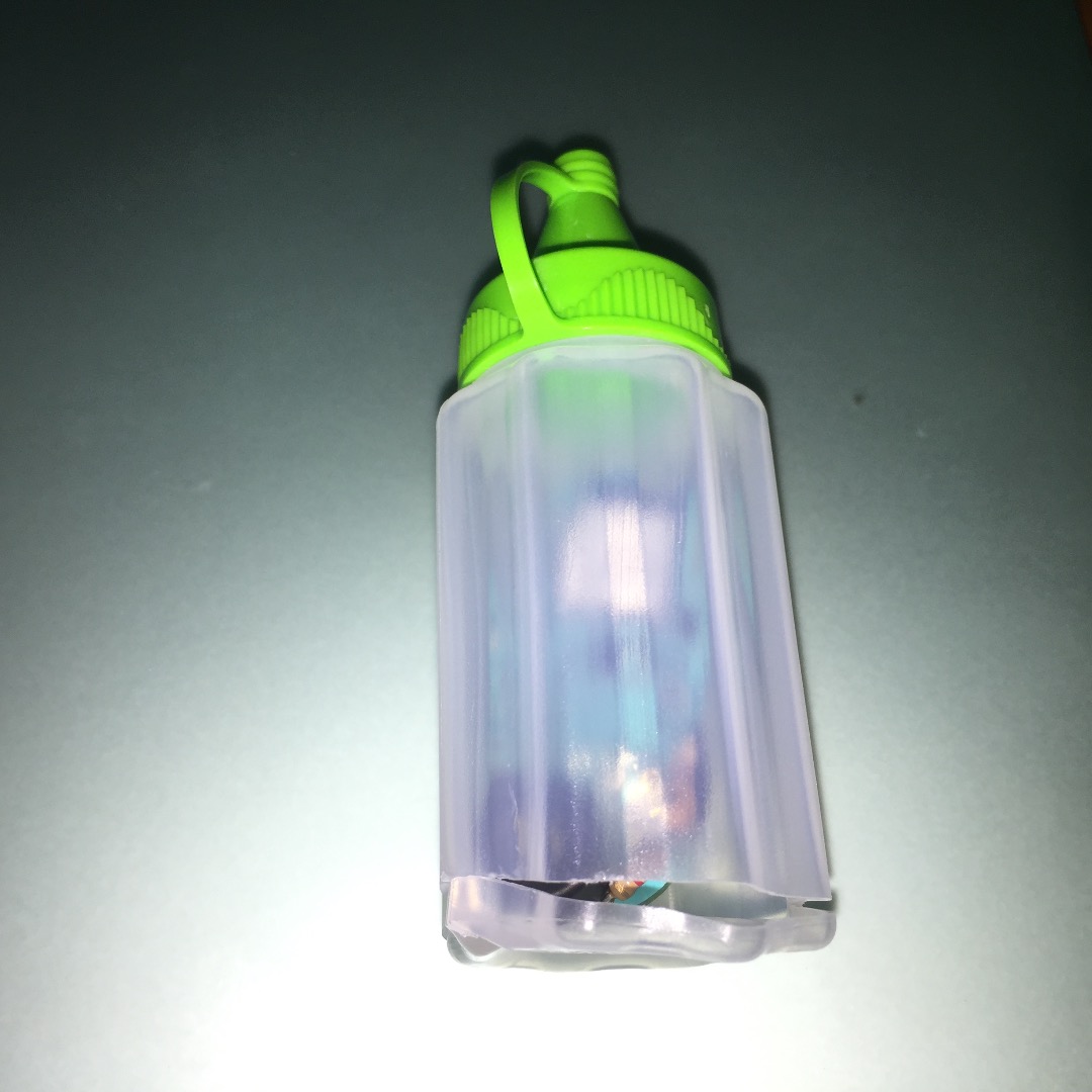
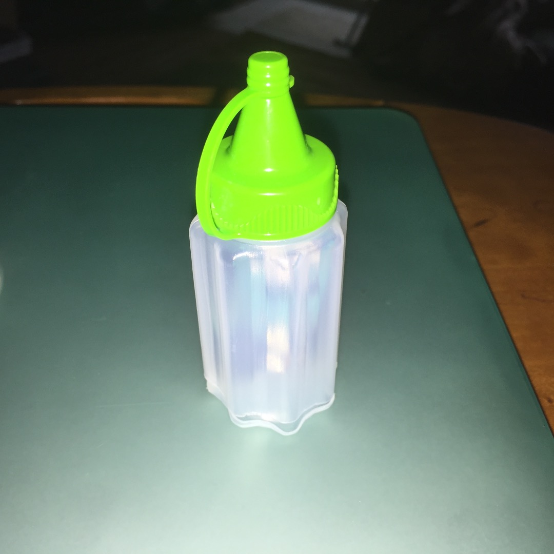
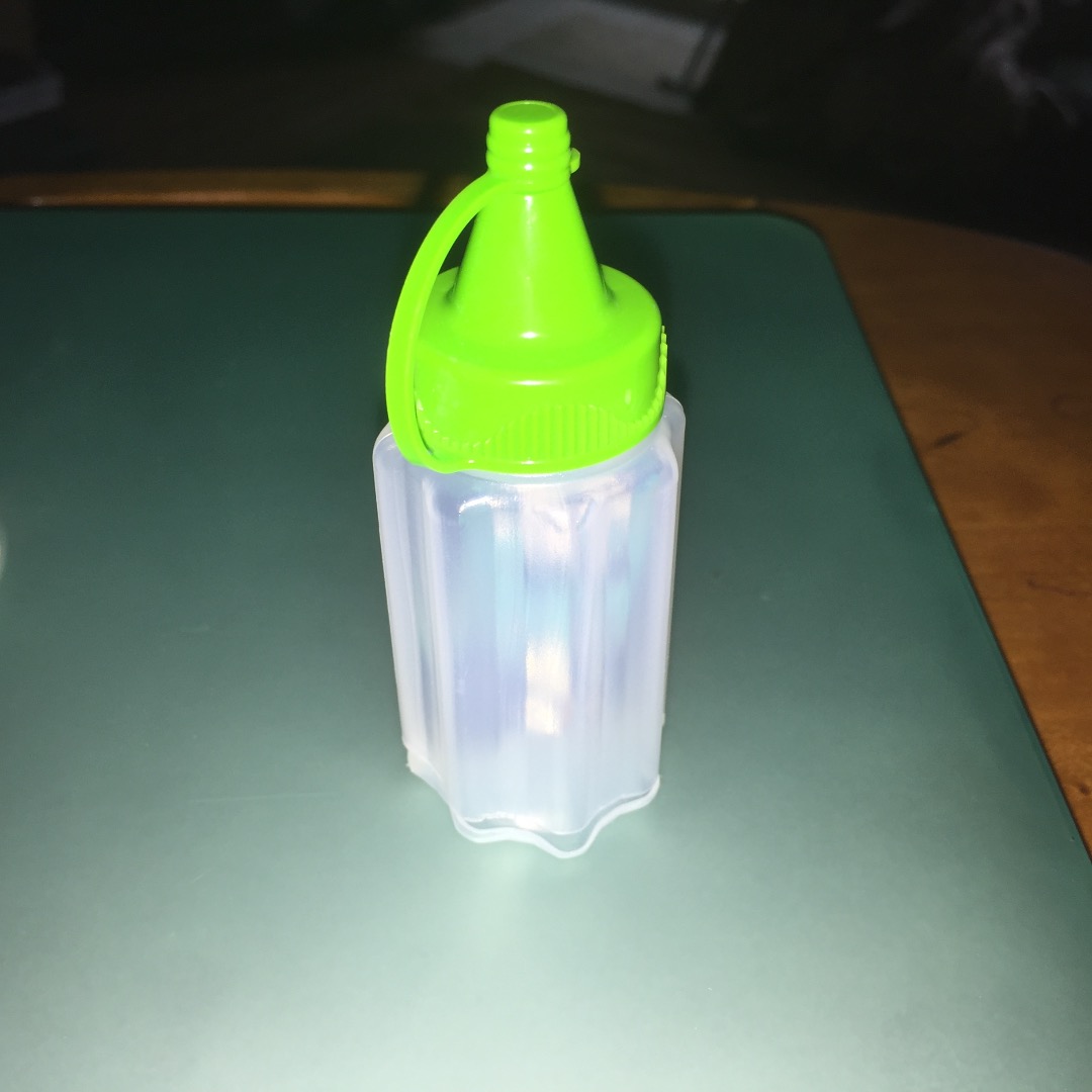
To keep my tattletale from looking too out-of-place in the fridge I bought a small condiment bottle at Target. I cut a small window in one side for sound then cut the bottom open to insert my Bean.
I hope you have had fun with this project. I don't know how long this project will run on a single CR2032 coin cell battery. Maybe I will get a chance later to analyze and optimize battery life.
Post Build Notes
After building my TattleTale I tested it in my fridge. Initial testing was promising, but after several hours I tested again and got no warning buzzer. I pulled out my iPhone to try to connect to the Bean, and it was not showing as active. I found it highly unlikely that the battery could have died in such a short period of time, but that's what appeared to have happened. I removed the TattleTale from the fridge to replace the battery later.
After 10-15 minutes I noticed that the LED on my Bean flashed a few times then remained off. I then tried to connect to the Bean from my phone and was able to. The TattleTale had come to life, but battery level reported was a tad low. Another 5 minutes passed, and I checked again. The battery was back up to over 2.5 volts. Evidently the CR2032 battery I have does not operate well at near freezing temperatures (despite the fact all data sheets I can find say that the operating temperature for a CR2032 should go well below freezing).
I hooked a 2xAA battery holder up to my TattleTale and placed it back into the fridge. More than 24 hours later it is still working as intended.