Easy Joule Thief Soldering Project
by MakersBox in Circuits > Electronics
6884 Views, 31 Favorites, 0 Comments
Easy Joule Thief Soldering Project


The Joule Thief is a clever little circuit that can light a LED with a battery that is nearly dead. It does this with a pair of opposing magnetic fields. I like this circuit because it is simple to build, yet demonstrates some very complex electrical behavior.
I've designed a printed circuit board to help make this easier to build for beginning Makers. I used open source KiCAD software to lay it out (a future Instructable?), and OSHPark to manufacture it. If you want to just wire one up without the board, check out Angelo's Instructable which uses essentially the same circuit.
If you want to learn a bit more about the principles that make this circuit work, check out this video: http://youtu.be/0GVLnyTdqkg
A kit for this project is available on Tindie.com. Purchasing the kit will save you the time and expense of ordering from several different vendors and avoid the minimum PCB order premium. You will also be helping me develop and share other projects!
Gather the Parts and Tools

I've seen a number of different circuits using an array of parts, so it is certainly possible to do this with what you have on hand. Here is what I'm using:
- 1 - PCB, https://oshpark.com/shared_projects/rLeF8F88 ($4.85 for 3 copies, free shipping)
- 2 - AA Battery Clip, Keystone Electronics #92
- 1 - Ferrite Tubular Bead, Digi-Key 240-2301-ND or similar
- 1 - SPDT slide switch, E-Switch EG1218
- 1 - 1K resistor 1/8 - 1/4 W
- 1 - 2N2222 NPN transistor or similar, Fairchild Semiconductor PN2222ATA
- 2 nanoseconds (about 24") of insulated wire. Two different colors are helpful.
- 1 - LED, 5 or 10mm, choice of color
Remember, I've done all the hard work if you just want to buy the kit at Tindie.com.
For tools, you will need:
- Soldering iron
- solder
- wire nippers
- wire stripper
- 1 used AA battery (at 0.5V or higher)
Wind the Coil


The coil is perhaps the trickiest part to make, so lets get it out of the way first. We are looking to get between 7 and 10 wraps around the coil. This will obviously depend on the wire size and coil size.
- Start with the two strands of wire about halfway through the coil.
- Wind the pair around one side till about one inch remains .
- Repeat with the other half.
- Pull the wire tight, removing any slack.
- Strip the leads as close to the coil as possible.
- If stranded wire, twist the leads and tin with solder.
- Thread the leads through the PCB. Note: The same color wires need to go though on the same edge of the PCB, as shown by the silk screen markings. Observe in the picture how the two blue wire ends are visible on the one edge.
- Twist all the leads together at once to pull the coil tight to the board.
- Solder the leads and clip the twisted part away.
The coil should be fairly snug against the board. For additional mechanical strength, you can hot glue the coil to the board.
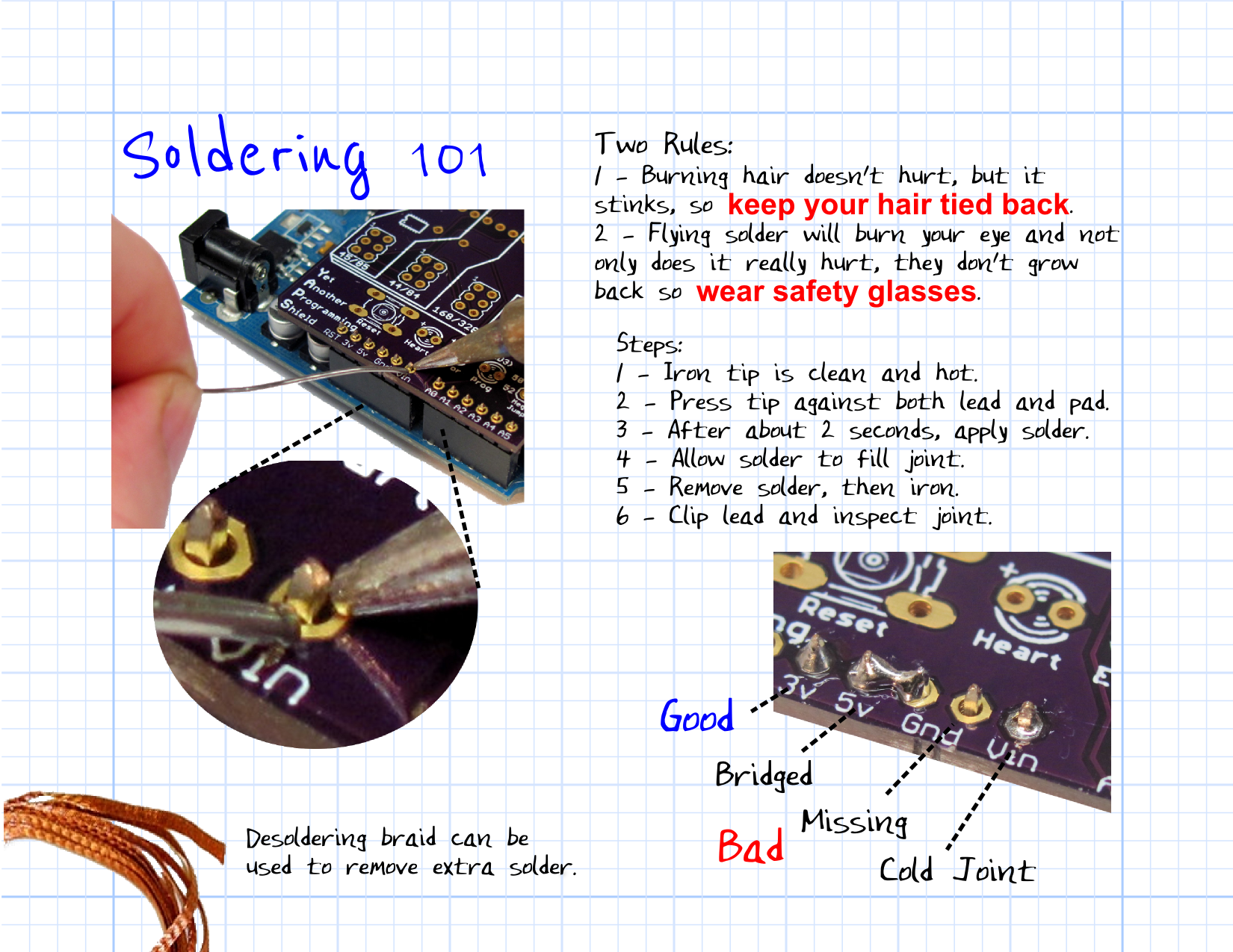
If you have never soldered before, check out SparkFun's tutorial at www.sparkfun.com/tutorials/213 and watch youtu.be/QKbJxytERvg or youtu.be/P5L4Gl6Q4Xo.
Resistor, Switch, and Transistor


Believe or not, the hard part is done! The remaining parts are standard through hole components. The order is fairly arbitrary, but I like to go lowest to highest based on height. We already blew that scheme with the coil, but lets pick up from there:
- 1K ohm resistor (no polarity).
- Slide switch (no polarity).
- NPN transistor (see note below).
Note: The transistor leads must go in the correct holes. For the Fairchild 2N2222 I'm using, this is with the flat face facing outward. Depending on transistor type and manufacturer, this may not be the case. I have marked the emitter, base, and collector leads on the silk screen so you can check it against your data sheet.
Let There Be Light


LED:
The LED can be either a 5mm or 10mm variety. An amazing feature of this circuit is that it can power a white or blue LED with a forward voltage of 3V with a battery holding only 0.5V! Any color will work, but white or blue make cool night lights!
The long lead of an LED goes through the hole marked "+". Most LEDs have a flat side as well, which denotes the negative side. I like having a 3V coin cell handy because I can never remember this.
Battery Holders:
These go on the under side of the board. They are interchangeable, but must be mounted with the openings facing each other so you can get the battery in.
Once you have the battery holders soldered in, it is time to add a battery, slide the switch toward the LED, and bask in the glorious warm LED light from your new creation!
Troubleshooting


If it doesn't light, don't loose heart! Here are some things to check:
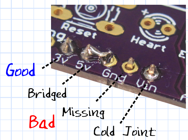
- Look at your solder joints. Any missing or bridged connections should be fixed.
- Try a fresh battery. This circuit become unstable at a low voltage and may not start if the battery is completely dead.
- Is the LED in the correct position? I like to use a 3V coin cell to bridge the two leads on the under side of the board. This will tell you if the LED is in the correct position. If it is not, unsolder it and put it in correctly. Here is a good video on how to do it: http://youtu.be/Z38WsZFmq8E
- Double check the coil leads are on the correct side.
- The solder joints should be trimmed off so they don't touch the battery casing, which might cause a short circuit. A piece of electrical tape may be needed for insulation.
- Check orientation of the transistor against the data sheet.
If all else fails, ask for help. I've tried to make this as easy and fool-proof as possible, but if you are a true beginner, you may need the help of someone more experienced. We create Instructables because we like to share the joy of our hobbies. If you are not successful in building this, you can help me by letting me help you figure out why! We are all learning in one way or another. I'm trying to learn how to make my Instructables better!