Easiest and Cheapest Way to Convert an Old DOL Motor Pump Starter to a Smart WiFi-Controlled Gadget Using NodeMCU and a 2-Channel Relay Module
by costomato in Circuits > Arduino
573 Views, 3 Favorites, 0 Comments
Easiest and Cheapest Way to Convert an Old DOL Motor Pump Starter to a Smart WiFi-Controlled Gadget Using NodeMCU and a 2-Channel Relay Module
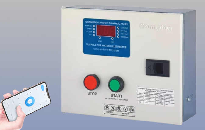
Ever found yourself lugging up and down stairs just to start or stop your motor pump? Welcome to my world! If you have a submersible motor pump at home (possibly upto 10 Hp), chances are you’re using a DOL (Direct On-Line) starter – the trusty old workhorse of motor control. But what if I told you there's a way to transform this antiquated setup into a smart device you can control from your smartphone?
Picture this: your motor is on the ground floor, and you’re lounging on the first floor, but you want to turn it on or off without playing hopscotch between floors. Sounds like a dream, right? Well, this tutorial is here to make that dream a reality!
In this guide, I’ll walk you through the process of converting your DOL starter into a Wi-Fi-controlled gadget using a NodeMCU and a 5V 2-channel relay module. No, you don’t need to be an electrical wizard or a tech guru – if you can handle a soldering iron (you might not even need to do that lol) and follow a recipe, you can definitely handle this.
I'll do my best to keep things simple, straightforward, and, most importantly, fun. Remember, I’m not an electrical engineer – I’m a computer science student who decided to play around with some hardware. So, if you see any mistakes or have suggestions, feel free to let me know.
Ready to ditch the stairs and embrace the power of remote control? Let’s dive in!
Supplies
- NodeMCU ESP8266:
- In this tutorial, we’re rolling with the NodeMCU v3. This nifty little board comes with built-in WiFi, which is crucial because we need our device to talk to the internet. You can use any microcontroller with WiFi capabilities, but if you don’t have WiFi onboard, make sure you have an external WiFi module.
- 2-Channel Relay Module 5V:
- Relays are like the bouncers of the electronic world – they let the right signals in and keep the wrong ones out. We’ll be using two relays from this module: one for the green “Start” button and one for the red “Stop” button on your motor starter. If your relay module has more channels, no worries – just pick any two and get going!
- WiFi Connection:
- Your trusty WiFi connection will be the bridge between your NodeMCU and your smartphone. Yes, even your mobile hotspot will work like a charm.
- Adafruit IO Account:
- Sign up for an account at io.adafruit.com. The free tier is more than enough for our project, so you don’t have to splurge.
- Wires:
- The unsung heroes of electronics! You’ll need some jumper wires for the NodeMCU and other wires for connecting to the AC. Think of these as the lifelines that keep everything connected and functional.
Setting Up Adafruit IO
i. Create Your Feed:
- Excited, huh? Let’s dive into Adafruit IO. First, head over to io.adafruit.com. If you haven't logged in yet, do so now. Once logged in, navigate to Feeds and click on New Feed.
- Why Create a Feed? Think of a feed as a channel through which data travels. In our case, this feed will be the communication link between your NodeMCU and the Adafruit IO dashboard. By creating a feed, you're setting up a space where data (like the state of your motor) will be sent and received.
- Feed Details: Give your feed a name, such as motor-control. You can also add an optional description if you like. This name will be used later when setting up the dashboard controls.
ii. Create Your Dashboard:
- Now, go to Dashboards and click on New Dashboard. Give your dashboard a simple name like Motor Controller Dashboard.
- Why a Dashboard? Your dashboard is like the control panel of your motor. It’s where you’ll place the buttons that you’ll use to control your motor. Think of it as your remote control screen.
iii. Add Control Buttons:
- Open your newly created dashboard and click on the gear icon (settings) > Create New Block. Select "Momentary Button" from the options.
- Choose your feed from the dialog box that pops up and click Next Step. Now, fill out the fields as follows:
- Block Title: Name it something fun, like “Start Motor”.
- Positive Button Text: Enter “ON”.
- Press Value: Set this to 3.
- Release Value: Set this to 1.
- Why use two values? Here’s the deal: When you press the button on the Adafruit dashboard, it sends a 3 to activate the relay, simulating pressing the green start button on the motor starter. When you release the button, it sends a 1, which deactivates the relay. This makes the relay behave like the green start button – it stays on until you press the red stop button.
- Motor Starter Basics for Kids:
- Imagine your motor starter is like a light switch, but instead of turning on lights, it turns on your motor. The green button is like turning on a light, and it stays on as long as the switch is pressed. The red button is like turning the light off – once you press it, the motor stops, and it stays off until you press the green button again.
- Click on Create to add this button to your dashboard.
iv. Add a Stop Button:
- Now, let’s add the “OFF” button. Repeat the process to create another momentary button:
- Block Title: Call it “Stop Motor”.
- Press Value: Set this to 4.
- Release Value: Set this to 2.
- Button Color: Choose red to match the stop button on your motor starter.
- That’s all for setting up the dashboard.
- Now, remember that these values: 4,2 (for stop) and 3,1 (for start) DO NOT have to be 4,2,3,1. You can choose any four numbers, but make sure you change the code accordingly. We'll look at the code later.
iv. Retrieve Your Key and Username:
- Finally, look at the top-right corner of the dashboard page. You’ll find a key icon. Click on it to get your Adafruit IO username and key. Why Do You Need This? You’ll use these credentials to allow your NodeMCU to communicate with Adafruit IO. Keep this information handy for later steps.
And that’s it for this step! You’ve set up the backend of your project and are ready to connect it with your hardware. Keep going, and soon you’ll have a smart, remotely controlled motor!
Time to Code!
Alright, gear up! We’re about to dive into some coding. Don’t worry if you’re not a coding whiz; the code is well-documented and straightforward.
What You’ll Need:
- Arduino IDE installed on your computer.
- Your NodeMCU connected to your computer via USB.
Here’s the Plan:
- Open the Arduino IDE:
- Launch the Arduino IDE on your computer. If you haven’t installed it yet, you can download it from Arduino’s official website.
- Paste the Code:
- Copy the code below and paste it into the Arduino IDE. This code will let your NodeMCU talk to Adafruit IO and control your relays based on the commands you send from the dashboard.
- GitHub URL:
- You can find the same code here as well: https://github.com/costomato/motor-pump-controller-nodemcu/
- [UPDATE] I have uploaded an optimized version of this project here.
#include <ESP8266WiFi.h>
#include "Adafruit_MQTT.h"
#include "Adafruit_MQTT_Client.h"
#include "AdafruitIO_WiFi.h"
// Wi-Fi settings
#define WIFI_SSID "your_wifi_ssid"
#define WIFI_PASS "your_wifi_password"
// Adafruit IO settings
#define AIO_USERNAME "your_adafruit_username"
#define AIO_KEY "your_adafruit_key"
// Define pins for relays
#define RELAY1_PIN D1 // GPIO 5
#define RELAY2_PIN D2 // GPIO 4
AdafruitIO_WiFi io(AIO_USERNAME, AIO_KEY, WIFI_SSID, WIFI_PASS);
// Adafruit IO Feed for motor control
AdafruitIO_Feed *motorControl = io.feed("motor-pump-control");
void setup() {
// Initialize relay pins
pinMode(RELAY1_PIN, OUTPUT);
pinMode(RELAY2_PIN, OUTPUT);
// Set both relays to OFF initially
digitalWrite(RELAY1_PIN, HIGH); // Set relay 1 to off
digitalWrite(RELAY2_PIN, HIGH); // Set relay 2 to off
// Start serial communication
Serial.begin(115200);
// Connect to Adafruit IO
io.connect();
// Wait for a connection
while(io.status() < AIO_CONNECTED) {
Serial.print(".");
delay(500);
}
Serial.println("Connected to Adafruit IO!");
// Setup message handler for motor control
motorControl->onMessage(handleMessage);
}
void loop() {
io.run(); // Keep Adafruit IO connection alive
}
// Handle incoming messages
void handleMessage(AdafruitIO_Data *data) {
if (data->toInt() == 3) {
Serial.println("Received relay 1 ON");
digitalWrite(RELAY1_PIN, LOW); // activate relay 1 on receiving 3
} else if (data->toInt() == 1) {
Serial.println("Received relay 1 OFF");
delay(1000);
digitalWrite(RELAY1_PIN, HIGH); // deactivate relay 1 on receiving 1
// (This is green button release action)
} else if (data->toInt() == 4) {
Serial.println("Received relay 2 ON");
digitalWrite(RELAY2_PIN, LOW); // activate relay 2 on receiving 4
} else if (data->toInt() == 2) {
Serial.println("Received relay 2 OFF");
delay(1000);
digitalWrite(RELAY2_PIN, HIGH); // deactivate relay 2 on receiving 2
// (This is red button release action)
}
}
Explanation of the Code:
- Libraries Included:
- ESP8266WiFi.h allows your NodeMCU to connect to WiFi.
- Adafruit_MQTT.h and Adafruit_MQTT_Client.h manage communication with Adafruit IO.
- AdafruitIO_WiFi.h connects your NodeMCU to Adafruit IO over WiFi.
- Wi-Fi and Adafruit IO Settings:
- Replace "your_wifi_ssid" and "your_wifi_password" with your actual WiFi credentials.
- Replace "your_adafruit_username" and "your_adafruit_key" with the username and key you got from Adafruit IO.
- Relay Pins:
- RELAY1_PIN and RELAY2_PIN are set to control the relays. The relays are connected to GPIO pins D1 and D2 of the NodeMCU.
- Setup Function:
- Initializes relay pins and sets them to OFF.
- Connects to Adafruit IO and waits until the connection is established.
- Loop Function:
- Keeps the Adafruit IO connection alive.
- Handle Message Function:
- This function reacts to incoming messages from Adafruit IO.
- When it receives a value of 3, it turns on Relay 1 (simulating the green start button).
- When it receives a value of 1, it turns off Relay 1 (simulating the green start button release).
- Similarly, it controls Relay 2 for the red stop button.
Uploading the Code:
- Connect your NodeMCU to your computer via USB.
- Click on the Upload button in the Arduino IDE to transfer the code to your NodeMCU.
Next Up: We’ll dive into the wiring and how to connect everything to make sure your motor can be controlled remotely. Don’t worry if this seems a bit complicated right now; everything will make sense as we go along!
Let's Get Wiring!
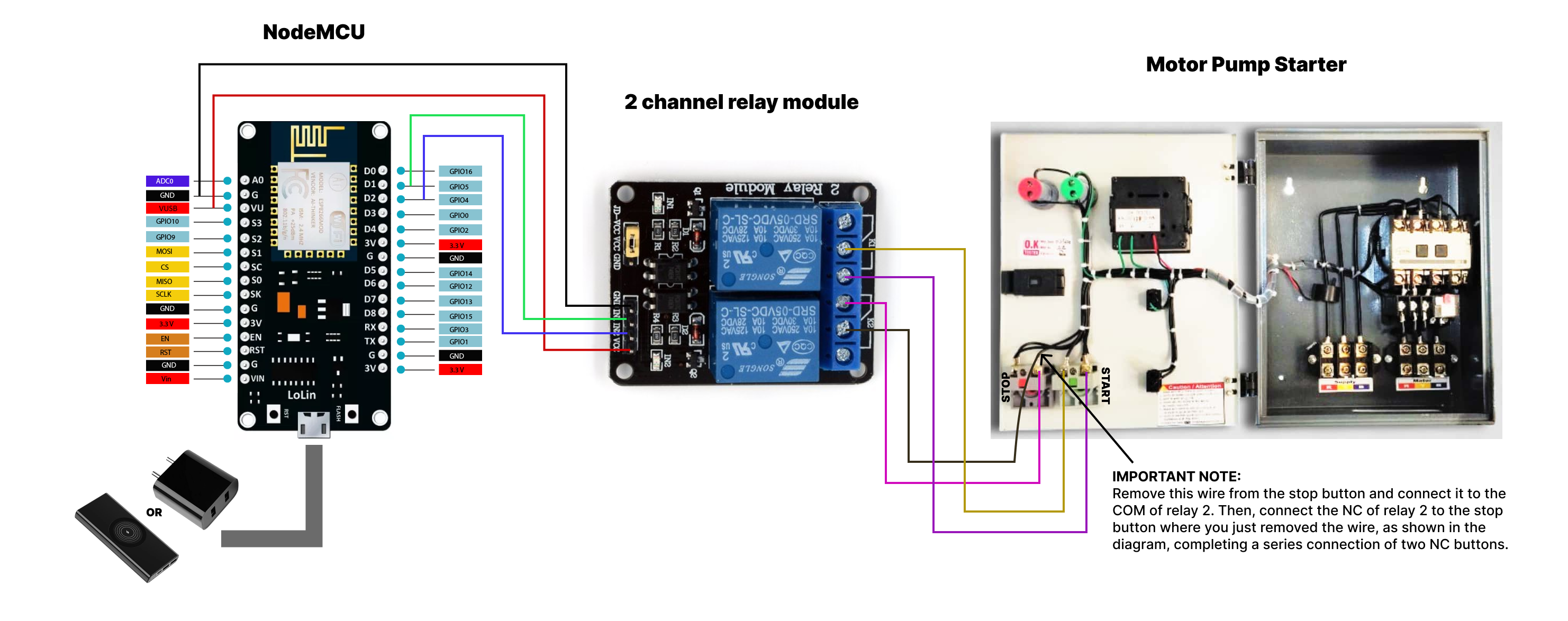
Alright, it’s time to roll up those sleeves and get down to wiring. I’ve attached a handy-dandy circuit diagram/image here. This image is your best friend—refer to it throughout this step. It’s got all the details, from NodeMCU to the relay to the motor starter.
Powering the Relay Module:
Here’s where things get a bit interesting. NodeMCU runs on 3.3 volts, but our relay module is craving 5 volts. What’s a DIY enthusiast to do?
- Option 1: Use the VU Pin
- NodeMCU’s VU Pin: This pin provides the 5V power from your USB or mobile charger to external devices like our relay module. This is usually the easiest solution.
- Why Not 3.3V? I tried using the 3V output from NodeMCU. The LED indicators on the relay module were lighting up, but the relays weren’t switching. So, I opted for the VU pin to ensure everything works as it should.
- Option 2: External Power Supply
- If you’re feeling adventurous or want to keep things super reliable, you can use an external 5V power supply for your relay module. But let’s keep it simple and use the VU pin!
Connecting Everything:
Here’s how we wire things up:
- Powering the Relay Module:
- NodeMCU VU Pin to Relay Module VCC: This gives your relay module the 5V it needs to operate.
- NodeMCU GND to Relay Module GND: A common ground is essential for proper operation.
- Controlling the Relays:
- NodeMCU D1 (GPIO 5) to Relay Module IN1: This will control Relay 1 (for the green start button).
- NodeMCU D2 (GPIO 4) to Relay Module IN2: This will control Relay 2 (for the red stop button).
Connection Summary:
Here’s a quick rundown of the connections:
- NodeMCU VU → Relay Module VCC
- NodeMCU GND → Relay Module GND
- NodeMCU D1 → Relay Module IN1
- NodeMCU D2 → Relay Module IN2
We’re done with the DC wiring! Now, let’s get ready for the final and slightly more electrifying part—connecting the relays to your motor starter switches. Brace yourself, it’s going to be a wild ride!
Getting Down to the AC Shenanigans!
Alright, folks, enough with the light-hearted banter! We’re about to get serious and dive into the electrifying world of Alternating Current—thanks to the likes of Nikola Tesla, Hyppolite Pixii, and Michael Faraday.
⚠️ Warning: ⚠️
MAKE SURE YOUR RELAY MODULE IS INSULATED PROPERLY BEFORE PROCEEDING. Also, ensure your motor starter is turned OFF.
DO NOT REPEAT MY MISTAKE (which we might discuss in a future chapter if one happens to come along). Safety first!
Wiring the Relays to Your Motor Starter:
1. Connecting Relay 1 (Start Button):
- Open your motor starter and locate the green start button. It has two input terminals.
- Wire from COM (Common) of Relay 1: Stretch a wire from this terminal to one of the inputs on the green start button. Screw it tightly along with the existing wire(s).
- Wire from NO (Normally Open) of Relay 1: Connect this to the other terminal of the green start button. Screw it in tightly.
- This way we connect relay 1 and start button parallelly.
What’s Happening Here?
- When Relay 1 is activated, it closes the circuit momentarily, just like pressing the green start button. This will turn on your motor. Plus, with this setup, you still have the option to manually operate the motor if needed.
2. Connecting Relay 2 (Stop Button):
Alright, here comes the fun part. Remember how the red stop button in the motor starter is actually a Normally Closed (NC) button? We can't simply make the same parallel connection as we did with the start button and relay 1. So, how do we connect two NC buttons while ensuring that activating either one accomplishes the task?
Yes, you guessed it! We connect them in series. Refer to the diagram in Step 3, where I’ve clearly shown how to make a series connection between the stop button and relay 2.
Here’s what you need to do:
- Remove one of the wires connected to the stop button of the motor starter and connect it to the COM of relay 2.
- Connect the NC of relay 2 to the same terminal on the red stop button from which you just removed the wire.
What’s the Deal Here?
- When relay 2 is activated momentarily, it opens the stop button’s circuit briefly, stopping the motor. Essentially, it’s like pressing the red stop button.
And that’s it!
You’ve successfully wired up your motor starter to be controlled remotely. Kudos to you for making it this far! Now, you can control your motor from anywhere using your smartphone, while still retaining the option for good old-fashioned manual control.
Bonus Tip: Use an MQTT Dash App for Quick Control!
Instead of heading to the Adafruit IO website every time, why not make things even handier? You can install any MQTT dash app like this one and configure it with your Adafruit IO account.
Steps to Set Up the App:
- Add a New Broker:
- When you start the app, add a new broker. Give it any name and client ID.
- URL: io.adafruit.com
- Port: 1883
- Check the authorization box, and enter your Adafruit username and key.
- Leave the other settings as they are.
Adding a Widget:
- Create the Button Widget:
- After connecting to the Adafruit broker, it's time to add the two buttons to this dashboard. No need to add a feed—Adafruit’s feed will be used. Click the + and tap Create Widget. Give it a name.
- Widget Parameters:
- Select your widget type—choose Button in this case.
- Name it, say ON.
- Topic: This is crucial. Type it correctly to connect to your Adafruit feed:
- <your_username>/feeds/<name_of_your_feed_on_adafruit>
- Example: testuser/feeds/motor-control
- Set Values:
- Pressed Value: 3
- Not Pressed Value: 1
- Create the OFF Button:
- Follow the same steps, but set the pressed and unpressed values to 4 and 2, respectively.
Woohoo! Now you can control your motor directly from the app, no need to open a browser. Happy controlling!
Update: Alexa Integration for Voice-Controlled Motor Pump!
Exciting news for all you automation enthusiasts! Now, you can control your motor pump with just your voice using Alexa! Whether through your Amazon Echo Dot or the Alexa app on your phone, you can simply say:
- "Alexa... Motor on" to start the motor
- "Alexa... Motor off" to stop the motor
I've uploaded an extended version of the original code to the same GitHub repository. This new file adds Alexa support, allowing for seamless voice commands.
Check out the code here:
[UPDATE] Motor Pump Controller version 2
Steps to Set Up Alexa Control
- Upload the New Code
- First, upload the new code to your NodeMCU as you did with the original project. The new code is designed to integrate seamlessly with Alexa.
- Add NodeMCU to Alexa
- Open the Alexa app on your mobile device.
- Sign in or sign up if you haven’t already.
- Go to Devices > + > Add Device.
- Select Light > Other > Wi-Fi > Discover Devices.
- Let Alexa Discover Your Device
- Alexa will take a moment to scan and discover your NodeMCU. Once it’s done, your setup is complete!
Now you’re ready to control your motor pump by voice—whether using an Echo Dot or just the Alexa app! 🎉
Time to Get Even Lazier: Automate Everything!
Now that we're controlling our motor with a smartphone, it’s time to embrace our inner couch potato—because why not? If the idea of even using your phone feels like too much work, let's talk about full automation. While I might dive deeper into this in another lesson, here’s a sneak peek:
- Manual ON, Automatic OFF:
- In our home, we’ve got this obnoxious alarm that blares when the water tank is full. If you’ve got something similar, why not put it to good use? Try connecting the alarm to the second relay that turns the motor off. Proper wiring from the alarm to the relay could automatically close the STOP circuit when the alarm goes off. Manual ON and automatic OFF—sounds efficient, right? Hear me out.
- Automatic ON, Automatic OFF:
- Our alarm works via a floater switch in the tank, which only triggers when the water level is at its max. It’s off otherwise. Now, if we connect this switch to our system, the motor would kick on every time the water level drops even a bit, turning the pump on and off hundreds of times a day. That’s definitely not what we want! This is why we’d need a second floater to signal the water level more accurately. But let’s save that for another chapter, shall we?
- Water Level Indicator: Because Who Doesn’t Love a Bit of Extra Nerdiness?
- Alright, so you’ve got your motor under control, but why stop there? Let’s level up your laziness—err, I mean efficiency—with a water level indicator! Picture this: you, lounging on your couch, knowing exactly how much water is in your tank without moving a muscle. Sounds dreamy, right?
- To make this happen, you’ll need to take a quick trip to the terrace and install a water level indicator in your tank. Now, before you start panicking about the options, here’s a handy article that rounds up the best water tank level sensors: Best Water Tank Level Sensors.
- I’m personally a fan of the ultrasonic one. But feel free to explore and find the one that tickles your fancy.
- And hey, if you’re feeling particularly adventurous, why not take it up a notch? How about developing a webpage that not only shows the water level but does so with a slick animation of water rising and falling in a tank? SO cool, right? 🌊
Feel free to reach out if you have any questions or run into issues. Happy tinkering!
Reach Out:
If you enjoyed this tutorial or have any questions, feel free to reach out! You can check out more of my work on my GitHub or visit my personal website. I’m always excited to connect with fellow makers and tinkerers!
By Kaustubh
(Kaustubh Dubey)