ESP8266 ADC - Multiple Analog Sensors
by breagan22 in Circuits > Microcontrollers
183092 Views, 167 Favorites, 0 Comments
ESP8266 ADC - Multiple Analog Sensors
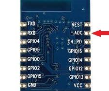
Although the ESP8266 -07 and -12 only have one ADC pin, it doesn't mean that you are limited to only one analog sensor per module. You can use many!
However, in order to use multiple sensors you will need to 'multiplex' the sensors. Multiplexing simply means that you will turn a sensor on, read the sensor, then turn the sensor off then move to the next sensor.
Here is a quick, down and dirty Instructable that should get you started with multiple analog sensors.
Lets begin!
Connect Your Sensors.
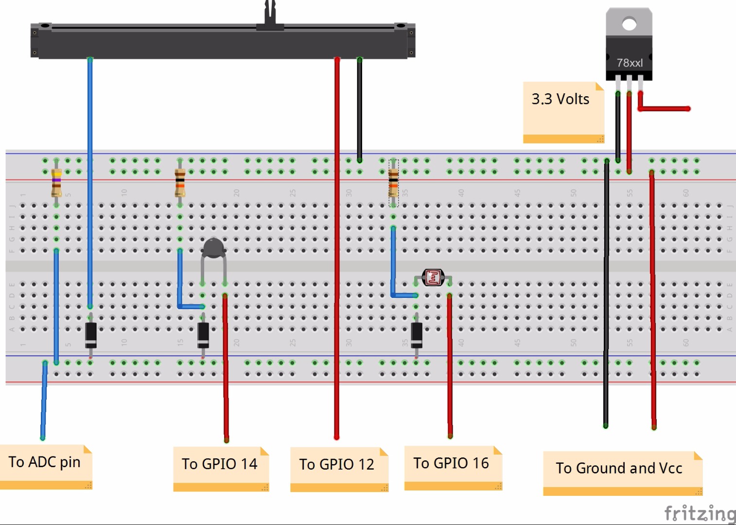
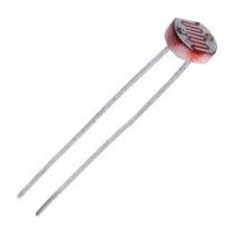
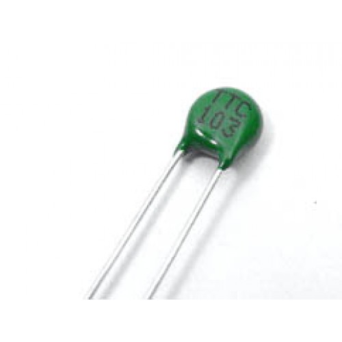
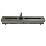
For this project I am using three analog sensors. A photoresistor, a thermistor and a sliding rheostat.
These are what I had in the parts box. Feel free to substitute.
I used:
ESP8266-12, a -07 will also work. Three available GPIOs are needed for this project.
ESP Flashed with NodeMCU, required for this demo.
2 10K resistors
1 680R resistor
3.3v voltage regulator (if necessary)
1 Photoresistor (LDR)
1 10K Thermistor
1 10K Slider
3 Diodes (I'm using 1N4007s)
The values of the resistors used are dependent on the analog sensors. Notice I am using no resistor with the slider.
There is considerable trial and error in setting this up, trim pots come in very handy.
The Diodes are the key to isolating the sensor circuits not being read. Diodes restrict current to one direction. Without diodes the sensors still work, however they interact with each other. For instance, shining a light on the LDR will raise the value at its GPIO, however it will also reduce the value of the other sensors. Diodes isolate the circuits.
The Multiplexing Script.
In order to multiplex, only one sensor can have a complete circuit at a time. By setting the the GPIO to HIGH, we are sending ~3.0v to that sensor and completing the circuit. The others, being set to LOW send no voltage. This essentially creates a ground to ground connection. No current.
After we send the voltage, we read the ADC pin and print out the value. We can also save that value in a variable.
This code 'var1 = adc.read(0)' will work. We can then manipulate the value and convert as required.
After we read or save the reading from the sensor, we turn it off and move to the next sensor.
The delay is not necessary, but it makes me feel better.
All the GPIOs being used with analog sensors should be set to LOW except when reading them.
There is no special reason for using GPIOs 16, 14 and 12. Any three would do. Avoid using GPIO0.
___________________________________
-- multisensor.lua
-- ---------------
--configure pins
gpio.mode(0,gpio.OUTPUT) -- GPIO 16
gpio.mode(5,gpio.OUTPUT) -- GPIO 14
gpio.mode(6,gpio.OUTPUT) -- GPIO 12
--set all pins to LOW - no voltage
gpio.write(0,gpio.LOW)
gpio.write(5,gpio.LOW)
gpio.write(6,gpio.LOW)
-- print the ADC value with all pins low
print("\nADC: Both GPIOs LOW start: "..adc.read(0))
-- Send voltage to GPIO 16 completing the circuit for this sensor.
gpio.write(0,gpio.HIGH)
-- short delay before reading, 100ms
tmr.delay(100000)
-- Read the ADC pin or assign to varable var = adc.read(0)
print("\nADC: GPIO 16 HIGH LDR: "..adc.read(0))
-- Return GPIO 16 to LOW, no voltage.
gpio.write(0,gpio.LOW)
-- short delay 100ms
tmr.delay(100000)
-- repeat for the other two sensors.
gpio.write(5,gpio.HIGH)
tmr.delay(100000)
print("ADC: GPIO 14 HIGH Temp: "..adc.read(0))
gpio.write(5,gpio.LOW)
tmr.delay(100000)
gpio.write(6,gpio.HIGH)
print("ADC: GPIO 12 HIGH Slider: "..adc.read(0))
gpio.write(6,gpio.LOW)
-- again read ADC, this reading should be very close to the 'start reading'
print("\nADC: Both GPIOs LOW end: "..adc.read(0))
Fine Tuning.
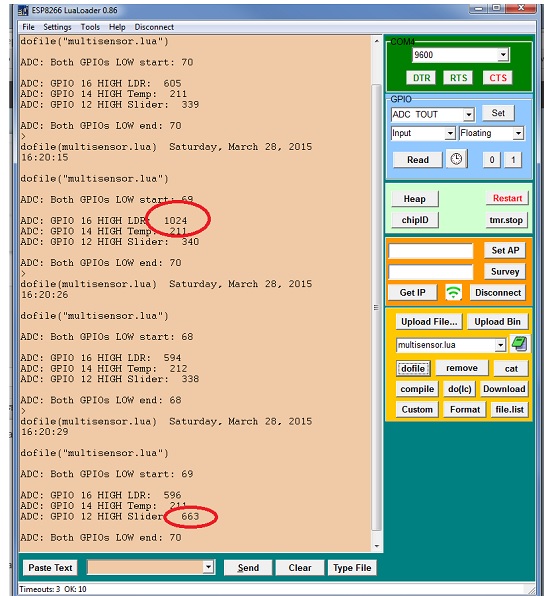
Upload this script to your ESP and 'dofile'.
You should see values for the sensors! Each time you run the script the sensors are read and the results printed.
I put a flashlight on the LDR and ran the script. The LDR registered 1024. In the last run I had moved the slider.
As I mentioned earlier, finding the right combination of resistor values is crucial. Keep in mind that adding sensors, including diodes and resistors will alter the voltage across other sensors. This will test your 'Tweak and peak' skills.
There is a discussion about voltage and voltage measurements at the ADC pin here:
https://www.instructables.com/id/ESP8266-ADC-Analog-Sensors/
For those of you reading this that possess advanced electronics skills and are able to calculate correct values for these variables, I applaud your skills and apologize for my lack of knowledge! Perhaps you can share with us?
So, here is a good jumping off point. Thank you for reading this and good luck with your projects!