ESP8266 Programming Using FTDI and Arduino IDE
by nkotzalas in Circuits > Wireless
49963 Views, 65 Favorites, 0 Comments
ESP8266 Programming Using FTDI and Arduino IDE
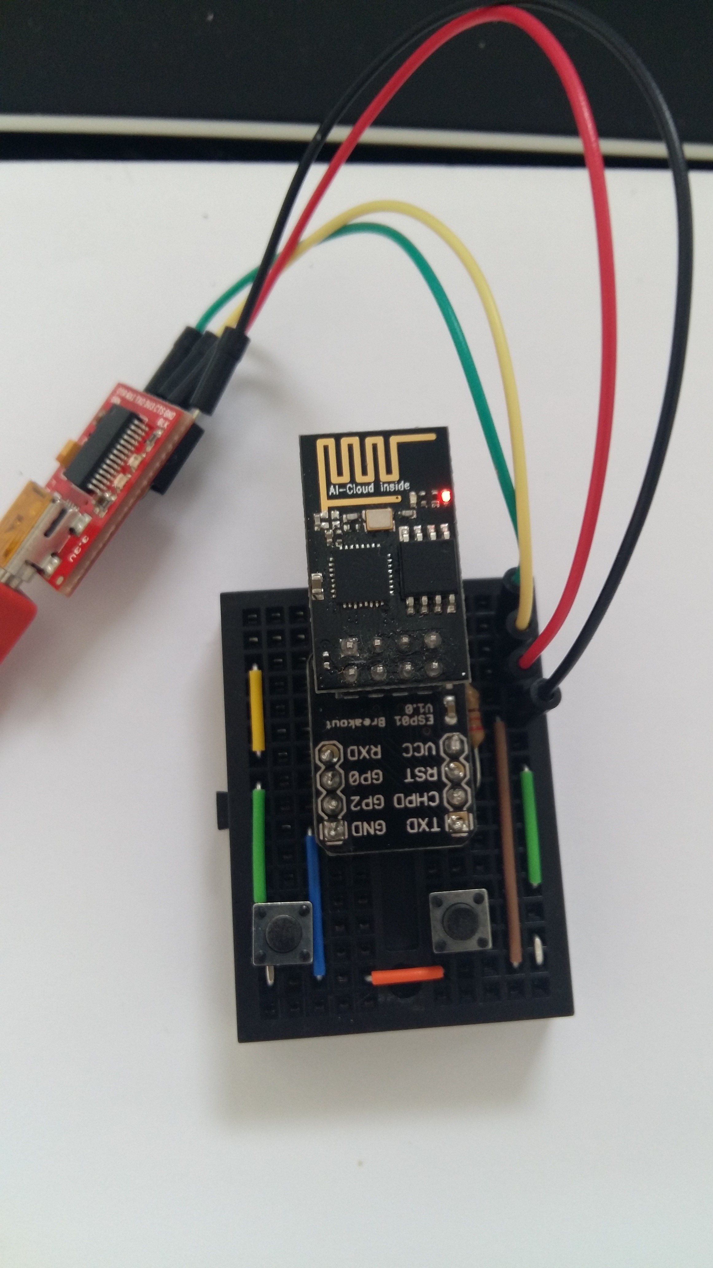
When I first tried to use an ESP8266 (01), I was really excited to work with the module. However, I found it really hard to get started. Coming from an Arduino background, I wanted to program the module using the Arduino IDE, since I knew that it is possible. Although there are many good tutorials in the web for doing this, none of them worked for me out of the box.
Dwelling a bit more in depth in how the module works, I realized that although it can be programmed using the Arduino IDE, there is a major difference in how you work when uploading sketches to an ESP-01 and an Arduino. Arduinos are always in a mode that allows you to upload sketches to them. However, this is far from the case with ESP8266. In order to upload a sketch to ESP-01, you must first set it in programming mode. To do so, one must apply the following steps:
- Power the module (3.3 Volts)
- Connect the RESET pin to the GND
- Connect the GPIO-0 pin to the GND
- Disconnect the Reset pin from the GND
- Disconnect the GPIO-0 pin from the GND
- Upload your sketch
Despite having to remember all these steps every time you need to change something in your code, this approach entails another problem as well. If the circuit that you are working on requires connecting GPIO-0 to the grounding somehow (e.g. connecting a LED to GPIO0), you are then forced to change your circuit every time that you need to make even a minor change to your sketch! I found this approach very unproductive. In my point of view, the only productive way to work with the module is to have a separate circuit for programming the ESP8266 and another for the component under implementation. This instructable shows how to make a component that allows you to program the ESP-01 easily, using the Arduino IDE. To hack the component, you need to have the following:
- ESP8266 (01)
- ESP8266 breadboard adapter (or a custom made alternative, since the module is not breadboard friendly)
- 3.3 Volt FTDI cable (or any other 3.3 Volt FTDI)
- 1 Mini solderless breadboard (or any other breadboard)
- 2 mini push buttons (with 2 pins each)
- A 220 Ohm Resistor
- A few jumper wires
Create the Circuit on the Breadboard
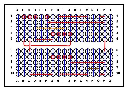
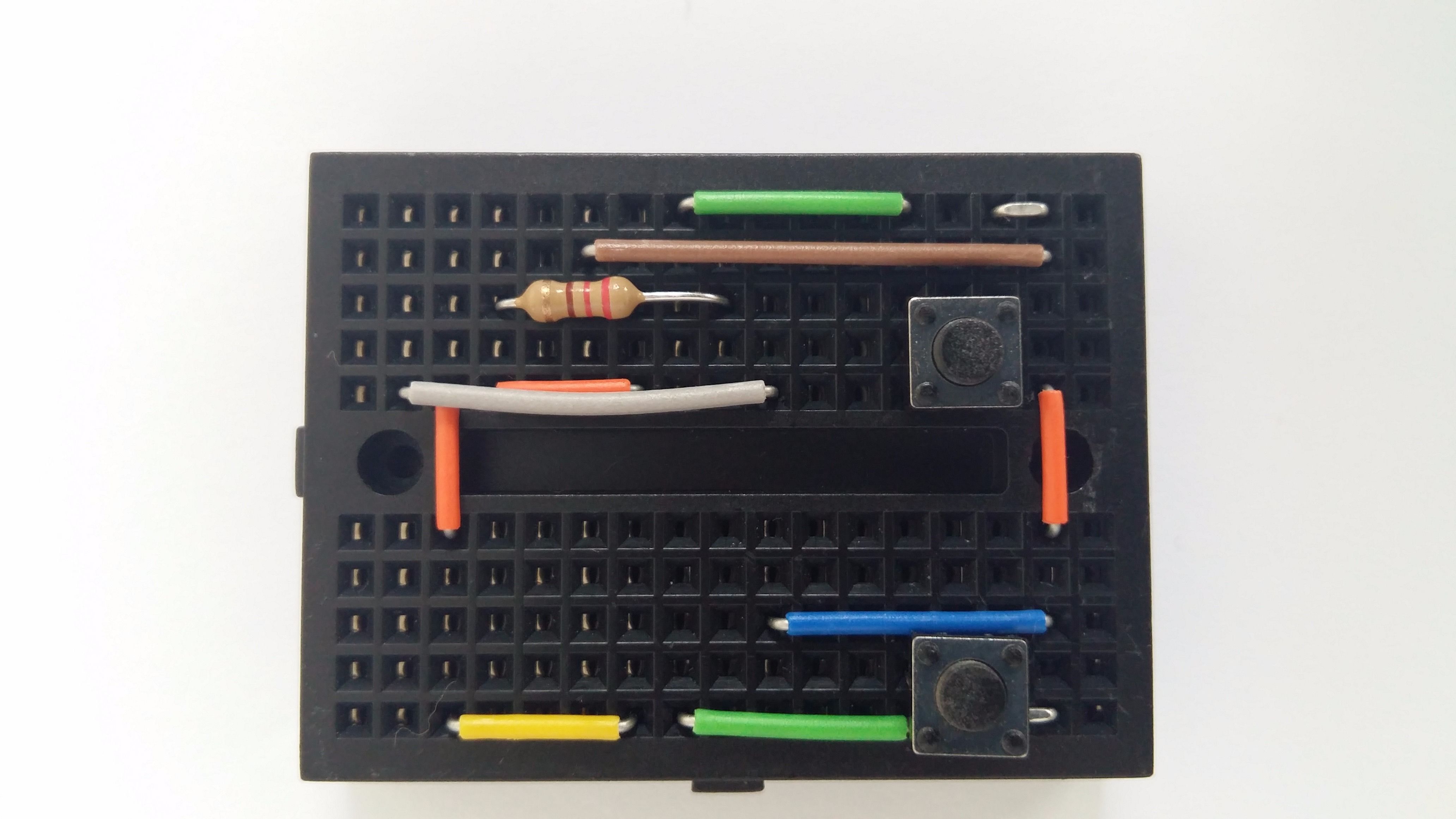
I am assuming that you have a mini solderless breadboard as the one described in the previous section. The first picture in this step contains a diagram of the breadboard, in which every pin is identified by a character (vertical) and a number (horizontal), pretty much in the same way as squares are mapped in a chessboard. The diagram also depicts the final circuit, showing which pins must be connected. To create the circuit you must apply the following connections:
- O1 --> P1 (wire)
- O10 --> P10 (wire)
- P5 --> P6 (wire)
- J8 --> P8 (wire)
- H10 --> M10 (wire)
- C10 --> G10 (wire)
- C5 --> C6 (wire)
- D5 --> G5 (wire)
- B5 --> J5 (wire)
- H1 --> M1 (wire)
- F2 --> P2 (wire)
- D3 --> I3 (220 Ohm resistor)
- M4 --> O4 (Push button)
- M9 --> O9 (Push button)
Connect ESP8266 and Jumper Wires
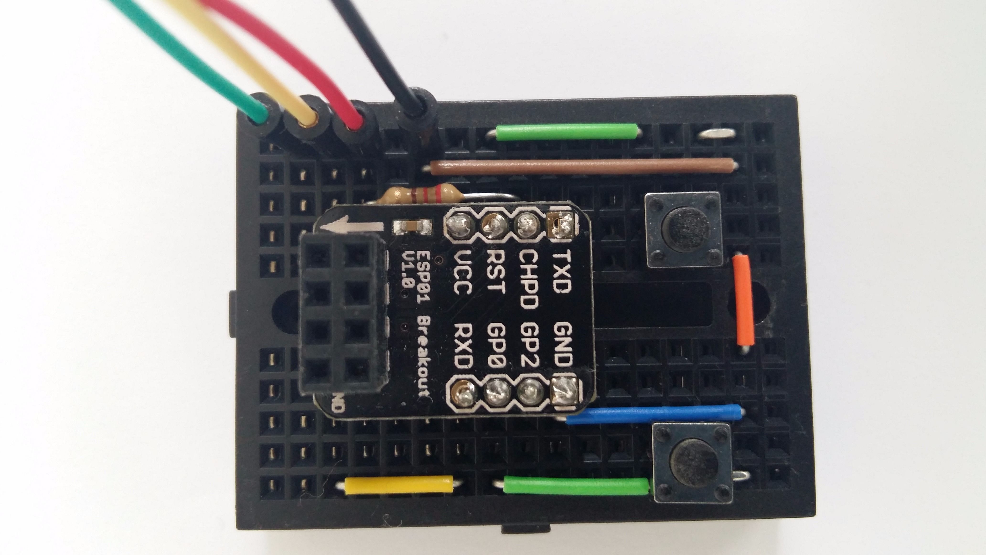
Connect the ESP8266 to the breadboard so that the following apply:
- ESP VCC --> G4
- ESP RST --> H4
- ESP CHPD --> I4
- ESP TX --> J4
- ESP RX --> G7
- ESP GPIO0 --> H7
- ESP GPIO2 --> I7
- ESP GND --> J7
Also add the following Jumper wires:
- Green wire --> B1 (ESP TX)
- Yellow wire --> C1 (ESP RX)
- Red wire --> D1 (ESP VCC)
- Black wire --> F1 (ESP GND)
Connect the FTDI and ESP8266 to the Circuit
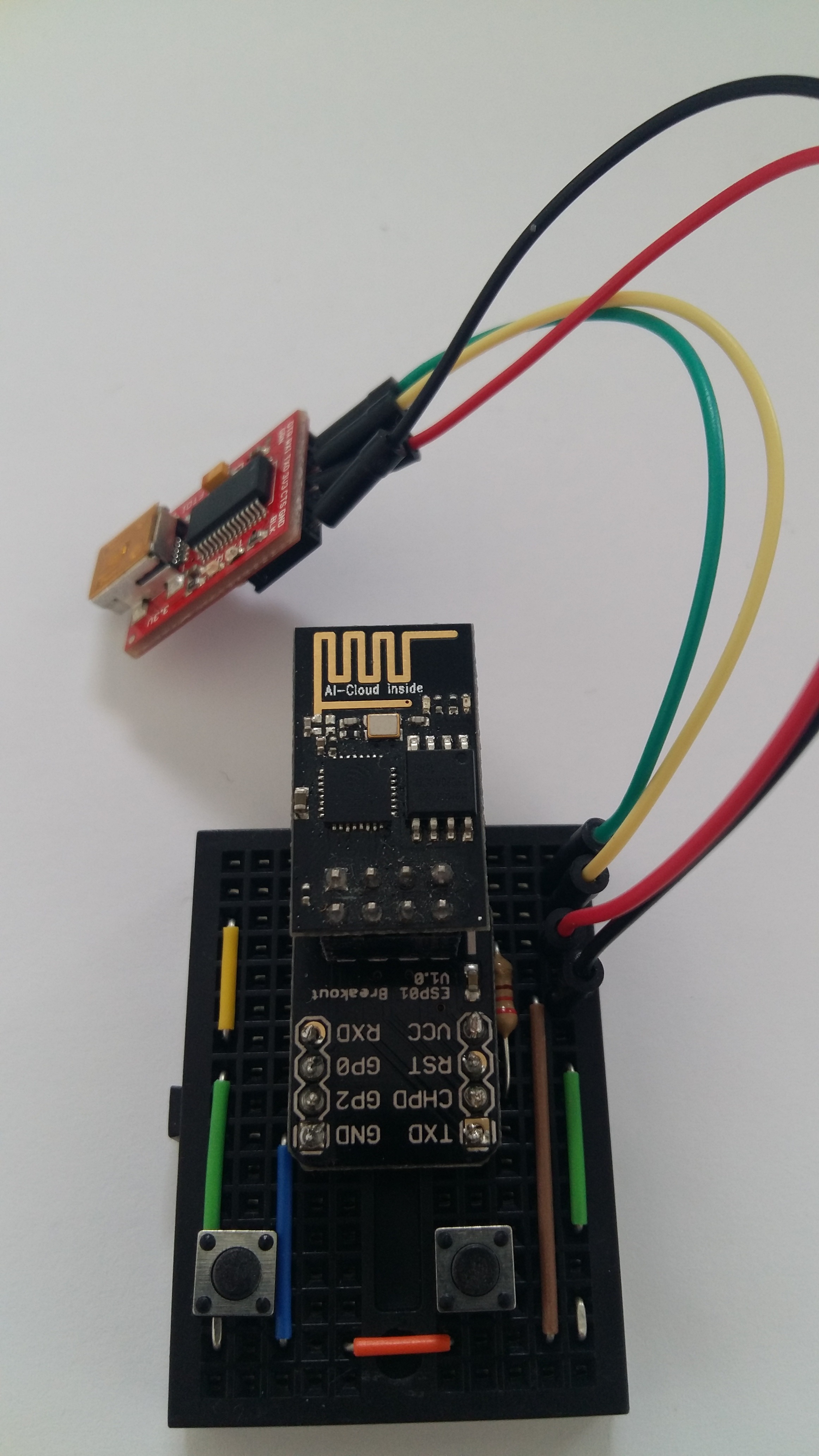
Connect the FTDI component so that:
- The TX of the ESP8266 is connected to the RX of the FTDI (i.e. green wire)
- The RX of the ESP8266 is connected to the TX of the FTDI (i.e. yellow wire)
- The VCC of the ESP8266 is connected to 3V3 of the FTDI (i.e. red wire)
- The GND of the ESP8266 is connected to the GND of the FTDI (i.e. black cable)
Also connect the ESP8266 so that the golden lines of the component will point to the opposite direction from the one in which the buttons are
Connect to Your PC and Set Up Programming Mode
Connect the FTDI to your PC through a USB port. The red led of the ESP module will switch on.
The button on the side of the breadboard in which the jumper wires are located is the reset button, while the other button is the one that grounds the GPIO0.
- Press the reset button and keep it pressed.
- Press the GPIO0 button and keep it pressed.
- Release the reset button
- Release the GPIO0 button
If a blue light will switch on momentarily on the ESP module, then your ESP is in programming mode.
Upload Your Sketch
Add ESP8266 as a board in the Arduino IDE (as described here).
In the Arduino IDE, under Tools --> Board, select "Generic ESP8266 Module".
Select the port in which the ESP module is connected.
Upload an empty sketch to your ESP module and check if the progress of uploading is displayed in the console of the Arduino IDE (should display the progress in orange color). If so, you can now write any sketch you want and program your ESP8266 easily.