ESP8266 MPSM V.2 DevBoard - MAINS WIFI Web Power Switch
by TrackerJ in Circuits > Microcontrollers
23749 Views, 191 Favorites, 0 Comments
ESP8266 MPSM V.2 DevBoard - MAINS WIFI Web Power Switch

WARNING!! You will play with LIVE MAINS!! Deadly zone!!
If you don't have any experience and are not qualified for working with MAINS power I will not ecourage you to play arround!
Do NOT use it without proper Knowledge about MAINS circuits !
Do NOT use it without a proper FUSE on MAINS line!
This is NOT a Toy!
-------------------------------------------------------------------------------------------------
Remember the story about the WIFI MAINS Power Switch module?
Because of the high interest in the subject, a new dedicated Dev Board has been born: MPSMv2, a small ESP8266 DevBoard with integrated MAINS Power Switch!
I don't know if this it's the smallest MAINS Power Switch with integrated WIFI and direct Web interface access but if is not, it's definitely closer to be at only around 25x50mm :)

Schematic and Theory of Operation

Main Power Switch Module (MPSM)
General considerations:
For resistive loads ON-OFF only jobs (no dimming required) a winning combination is between MOC304X for Triac driver (Zero voltage crossing one) and a good quality Triac, decently sized by the power needs. A 25A one usually fits mostly of the needs in a domestic project, with proper heatsink for power disipation. For standard home lighting, 8A is 99% of the times more than enough for one channel. If your house is a Castle with huge chandeliers, probably not :).
Triacs are the most common used semiconductor devices for power control and switching applications. Such power control circuits can be used to remotelly switch power to electrical devices or to switch power automatically when parameters such as temperature or light intensities go beyond preset level.
BT1XX class from NXP never dissapointed. Be sure they are genuine, from a trustable source. I know, shit happens in the supply chains even to big houses from time to time but, as a good practice, a good traceability for the parts you are using is desirable.
And don't forget :LIVE MAINS Switching!!
A typical circuit for use when hot line switching is required:

In this circuit the “hot” side of the line is switched and the load connected to the cold or neutral side. The load may be connected to either the neutral or hot line.
This type of circuit from above is good enough for resitive loads only. When a TRIAC controls inductive loads, the mains voltage and the load current are not in phase. To limit the slope of the reapplied voltage and ensure right TRIAC turn-off, usually is used a "snubber circuit" connected in parallel with the TRIAC. This circuit can also be used to improve TRIAC immunity to fast transient voltages.

The 100Ω resistor and 0.01μF capacitor are for snubbing of the triac and is often, but not always,necessary depending upon the particular triac and load used, generally for inductive ones.
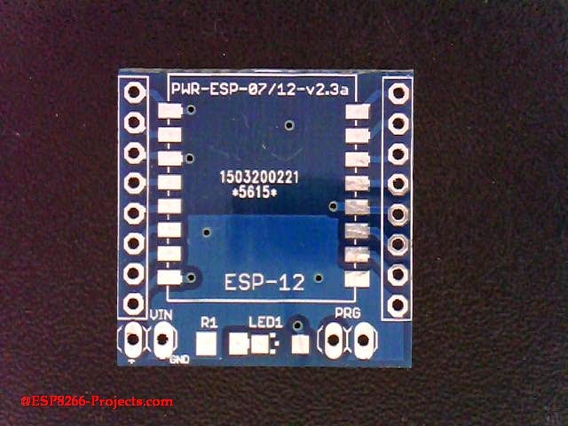
PCB Details

As you can see from the pictures below MPSMv2 DevBoard PCB was designed with great flexibility in mind.
You have even a full ESP8266 pinout access thru 2 breadboard friendly expansion slots for future projects development.

If you want to have a separate Breadboard friendly ESP8266 adapter with integrated 3.3V Power Supply, you can cut the board in 2 independent working parts, the ESP07/12 adapter and the MAINS Triac Switch.
It is designed in such way that no harm will be done by the cut to the functioning of the circuit. You can use the cut MAINS Power Switch part directly even with your ARM, PIC, Atmel, Arduino, whatever MCU you like this days without any problems as long as it has a GPIO pin capable to drive the MOC Optocoupler LED.

What We Will Need
- MPSM DevBoard presented in this article
- USB adapter (take a look on CBDB Part 1 for details how to connect them together)
- NodeMCU firmware (download latest - I recommend you to use the floating point version)
- NodeMCU Flasher ( firmware programmer for NodeMCU DEVKIT)
- For programming MPSM v2 DevBoard and uploading the software we will continue to use the LuaUploader as before.
If your Firewall/AV have reported strange behaviours of NodeMCU Flasher, might be a good idea to read about the callback issue. Looks like nothing harmful, just annoying.
Firmware

Flashing the MPSM NodeMCU Firmware is a straigth away process:
- Connect MPSM Board with the USB Adapter, Set the PROG jumper (YELLOW) in the Programming mode position (closed) and power on
- Start NodeMCU Flasher. Choose you USB adapter corresponding port
- Add from Config Menu latest previously downloaded firmware. It must start from 0x0000. Disable anything else.
- Go back on Operation tab. Power off your MPSM Board. Press FLASH Button. power ON quick MPSM Board. It will be recognised and will start flashing. Give it a second try if necessary.
- When finished succesfully A green OK checkmark will appear
- Power Off MPSM Board, Remove yellow jumper. Power back ON. A NodeMCU programmed MPSM Board is ready for action :)
For a more detailed explanation for NodeMCU Firmware flashing please take a look at CBDB Board Firmware Flashing discussion
Testing MPSMv2 Board

To do quick run test we will use the code snippets provided by LuaUploader at start-up. Select the piece of code that you want to run and press "Execute Selection" button.
- WIFI network Setup - If this is your first project with a new ESP module that was never used in your WIFI Network, don't forget it - one time only :
 -- One time ESP Setup --
     wifi.setmode(wifi.STATION)
     wifi.sta.config ( "YOUR_WIFI_SSID" , "PASSWORD" )
print(wifi.sta.getip())- For the Triac Optocoupler Command testing we will use the "Blinky" part of the code and if all ok it will blink LED2 with the choosen rate "dly". Run the modified code from below:
     -- Blink using timer alarm --
          timerId = 0 -- we have seven timers! 0..6
          dly = 500 -- milliseconds
          ledPin = 1 -- 1=GPIO5  - allocated pin for Triac opto command
          gpio.mode(ledPin,gpio.OUTPUT)
          ledState = 0
          tmr.alarm( timerId, dly, 1, function()
                ledState = 1 - ledState;
                 gpio.write(ledPin, ledState)
          end)
If all OK Now you can carefully power off all and connect you MAINS powered lightbulb. Repeat the testing stepts from above and you can see it also playing the "Blinky" game too :). Use proper heatsink for power disipation for your Triac.
MAINS Power Switch Software

Power Switch function and WEB Server software are more or less the same as in previous article about CBDB WIFI MAINS power switchwe will just change the used GPIO pin for Triac opto command pin from outpin=3 to outpin=1 to properly reflect our new MPSM v2 Board configuration.
For programming MPSMv2 Board and uploading the driver and the software we will continue to use the LuaUploader as before.
- Define used GPIO pin:
   outpin=1       -- Select Triac command PIN - GPIO5
   gpio.mode(outpin,gpio.OUTPUT)
   gpio.write(outpin,gpio.LOW)
- Power Switch function, acting based on received command:
function PwrSW(swstat,payload)
   gpio.mode(outpin,gpio.OUTPUT)
   newstat=string.sub(payload,swstat[2]+1,#payload)
   status = newstat
   if newstat=="ON"  then gpio.write(outpin,gpio.HIGH) return end
   if newstat=="OFF" then gpio.write(outpin,gpio.LOW) return end
end
- Send Page function based on request:
function sendPage(conn)
   conn:send('HTTP/1.1 200 OK\n\n')
   conn:send('<!DOCTYPE HTML>')
   conn:send('<html>')
   conn:send('<head><meta content="text/html; charset=utf-8"><style>input{width: 100px; height: 100px;}</style>')
   conn:send('<title>ESP8266 - Power Switch Controller</title></head>')
   conn:send('<body><h1>Power Switch Controller</h1>')
   conn:send('Status: <b>')
   if (status == "ON") then      conn:send('<B><font color=red>ON</font></B>')
   elseif (status == "OFF") then    conn:send('<B><font color=green>OFF</font></B>')
   else
      conn:send(status)
      conn:send('%')
   end
   conn:send('</b><br /><br />')
   conn:send('<form action="/" method="POST">')

   if (status == "ON") then  conn:send('<input type="submit" style="background-color:red" name="cmd1" value="OFF"/><br /><br />')
   elseif (status == "OFF") then  conn:send('<input style="background-color:green" type="submit" name="cmd1" value="ON"/>')
   end

   conn:send('</form>')
   conn:send('</body></html>')
end
- Web Server:
srv=net.createServer(net.TCP)
srv:listen(80,function(conn)
   conn:on("receive", function(conn,payload)
      --next row is for debugging output only
      --print(payload)
      if (string.find(payload, "GET / HTTP/1.1") ~= nil) then
         print("GET received")
         sendPage(conn)
      else
         swstat={string.find(payload,"cmd1=")}
         --If POST value exist, set LED power
         if swstat[2]~=nil then
            print("Command received: " .. payload)
            PwrSW(swstat,payload)
            sendPage(conn)
         end
      end
   end)
   conn:on("sent", function(conn)
      conn:close()
      print("Connection closed")
   end)
end)
Save the code on ESP as 'web_switch.lua', restart ESP and run:
  =wifi.sta.getip()        -- find the IP Address where your new Web Server will be
  dofile("web_switch.lua") -- Start the Web Server
Open your favorite Web browser and type your new Web Server IP address. If all ok, should look something like below :
If you want the Web Power Switch software to start automatically when your MPCMv2 Board starts or reboots, then you neet to create and add some lines in your 'init.lua' file:
tmr.now()                      -- for debug only, you can skip it
wifi.sta.getmac()              -- for debug only, you can skip it
wifi.sta.getip()               -- for debug only, you can skip itnode.heap()
dofile("web_switch.lua")       -- needed to start Web Server for command input
Save the code on ESP as 'init.lua', restart ESP. It should reboot and restart automatically the program and reinitialize the Web Server:

CONCLUSIONS
This is a easy to build experimental WIFI MAINS Power Switch Dev Board example for a Web Controlled Power ON-OFF switch only. Dimming is another story and we will talk about in a separate Article maybe soon :).
- Original Article link: MPSMv2 DevBoard
- If you want to order bare PBC's only, PCB Factory Direct link: MPSMv2 PCB
- For any other inquiries and requests use tech at esp8266-projects.com
If you choose to use the MPSM project hardware and/or software to do whatever experimentation you might imagine, you do so ENTIRELY AT YOUR OWN RISK.
The software and hardware designs are distributed in the hope that they will be useful, but WITHOUT ANY WARRANTY; without even the implied warranty of MERCHANTABILITY or FITNESS FOR A PARTICULAR PURPOSE.
Do NOT use it without proper Knowledge about MAINS circuits !
Do NOT use it without a proper FUSE on MAINS line!
This is NOT a Toy!