ESP8266 Aurora Projector
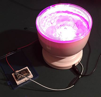
ESP8266 IoT Controlled Aurora Master Ocean Relax Projector
Overview
The Aurora Master Ocean Relax Projector http://goo.gl/ZmdWgr is an inexpensive popular LED based night special effects light. It projects softly moving colored patterns on walls or ceiling.
But one problem it has, is that it is manually controlled. This is fine for most typical uses, but for Makers, it presents itself as a candidate for Internet of Things (IoT). Using the new ESP8266 module, with its ability to built-in WiFi, processor and GPIO pins, it allows for easy wireless networking and interfacing, all for less than $10.
NOTE: THIS WILL VOID YOUR WARRANTY of the Aurora Master, but since it’s only about $15, not a great loss if you mess up. You will be modifying the Aurora Master, removing the manual buttons and soldering a couple wires. Using the ESP8266 makes for a low cost wireless add-on.
How it Works
In order to simplify the external components needed, I used the excellent Adafruit HUZZAH ESP8266 breakout instead of the more raw ESP8266 modules. This one supports 5V DC Input power directly. The same power that the Aurora Master uses.
The Aurora Master has 3 buttons to control it. Two are just for optional audio control. I don’t use its audio feature, but you can if desired.
The center button is the Power and Mode button. Each time you press it, it switches to another pattern. Pressing it several times ends up turning the unit back off. The unit also turns itself off after about an hour.
This modification allows you to “press” this Power/Mode button remotely via WiFi from any web browser or Linux Curl or Python web command. By repeatedly calling the ESP8266’s URL, you can turn the unit on, switch between patterns, or turn the unit off.
Requirements
You will need the following components. Note that because the ESP8266 GPIO pins are 3.3v while the Aurora Master is 5v, you will need an NPN transistor and 1K resistor interface.
HARDWARE
- · Aurora Master Ocean Relax Projector such as from Amazon: http://goo.gl/ZmdWgr
- · Adafruit HUZZAH ESP8266 Breakout https://www.adafruit.com/products/2471
- · NPN Transistor such as a 2N2222, 2N3392, or similar.
- · 1 K resistor
- · USB to Serial or FTDI cable for programming the ESP8266
- · Wire with breadboard plugs
- · Small breadboard
- · Ability to do soldering to small circuit board.
SOFTWARE
- · Arduino IDE with ESP8266 extension package installed
- · Download my ESP8266 Aurora Master web server app from GitHub: https://github.com/rgrokett/ESP8266_aurora_master...
-- NOTE:You can go to Github for a version of this guide:
https://github.com/rgrokett/ESP8266_aurora_master/...
Important Initial Setup of ESP8266
Before beginning the modification, you should become familiar with the Adafruit HUZZAH board and programming it using the Arduino IDE. The best way is to use the excellent Adafruit tutorial:
https://learn.adafruit.com/adafruit-huzzah-esp8266...
You must be able to program your ESP8266 and connect wirelessly to it via browser.
Once completed, THEN continue below.
Hardware Modifications
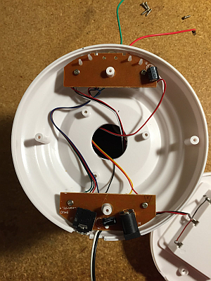
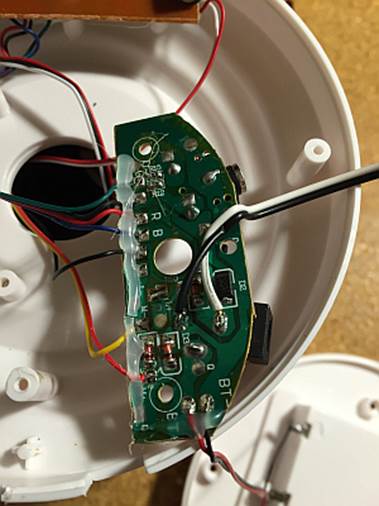
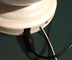
- Disassemble the Aurora Master by removing all 5 screws on the bottom, including the battery cover. Remove any batteries and use only the AC Power supply included with the Aurora Master. Since you won’t use batteries, you can safely cut the two leads to the battery holder and tape them off. (optional!)
- There are two circuit boards. One for Power and the other for Control. Remove the screws from the Power board. (bottom board in photo above).
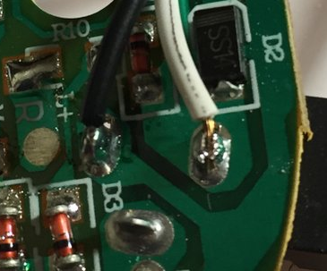
- Solder two wires about 6” long to the 5v power connector as shown in the photo below. These wires should have a breadboard pin or connector on the other end, just to make it easier to plug into a breadboard.
Black wire goes to the ground of the power connector
White wire goes to the +5V of the power connector - Cut a small groove into the plastic case beside the power connector so you can route the wires out of the case w/o crushing them.
- Replace the power circuit board and its screws.
Be SURE the BLACK and WHITE wires are NOT touching each other. These are directly connected to the 5V supply and would short it out!
Continue With Control Board Mod...
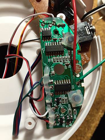
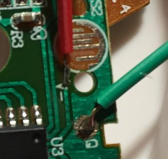
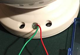
- Now remove the screws from the Control board. There are 3 plastic buttons that will fall out. You can discard them unless you plan to use the built-in audio feature.
- Remove the rubber cover of the CENTER button. You will see a tiny grid circuit pad. You will need to solder two wires to these traces. Since they are very small, you have to be very careful not to bridge the gap with solder!
I decided to solder the ground wire (GREEN) to a nearby solder pad.
And the RED wire slightly away from the grid pad.
Use an Exacto knife to delicately scrape the top of the circuit board points where you are going to solder in order remove any coating for easier soldering. I had to use a very fine solder point (0.8mm) and magnifying glass, due to the small size. Don’t overheat! - Once soldered, gently push the wires thru the center button hole to the outside of the case and replace the Control circuit board. I used hot melt glue in the hole to hold the wires.
- Replace the bottom and battery cover.
TEST
You can verify the wiring before continuing by plugging in the 5V power and momentarily connect between the RED and GREEN wires. The Aurora should turn on. Each time you touch the wires together it should cycle to the next mode just like before the modification.
You can test the Power leads (BLACK & WHITE) using a voltmeter. The White lead should be +5v and Black ground.
ESP8266 Software and Hardware
First you should program and test the ESP8266 before adding its hardware wiring.
1. STOP! Be sure you have already completed the preliminary software setup of the Arduino IDE and tested the ESP8266 with your WiFi network as described in the Initial Setup above!
2. Ok, download the ESP8266_aurora_master software from GitHub https://github.com/rgrokett/ESP8266_aurora_master...
3. Copy the WiFiWebServer.ino program to your Arduino library area.
4. Using Arduino IDE, edit the WiFiWebServer.ino and insert your SSID and PASSWORD into the appropriate places.
5. Compile and Upload the program just like shown in the Adafruit tutorial.
6. When the program finishes loading, open a Serial Monitor, set to 115,200 baud, and press the ESP8266 RESET button to restart the program running.
7. It should display its IP address once connected to your Wifi. Also, the onboard Red LED should blink 4 times signifying it’s connected.
8. Use a browser to go to http://your_ip_addr/gpio/0
This should respond back with “GPIO is now LOW” in browser
Go to http://your_ip_addr/gpio/1 and see “GPIO is now HIGH”
Go to http://your_ip_addr/gpio/step and see the onboard LED blink once
9. Unplug your ESP8266. It’s now ready.
Next Is the ESP8266 Wiring:
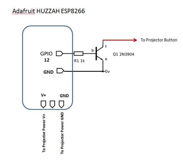
- See the diagram of the wiring for the transistor and resistor.
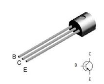
- And the leads for the NPN transistor
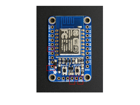
- The third photo shows the pinout of the HUZZAH ESP8266 with the connection points marked.
The Power leads (WHITE to V+, BLACK to GND)
The Control lead (RED to GPIO pin 12)The other control lead (GREEN) does NOT have to be connected, as the Power ground is sufficient.
Finishing Up the Hardware
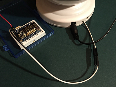
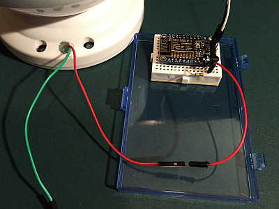
Once the wires are all connected, it should look like the photos.
1. Plug the Aurora Master power supply in and watch for the ESP8266 Red LED to blink 4 times indicating it connected to your WiFi network.
2. Use a browser and Go to http://your_ip_addr/gpio/step and see the onboard LED blink once and the Aurora turn on.
3. Repeat the above URL multiple times to step thru the patterns and finally turn off.
4. If you have a Linux server or Raspberry Pi, you can use the tiny shell scripts to control it:
$ sh on.sh -- Turns on the Aurora
$ sh off.sh -- Step thru to turn off the Aurora
Now, have fun remotely controlling your Aurora Master projector!
FINISHED!