ESP8266-01 Lighting 2 LEDs From Anywhere in World Using Blynk App
by Shrijeet in Circuits > Wireless
5506 Views, 37 Favorites, 0 Comments
ESP8266-01 Lighting 2 LEDs From Anywhere in World Using Blynk App
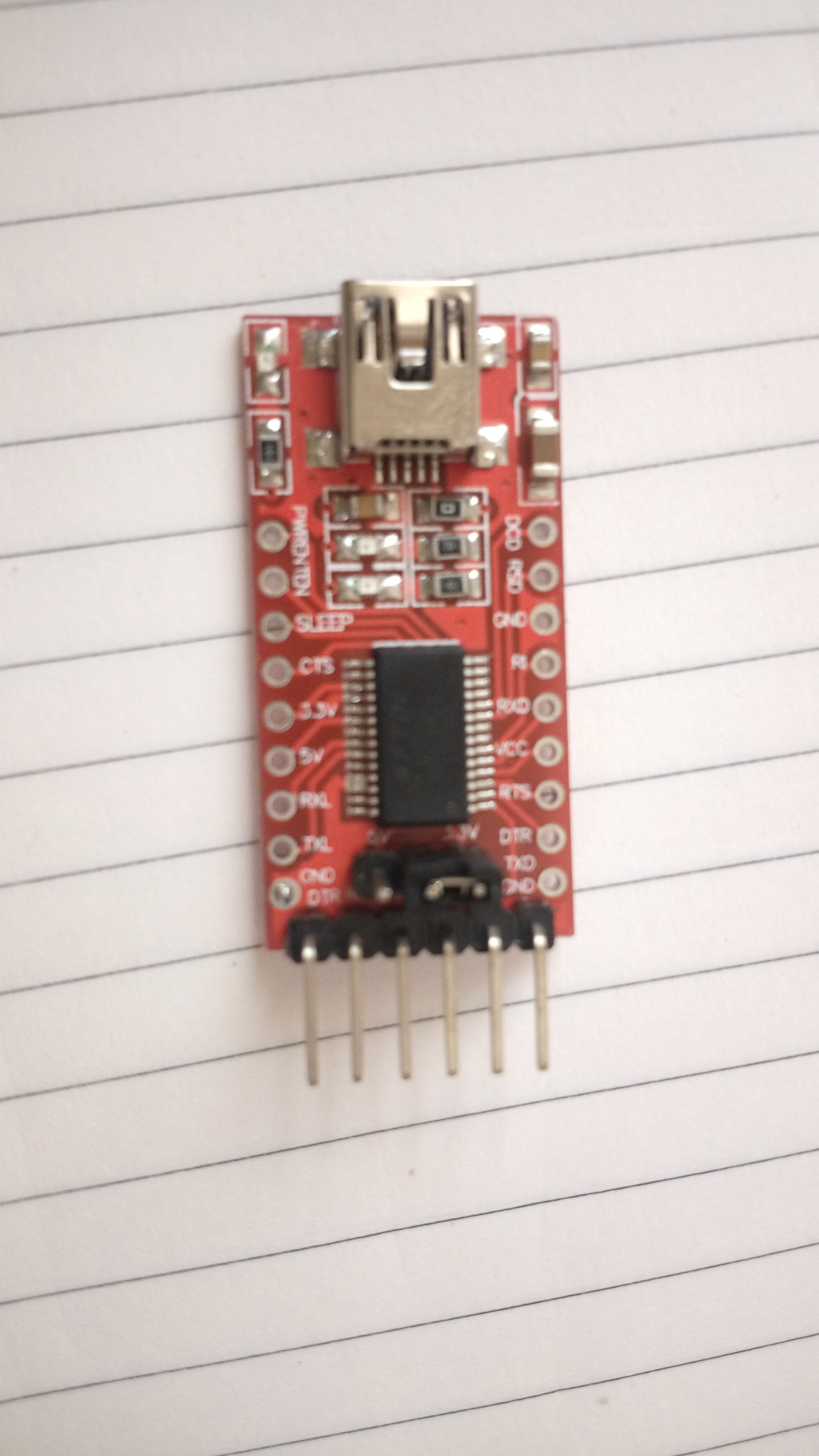
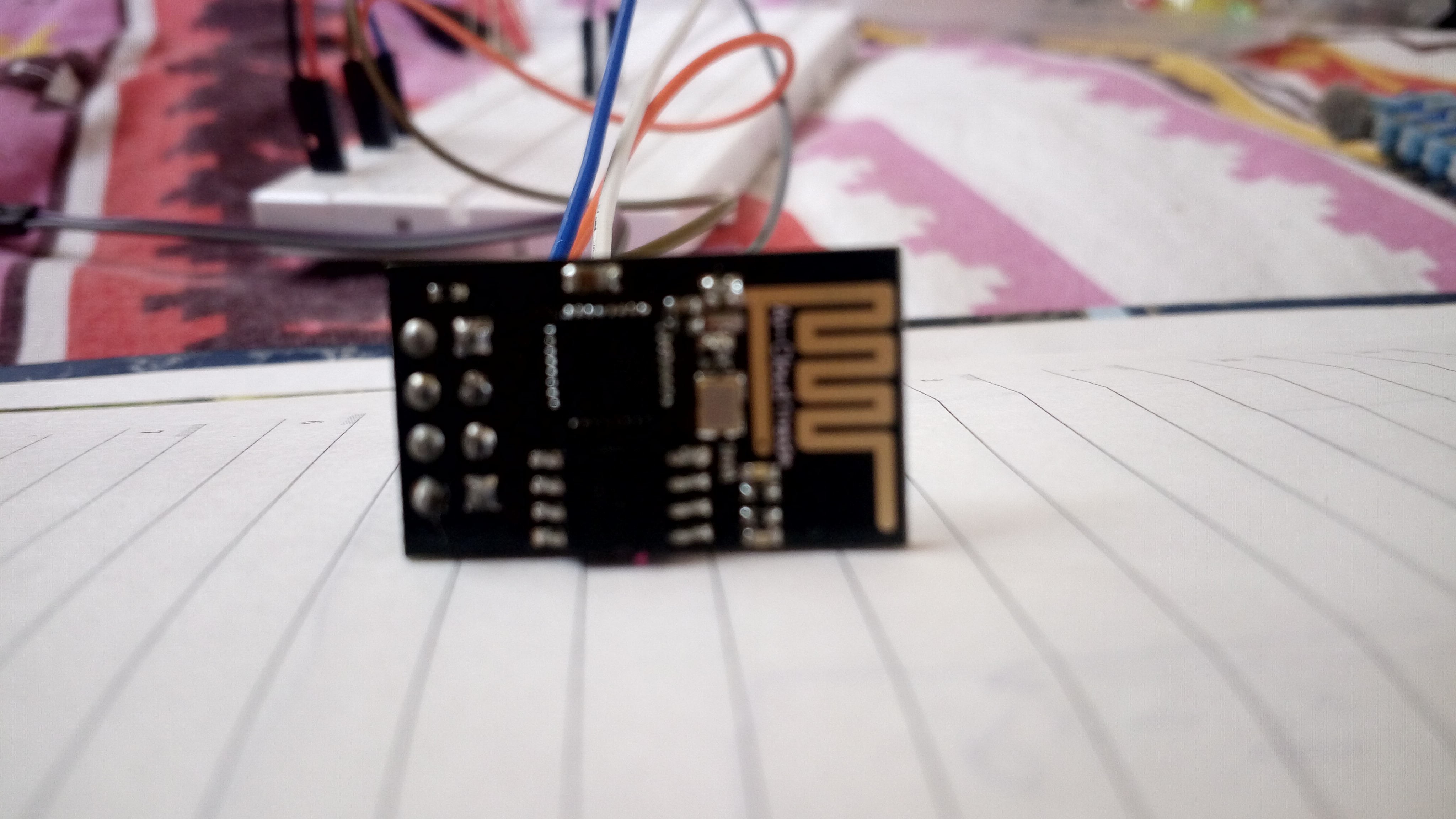
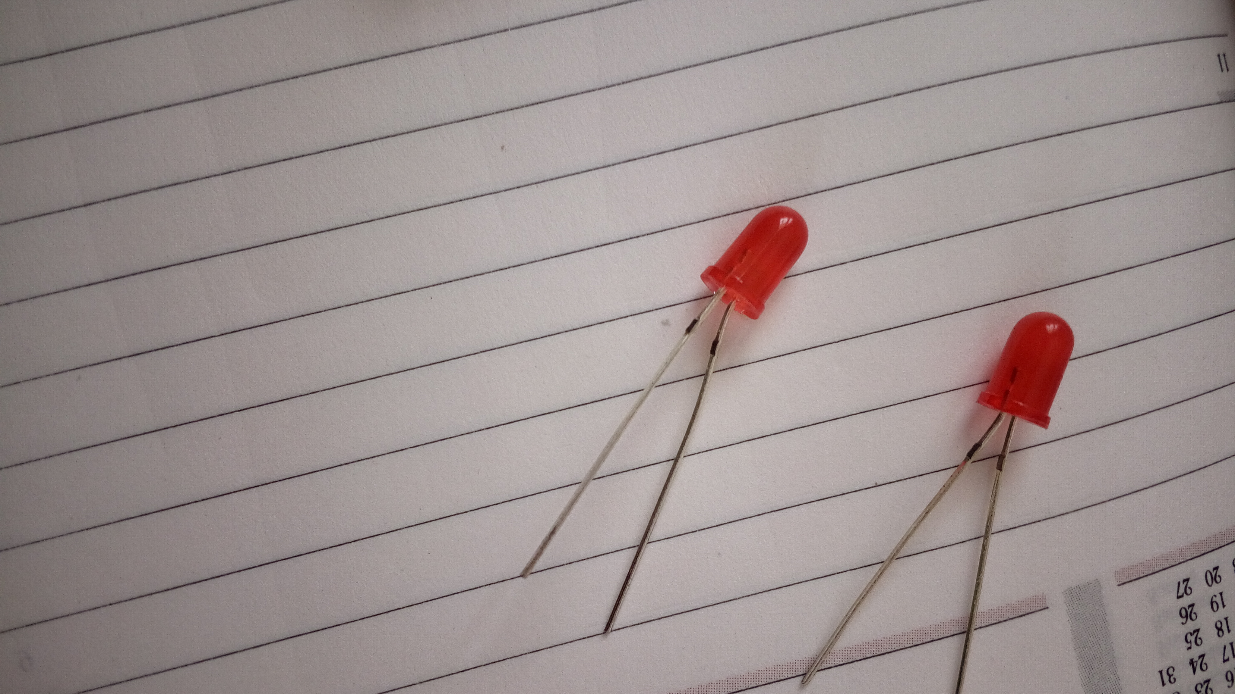
I had huge difficulty when I started using and understanding ESP8266 01, so thought making this tutorial could help Newbies in their first use... This is as simple as it can be.
Items
so as this is very basic tutorial the minimum items required are:
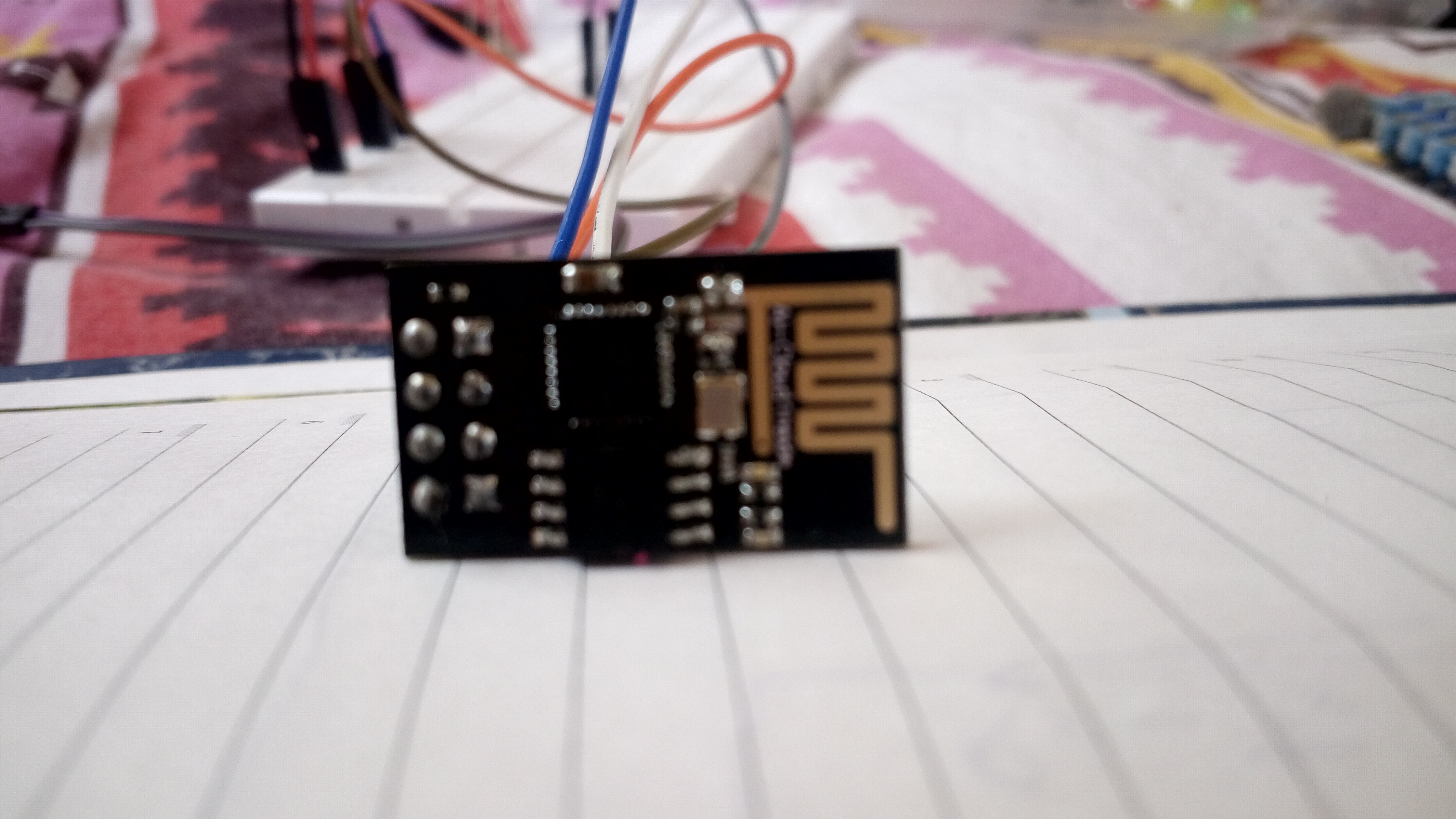
1. ESP8266-01
2. FTDI module
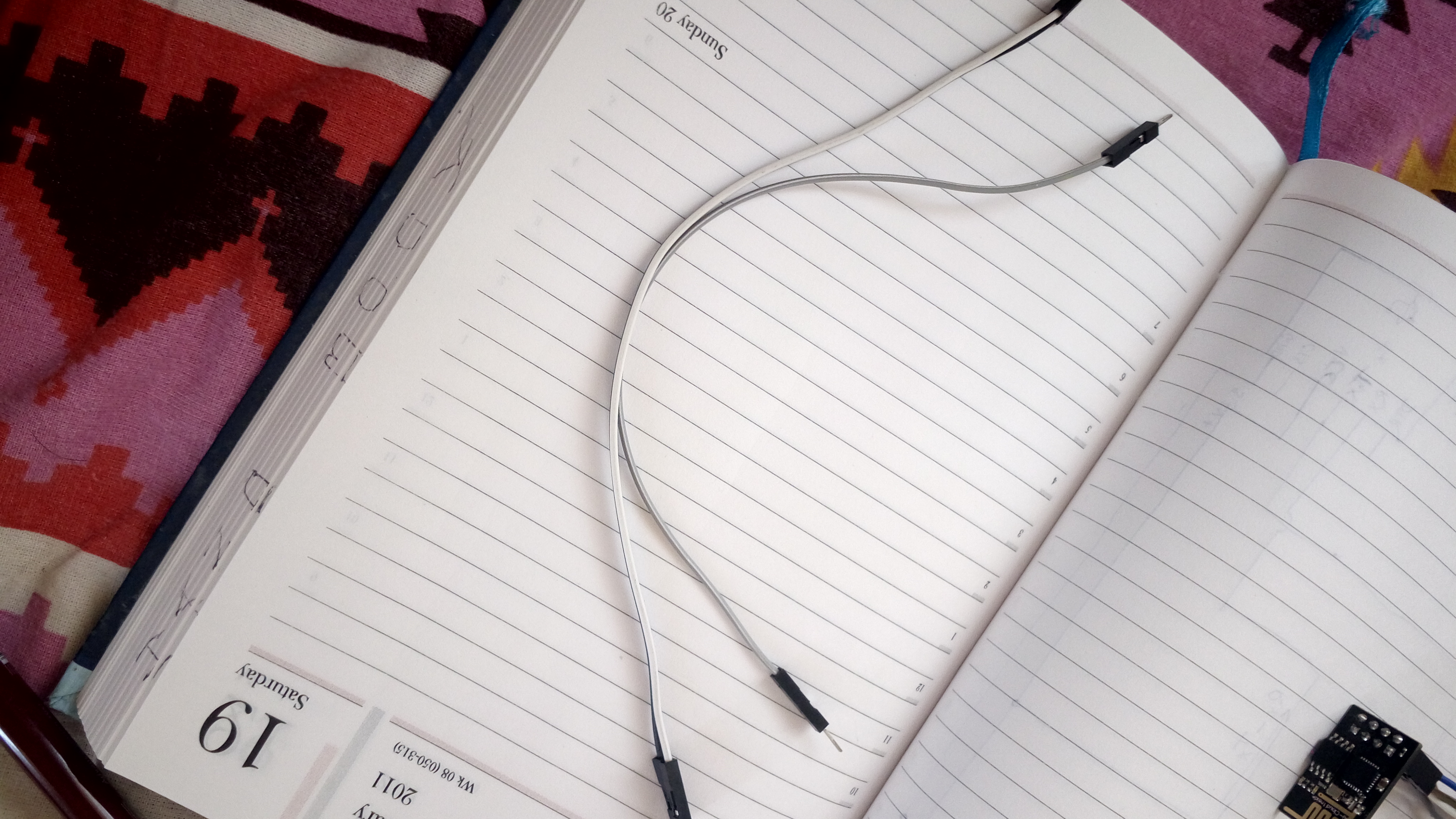
3. Jumper cables (9) to be precise 2 nos F-F, 7nos Male - female.
4. Bread board
5. a Computer to upload program
6. Android / ios mobile to control your project
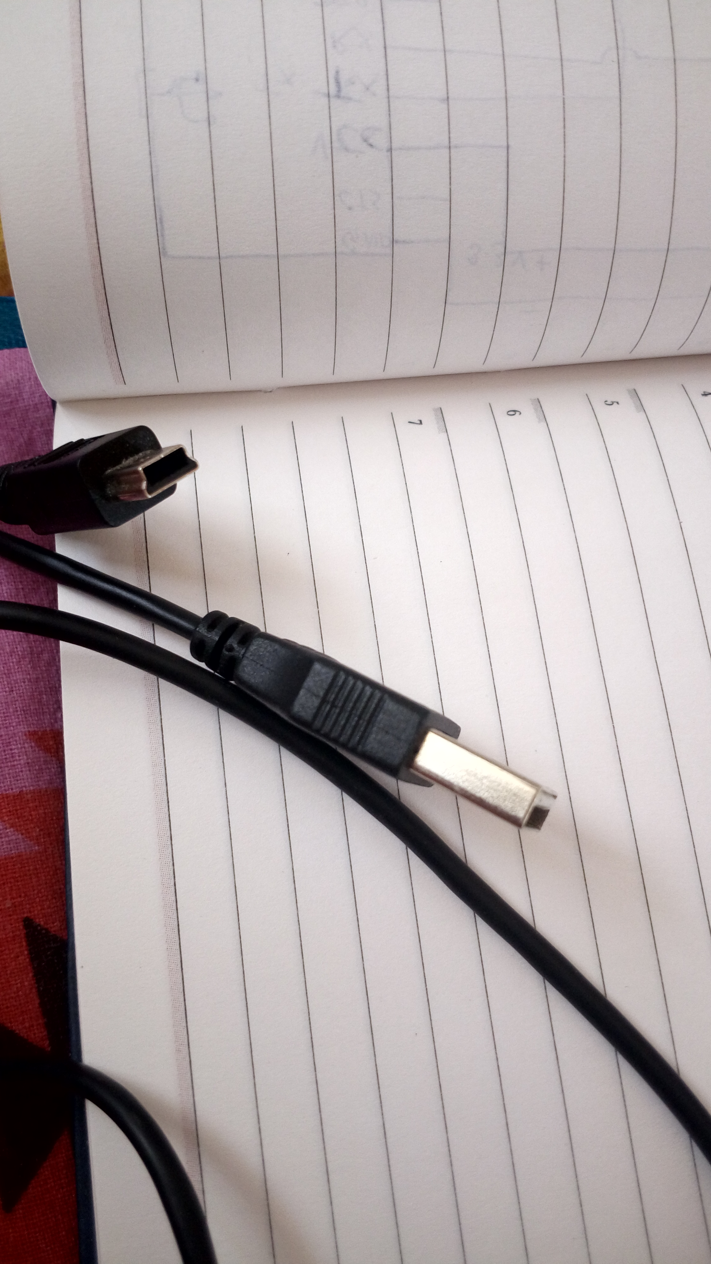
7.USB cable to connect FTDI to computer.
1. ESP8266-01
2. FTDI module
3. Jumper cables (9) to be precise 2 nos F-F, 7nos Male - female.
4. Bread board
5. a Computer to upload program
6. Android / ios mobile to control your project
7.USB cable to connect FTDI to computer.
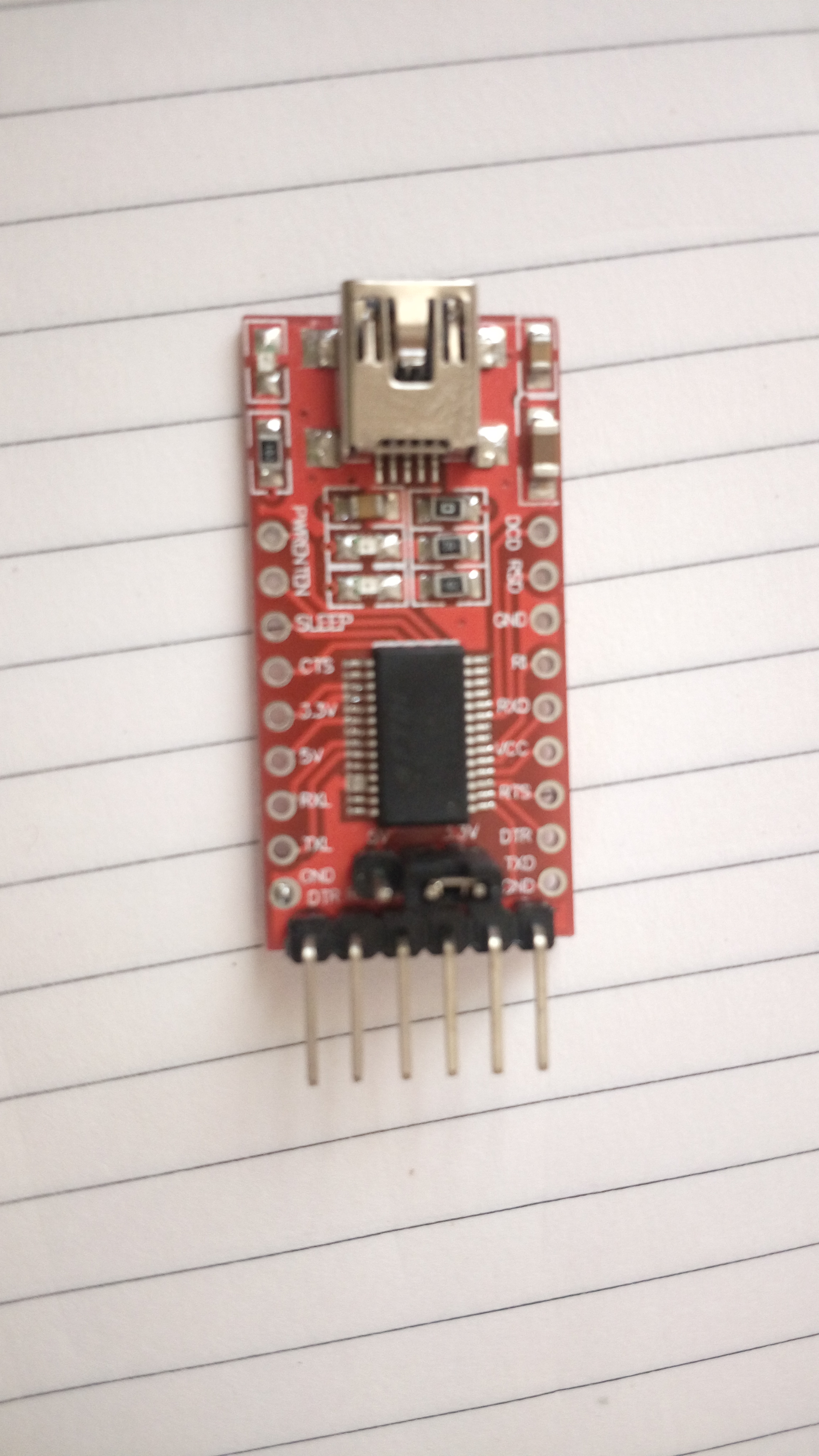
The FTDI
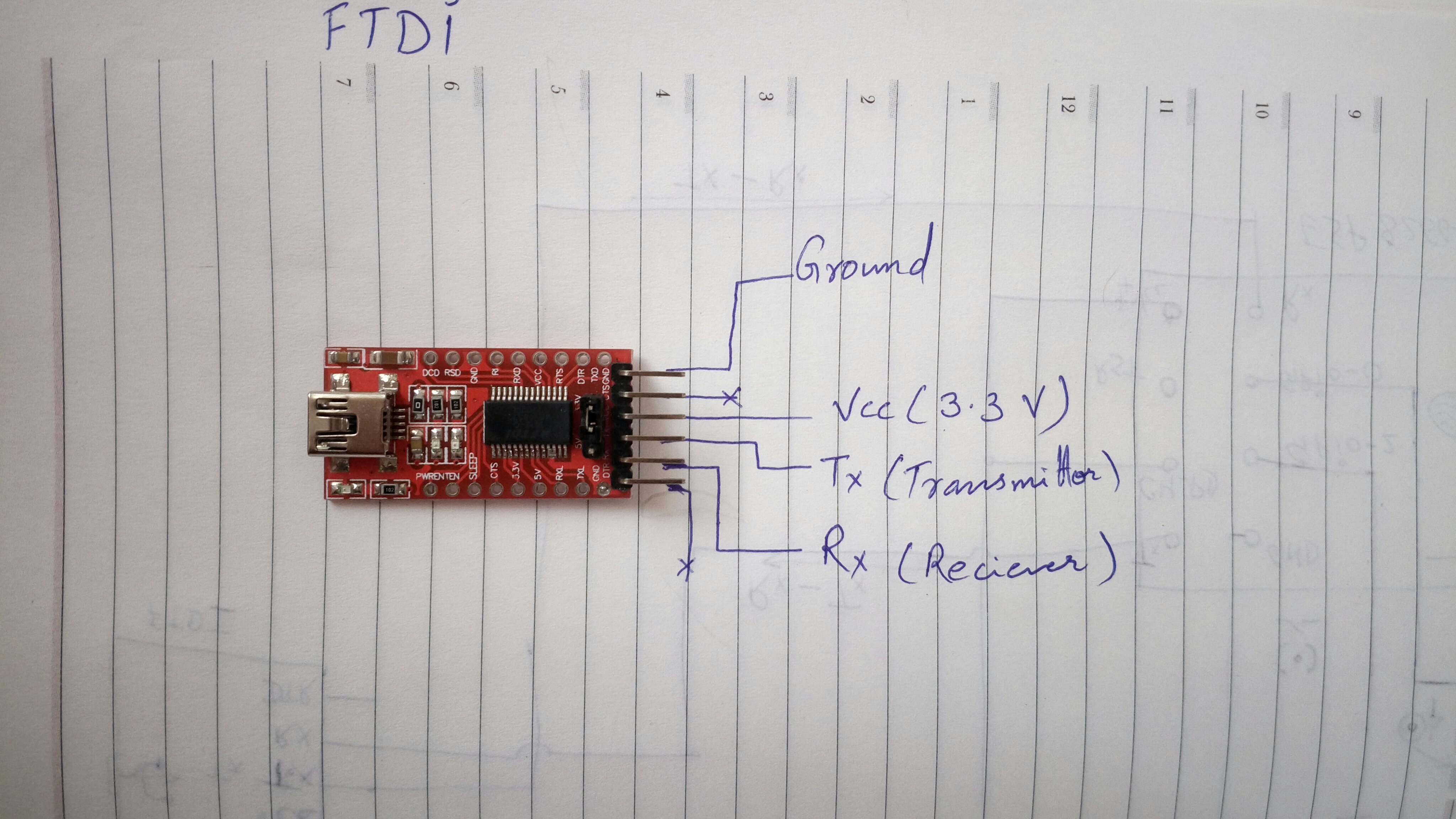
out of the 6 pins of the FTDI we use only 4
1. Ground
2. Don't use ❌
3. Vcc (+ve) set it to 3.3V always, higher voltage can damage your ESP
4. Tx - The transmitter
5. Rx - The Receiver pin
6. Don't use ❌
1. Ground
2. Don't use ❌
3. Vcc (+ve) set it to 3.3V always, higher voltage can damage your ESP
4. Tx - The transmitter
5. Rx - The Receiver pin
6. Don't use ❌
The ESP and Pins
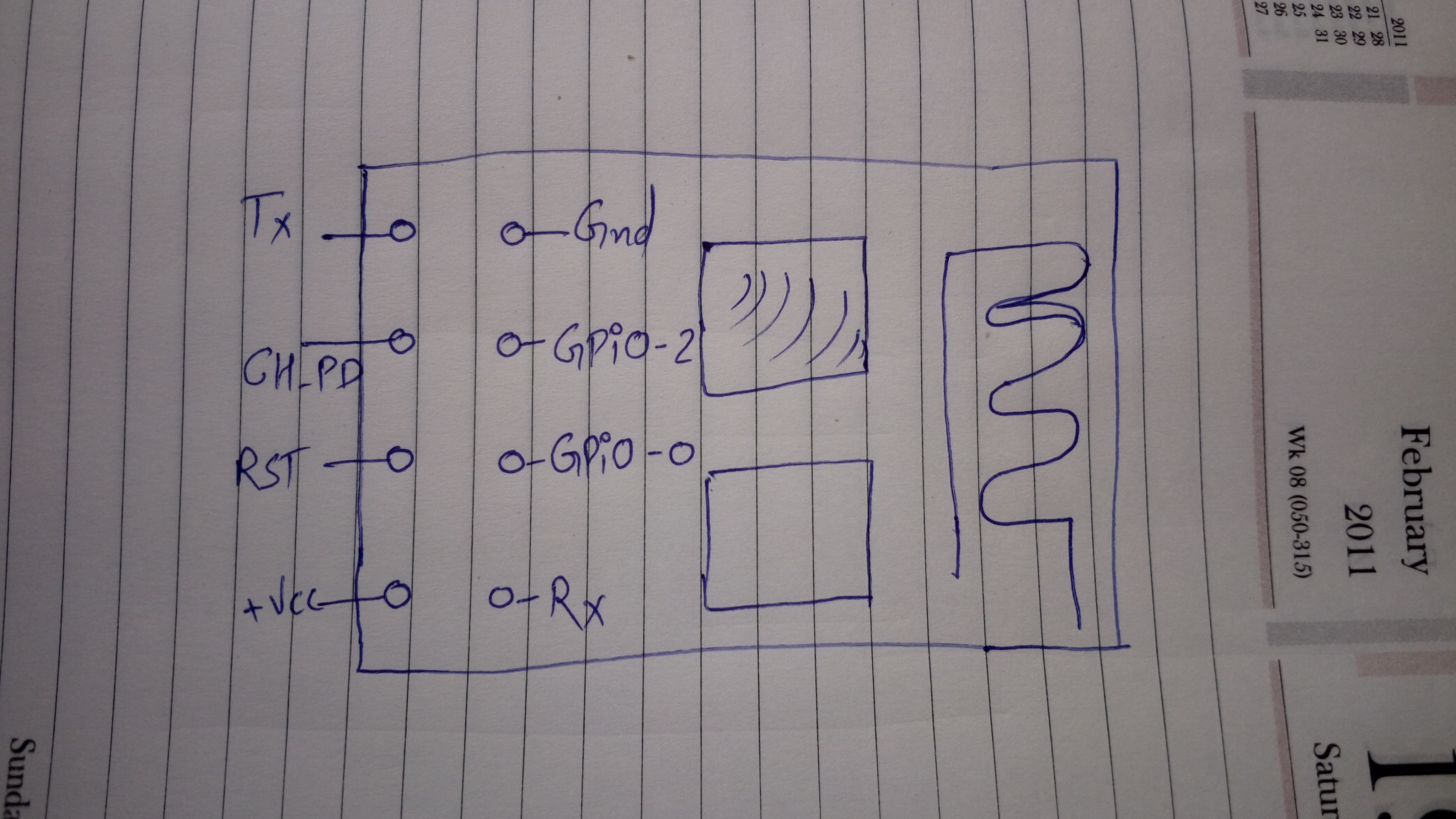
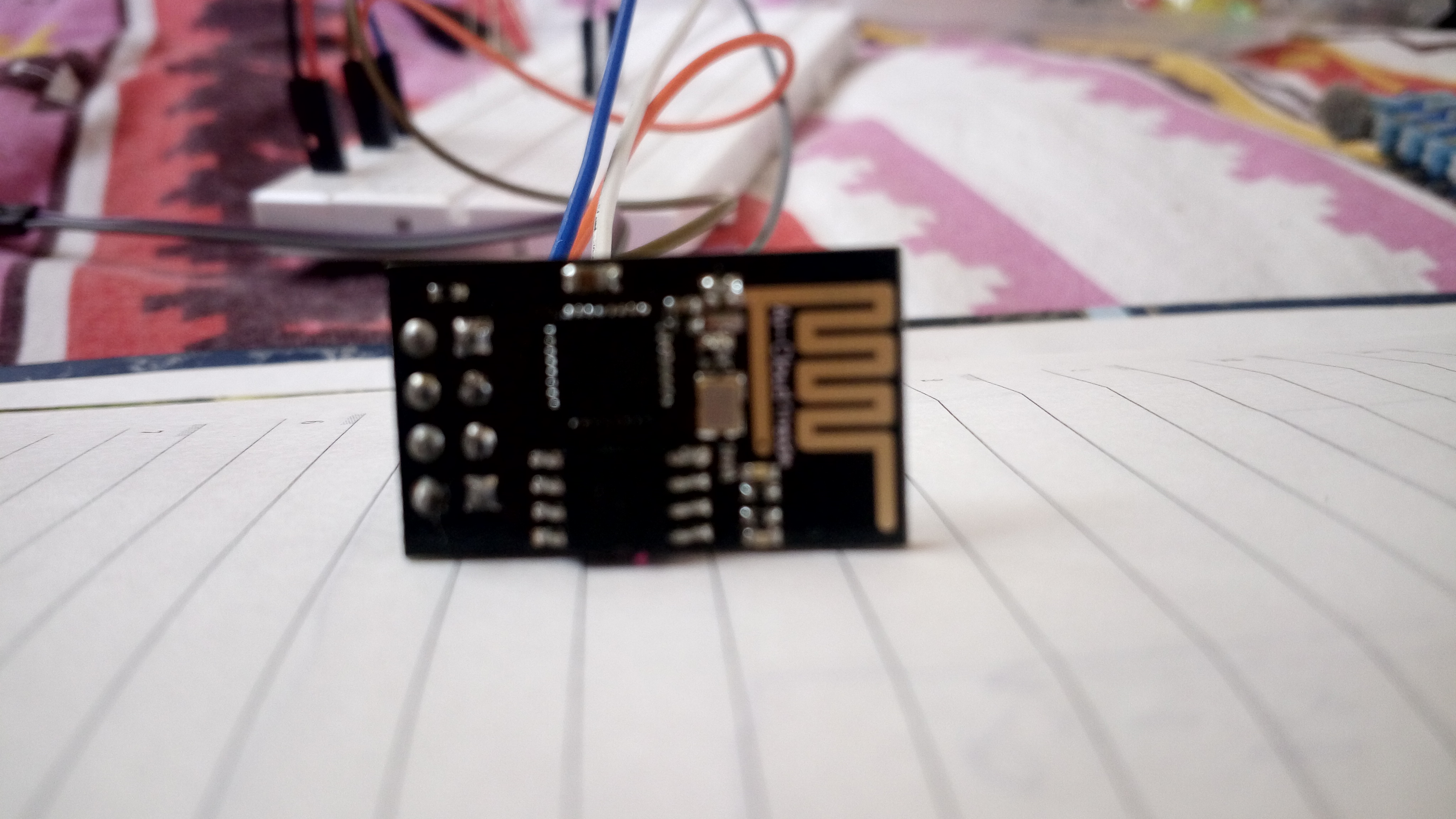
so basically of the 8 pins of the ESP,
1. Tx Transmission pin
2. Ch_PD Chip enable pin
3. RST Reset pin
4. Vcc +ve pin
5. Gnd Ground Pin
6. GPio 2 - Input output pin 2
7. GPio 0 - Input output pin 0
8. Rx - Receiver pin
1. Tx Transmission pin
2. Ch_PD Chip enable pin
3. RST Reset pin
4. Vcc +ve pin
5. Gnd Ground Pin
6. GPio 2 - Input output pin 2
7. GPio 0 - Input output pin 0
8. Rx - Receiver pin
Connection and Points to Be Remembered
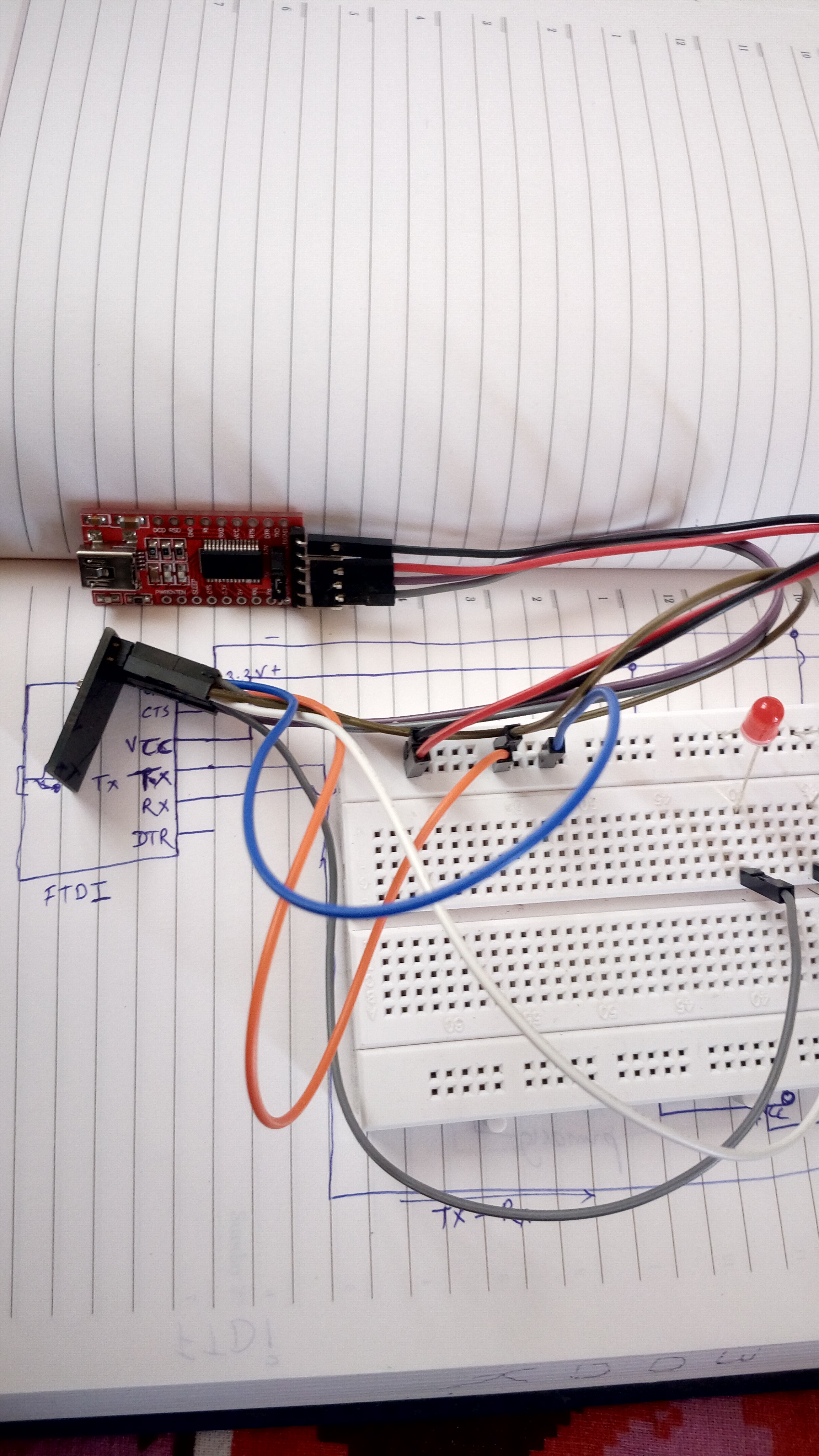
1. Vcc is always 3.3 v
2. Transmission pin- Tx of FTDI is always connected to Receiver pin - Rx of the ESP and vice versa.
3. Vcc and CH_ PD of ESP is always connected to Vcc 3.3 v of FTDI
4. Ground to ground.
2. Transmission pin- Tx of FTDI is always connected to Receiver pin - Rx of the ESP and vice versa.
3. Vcc and CH_ PD of ESP is always connected to Vcc 3.3 v of FTDI
4. Ground to ground.
Setting Up Blynk App
Download Blynk app from Android Play store
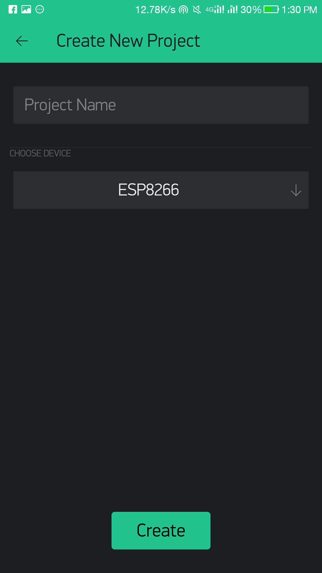
Open, Sign up for new user with your email, Create new Project, Give project name, select Device to ESP8266, connection type Wi-Fi and create..
once create is pressed You will be sent Token
Open, Sign up for new user with your email, Create new Project, Give project name, select Device to ESP8266, connection type Wi-Fi and create..
once create is pressed You will be sent Token
ESP and Blynk- Connection, Setup and Programming
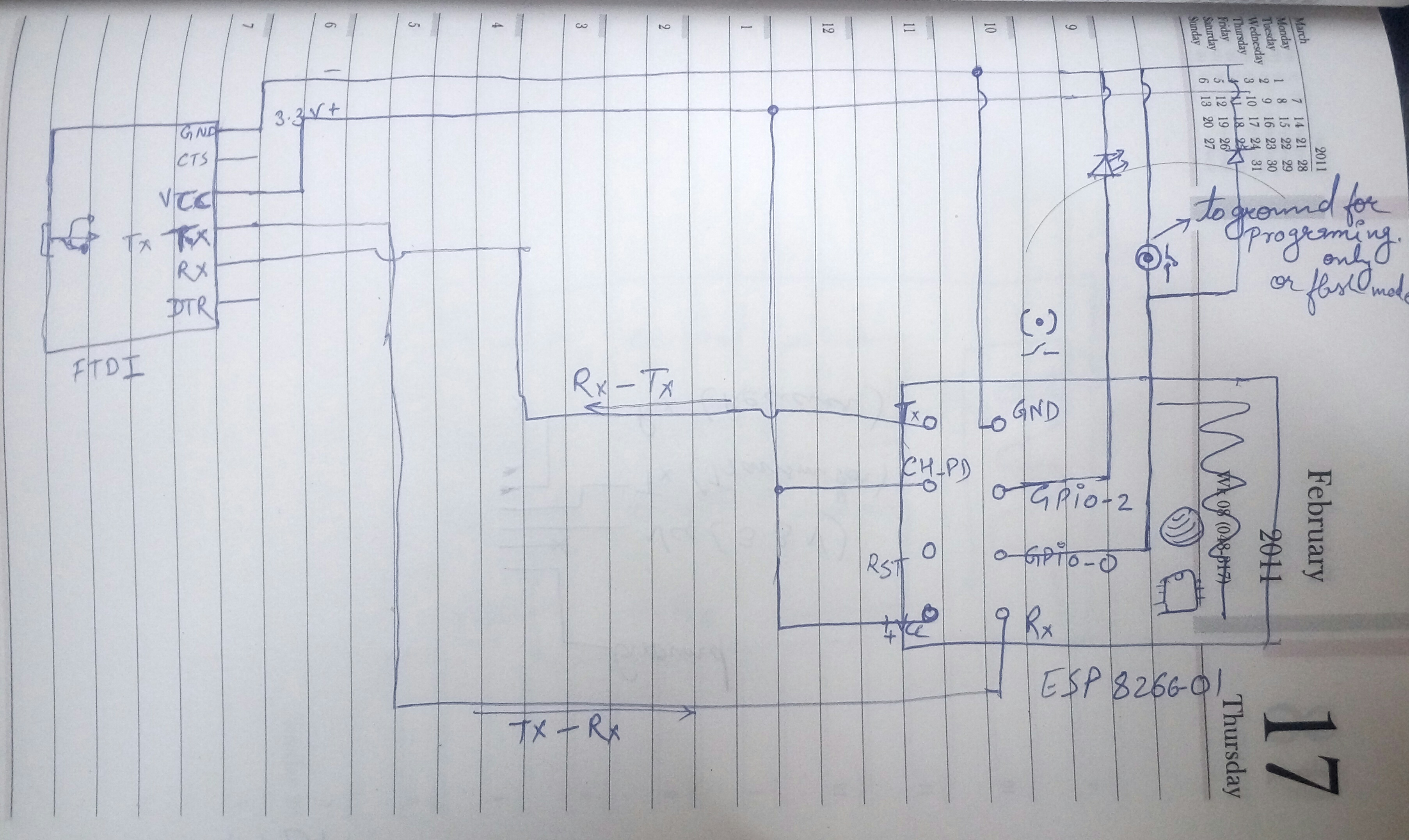
Now as Blynk is almost setup, we connect the FTDI to computer via USB cable and GPio 0 pin of the ESP to ground which enables programming or flash mode. once this is done follow the bellow steps :
1. Open Arduino IDE if u don't have one download it from www.Arduino.cc
a.open new project
b.select board as Generic ESP8266 module
c.open examples > Blynk > boards_wifi > Esp8266_Standalone
****imp: if you don't have board option for ESP 8266, Blynk library in examples refer to my other tutorial on them,
2. once above is done Change the AuthToken with authentication token received on your email
3. Change ssid n pass to your wifi network Name and password, if u don't have u can use your mobiles hotspot too.
4. Once done hit verify, it shouldn't give any error if all steps are followed properly
5. hit upload. once the upload is complete and successful, "disconnect" the GPIO 0 pin from the ground. plug the pin to other pin of bread board as it can be used to control 1 LED.
once done good to go...
The Control
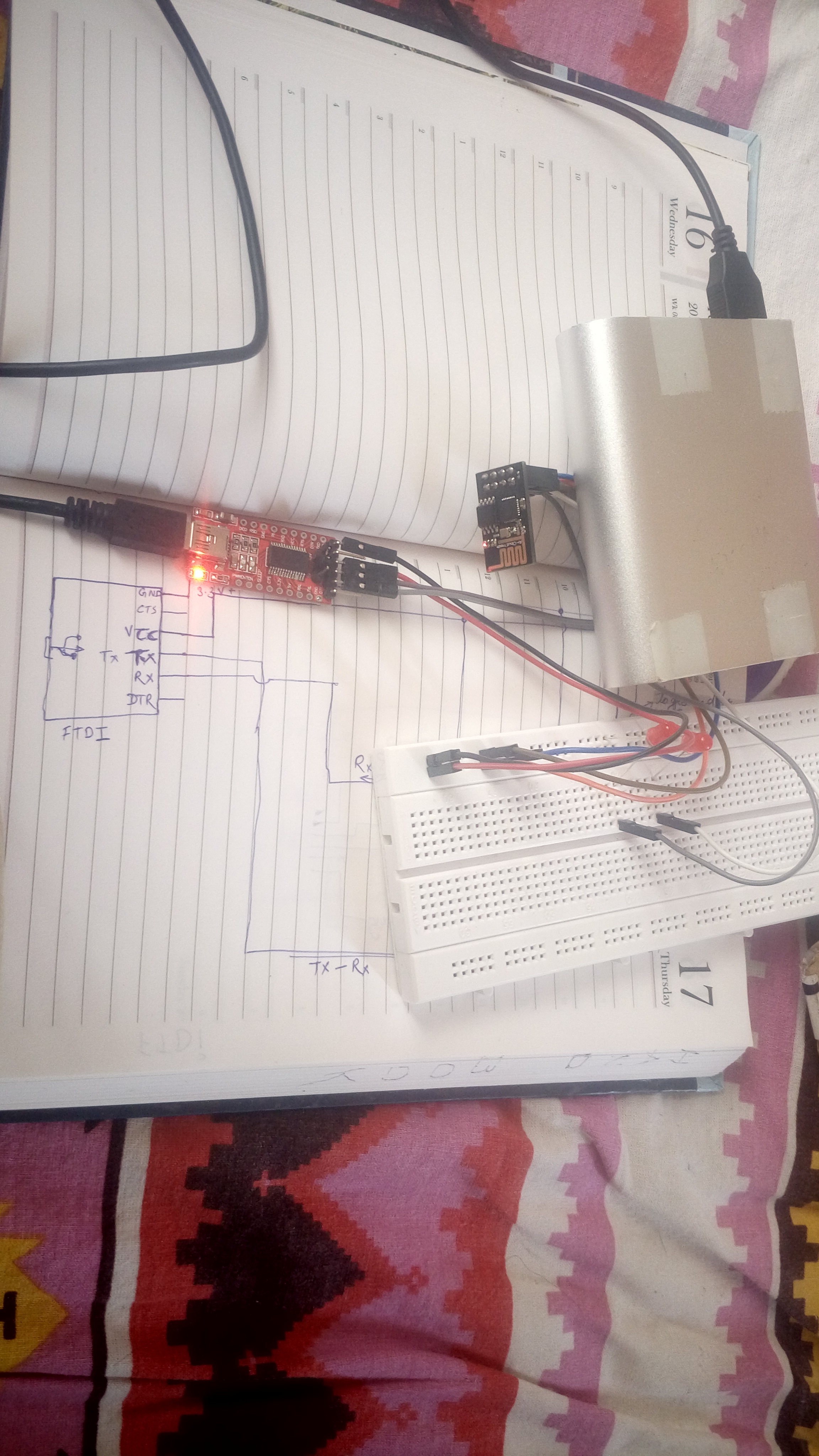
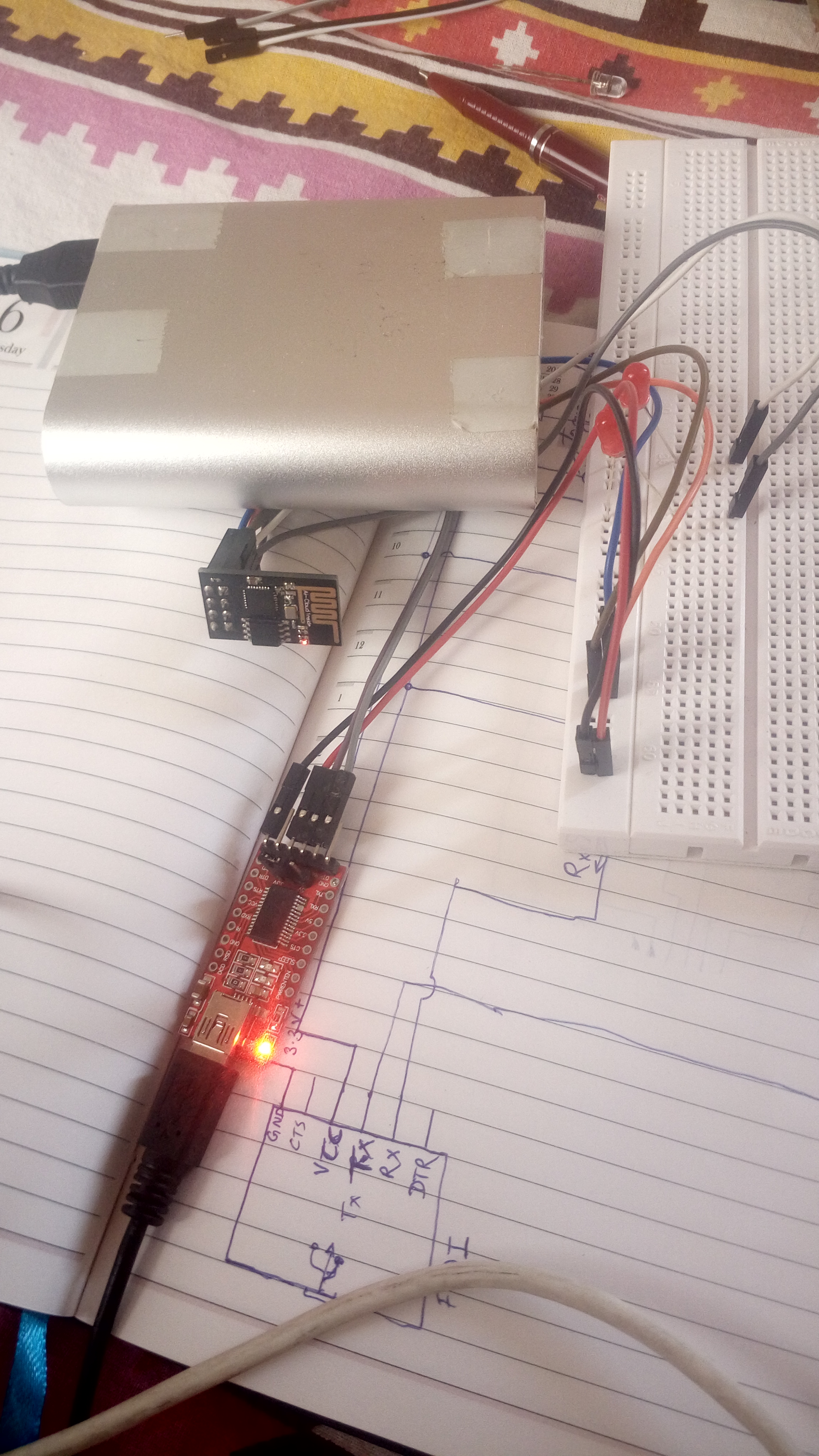
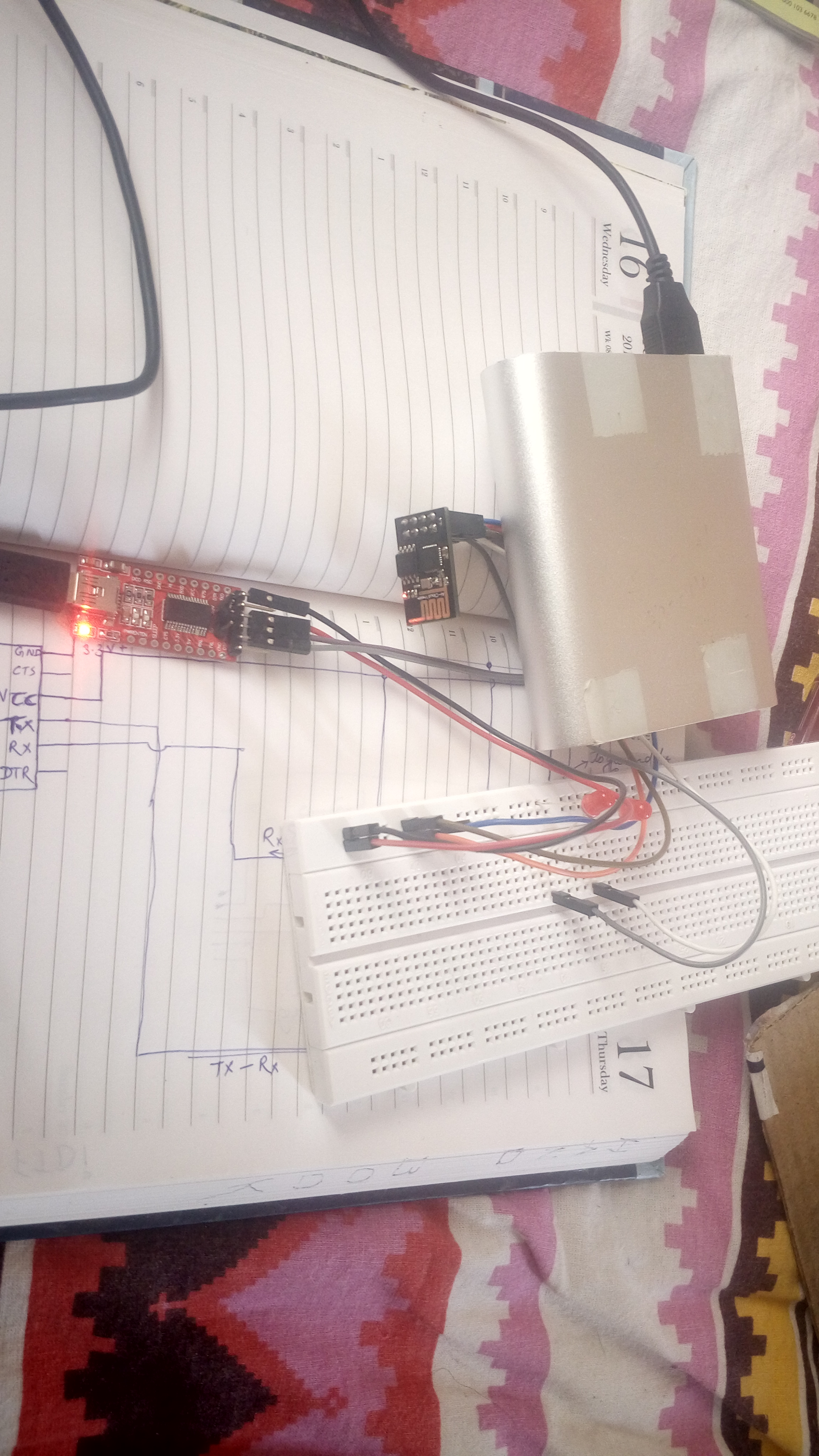
As Uploading is done you can disconnect the USB cable from your computer, can be powered from a power bank too..
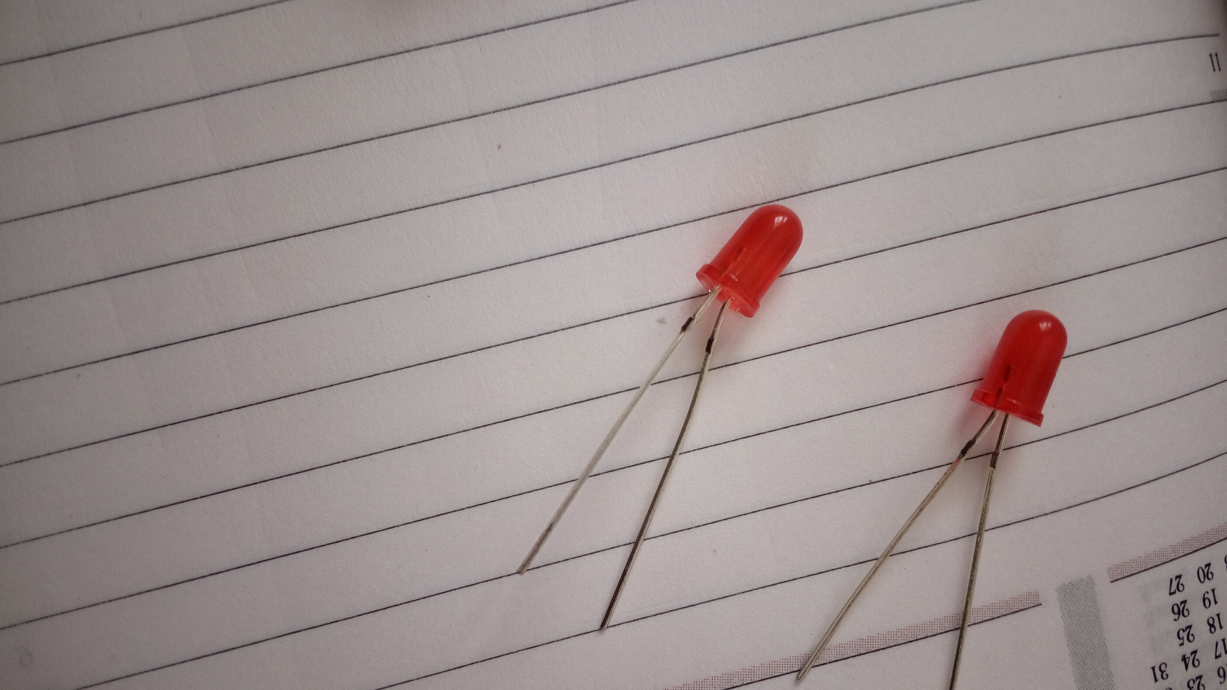
** Insert LED between ground and GPIO pins each .which you want to control.
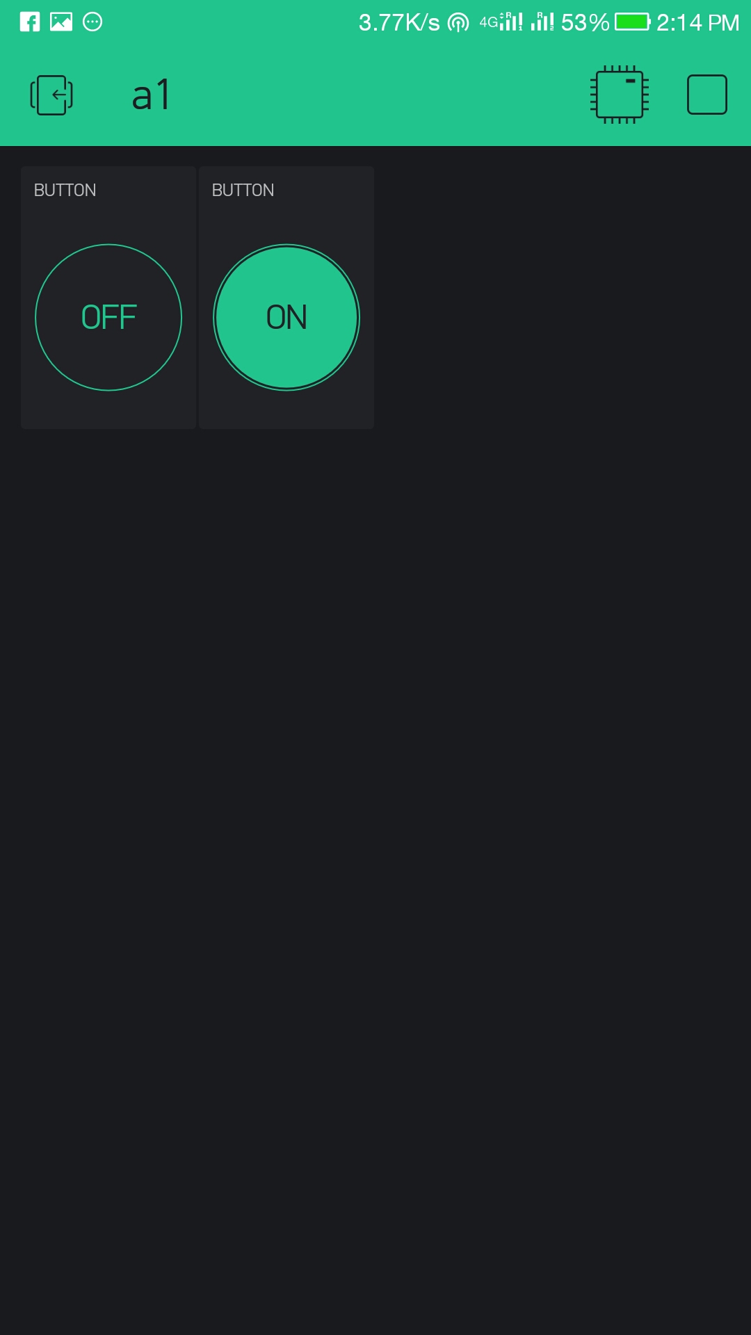
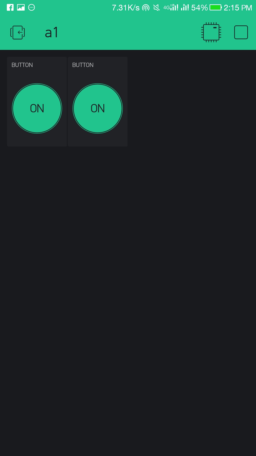
1. open Blynk app, you will see your project openand it
2. add 2 buttons to your project
3. click on the buttons and select pins to Digital Gp0 and Gp2 respective for the 2 buttons.
4. Select if you want a push or button switch
5. once done press the play button next to add
a. if the device is not connected to internet it will show "device not connected" or "device offline".
b. if device is connected you can see info of device by pressing button next to stop.
6. Once done you are ready to rock the LEDs from your mobile.
Hurrah!!!!!!
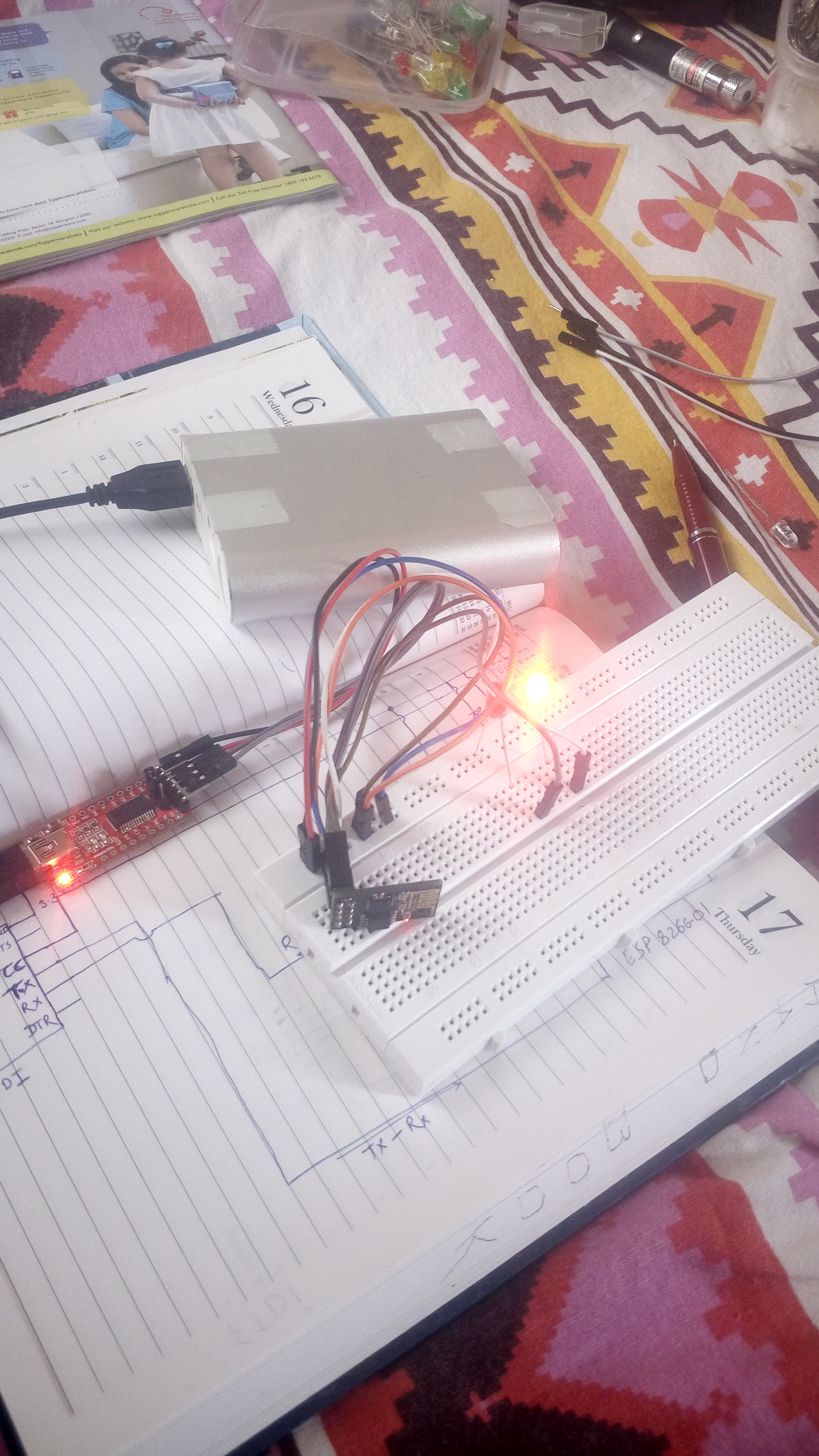
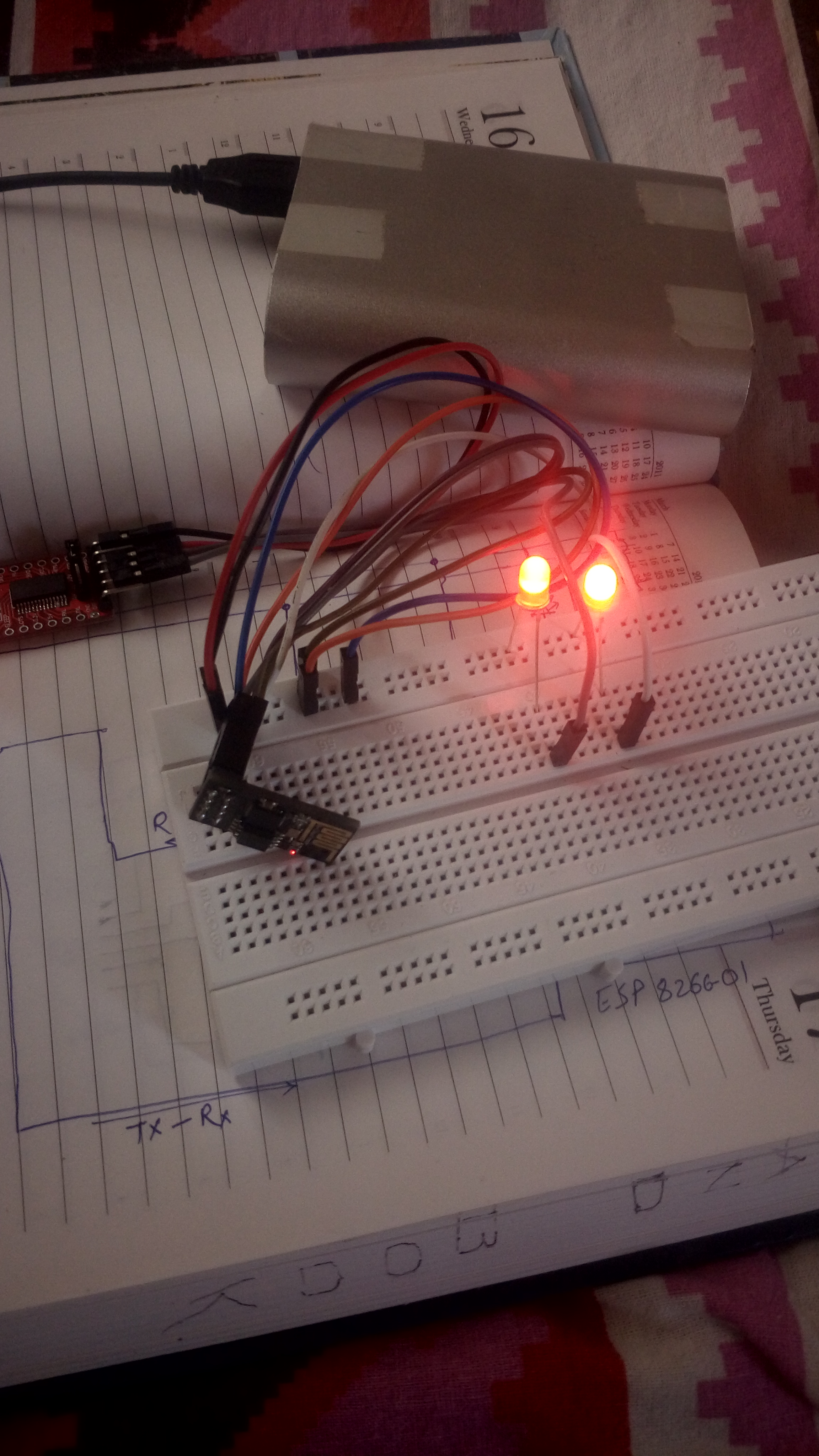
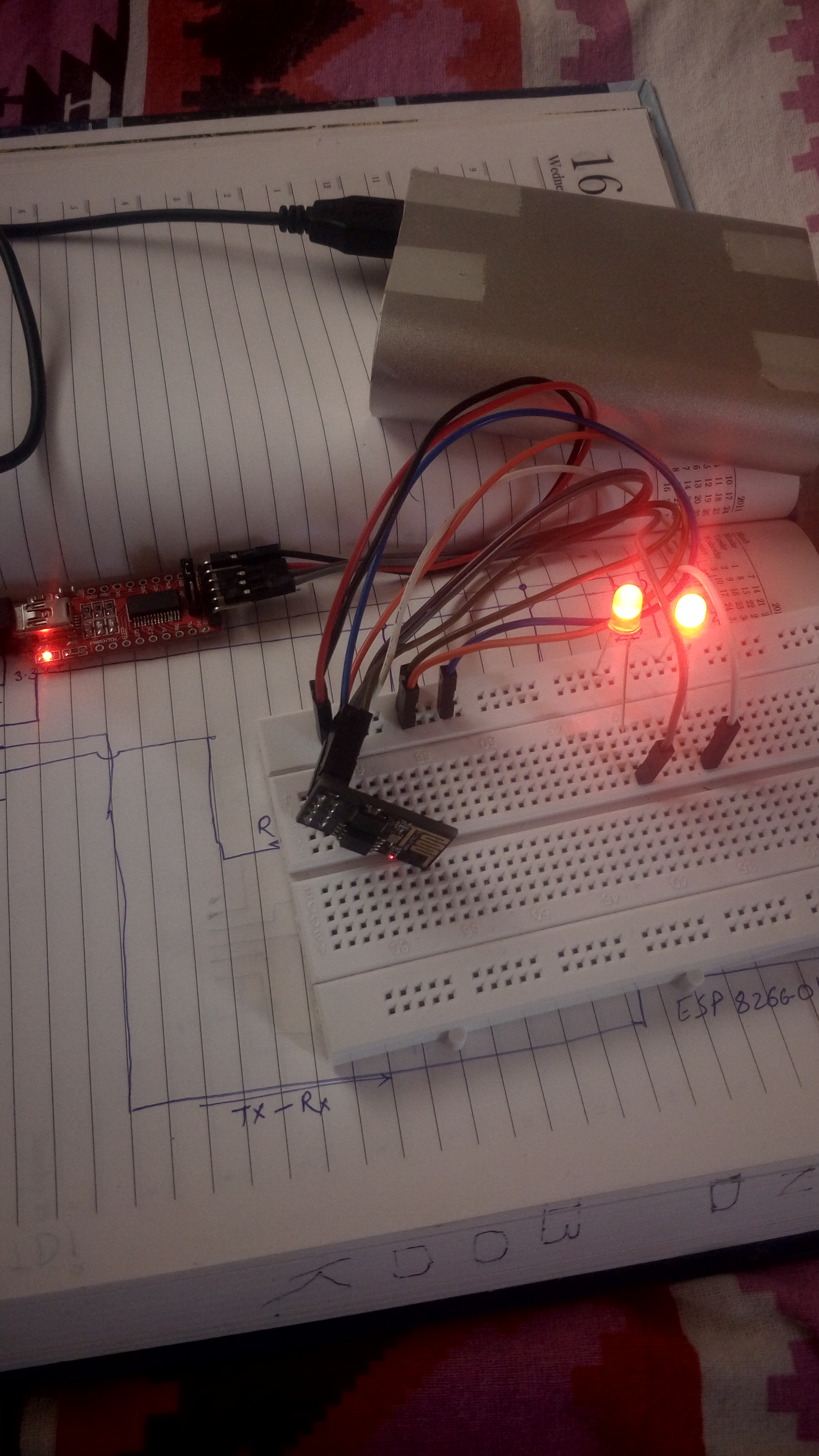
You just made the LEDs glow on the press of your fingers... Rock the LEDs and ESP8266... Hurrah...!!! it's party time ...