ESP32 Handheld Game Console
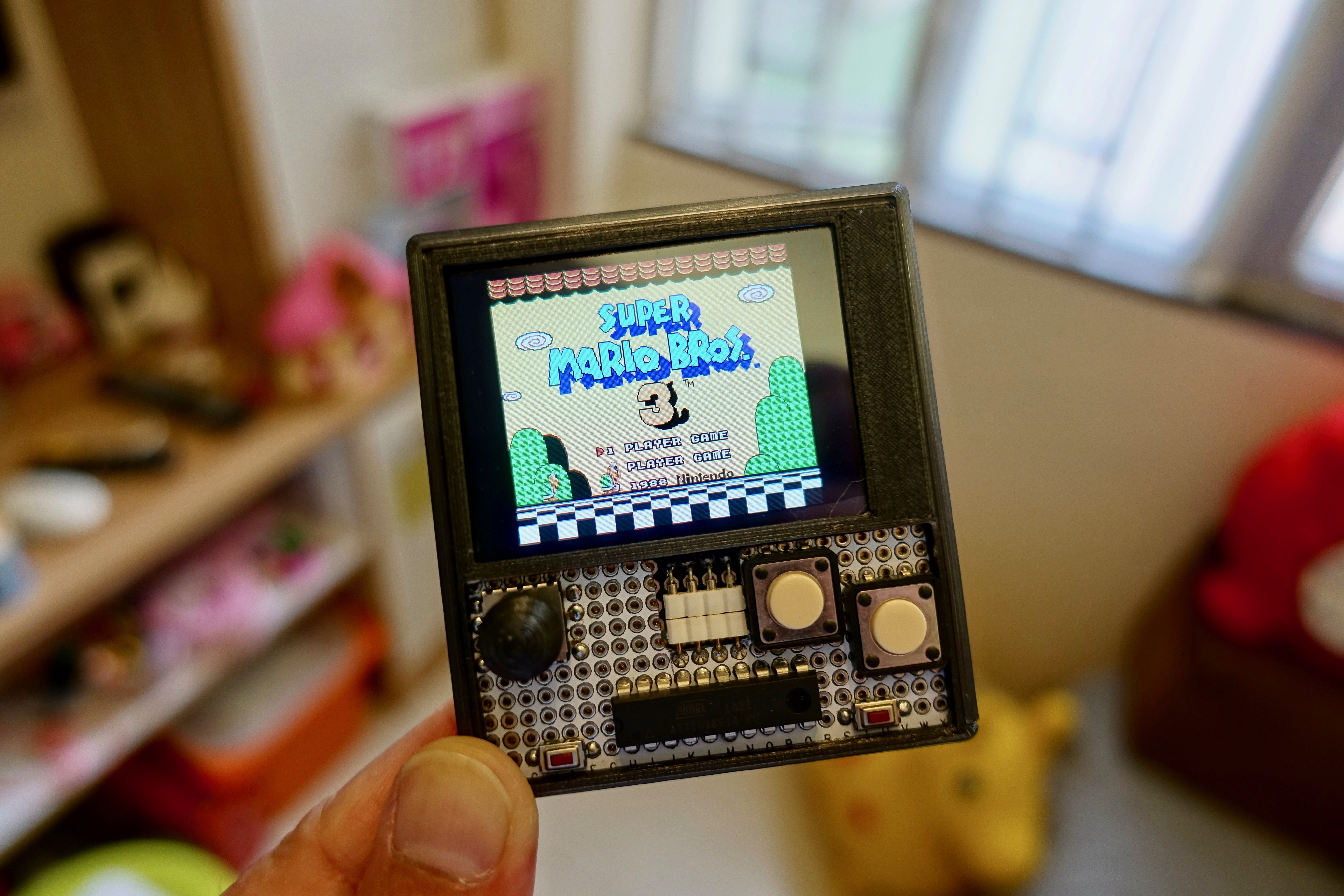
This instructables show how to use a ESP32 and ATtiny861 to build a NES emulator game console.
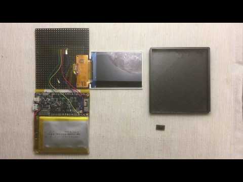
Hardware Preparation
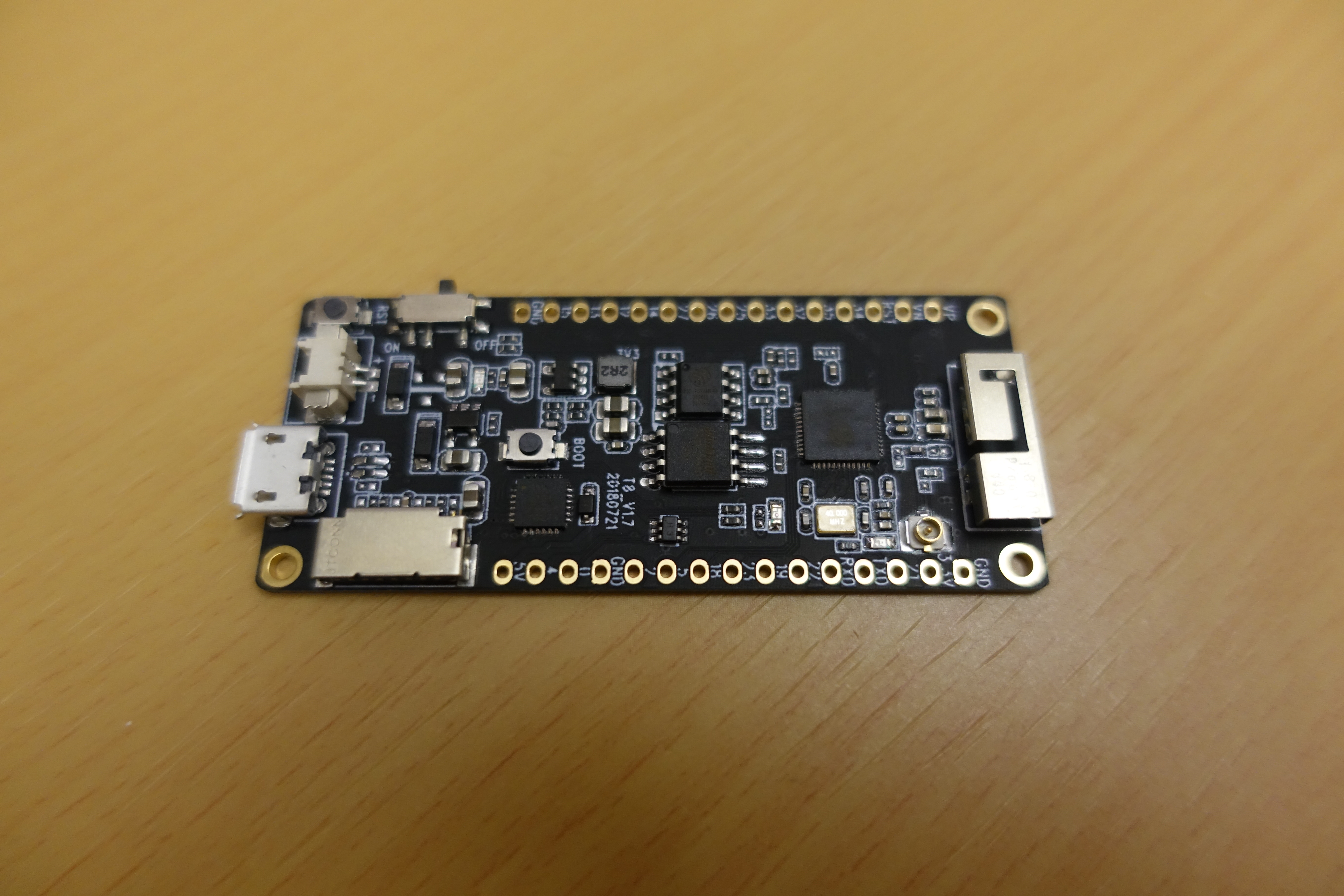
ESP32 Dev Board
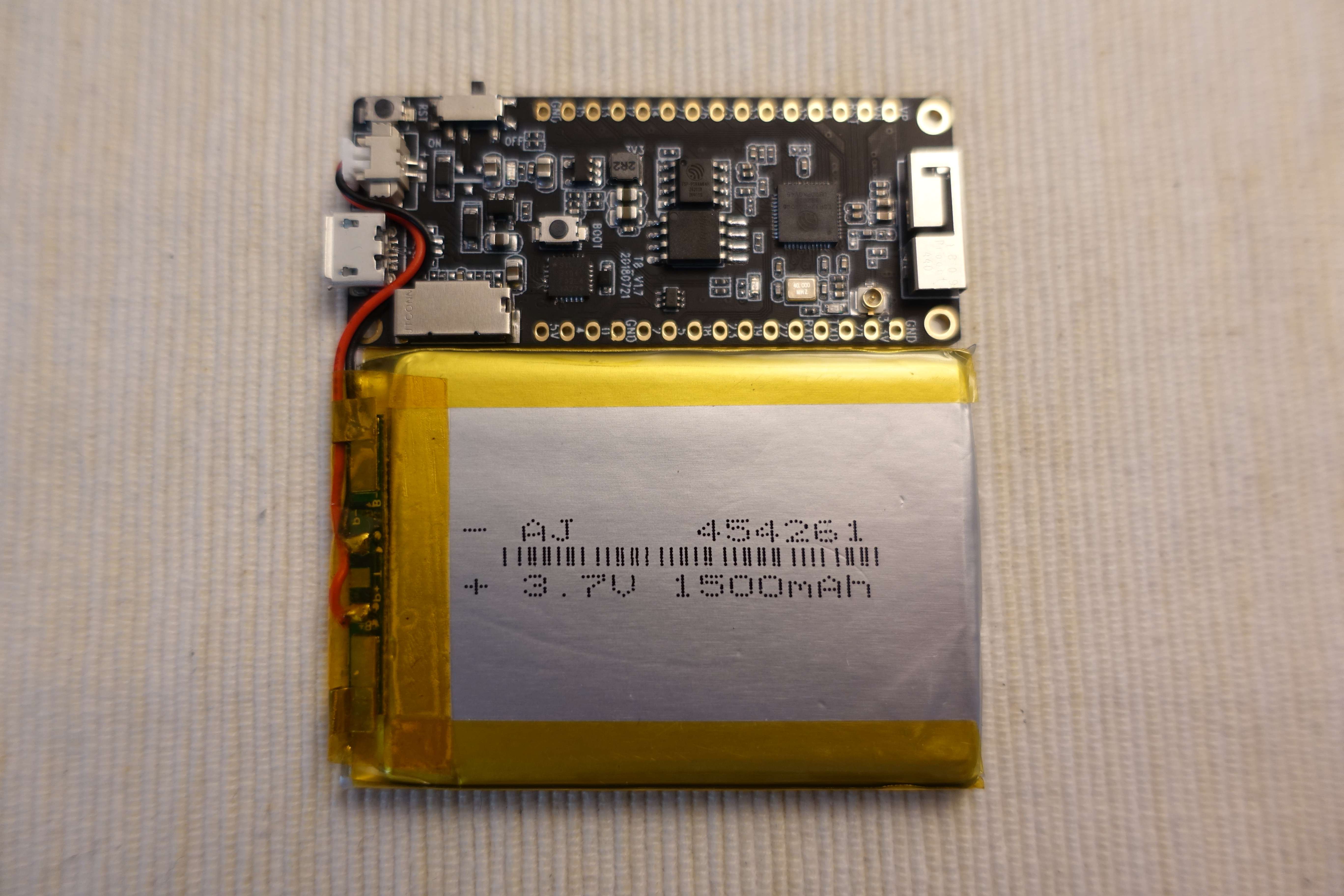
This time I am using a TTGO T8 ESP32 dev board. This board have built-in Lipo charging and regulating circuit, it can help reduce the extra components.
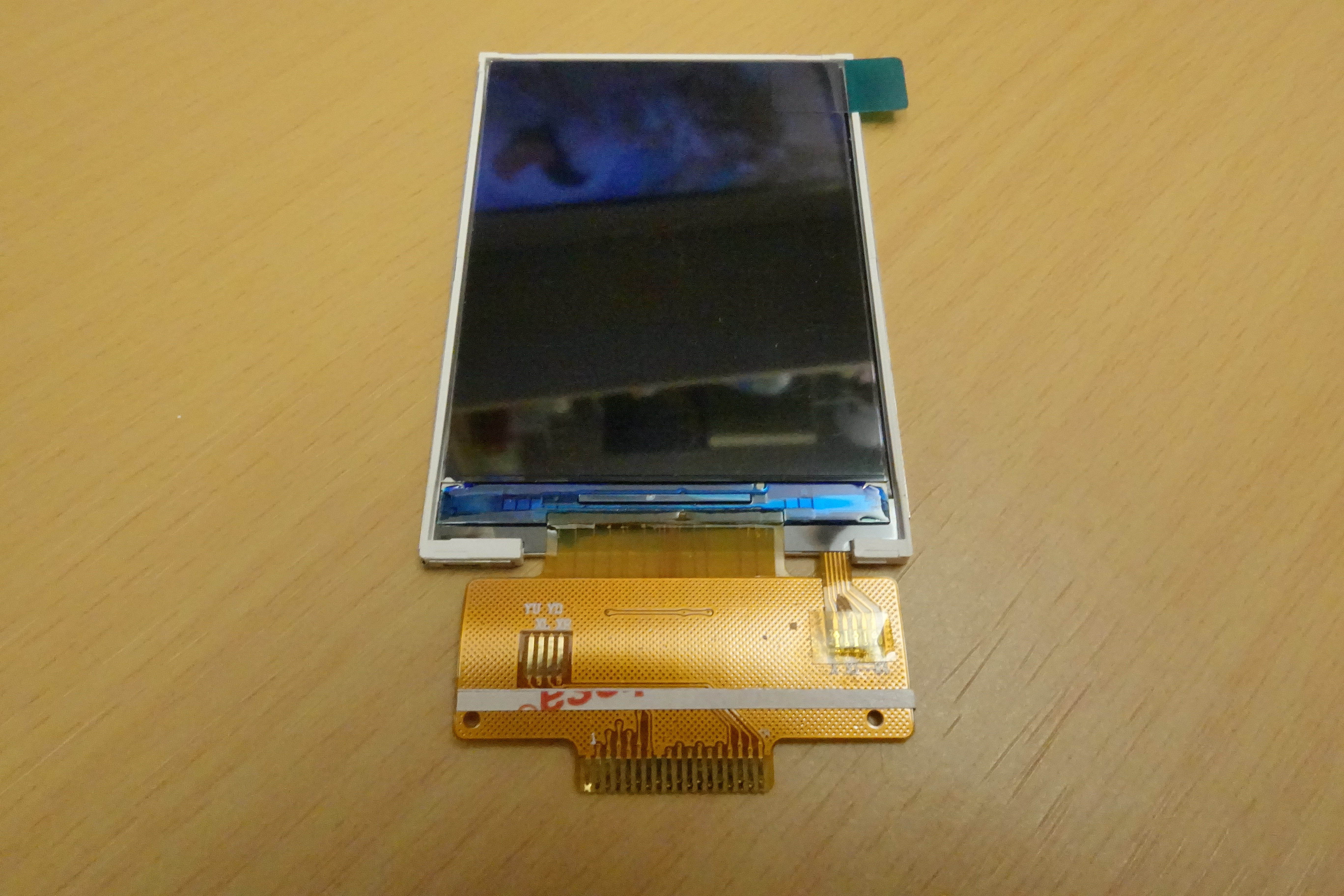
Display
This time I am using a 2.4" IPS LCD. The driver controller is ST7789V and the resolution is 320 x 240. This resolution is best fit for NES emulator 252 x 224 resolution.
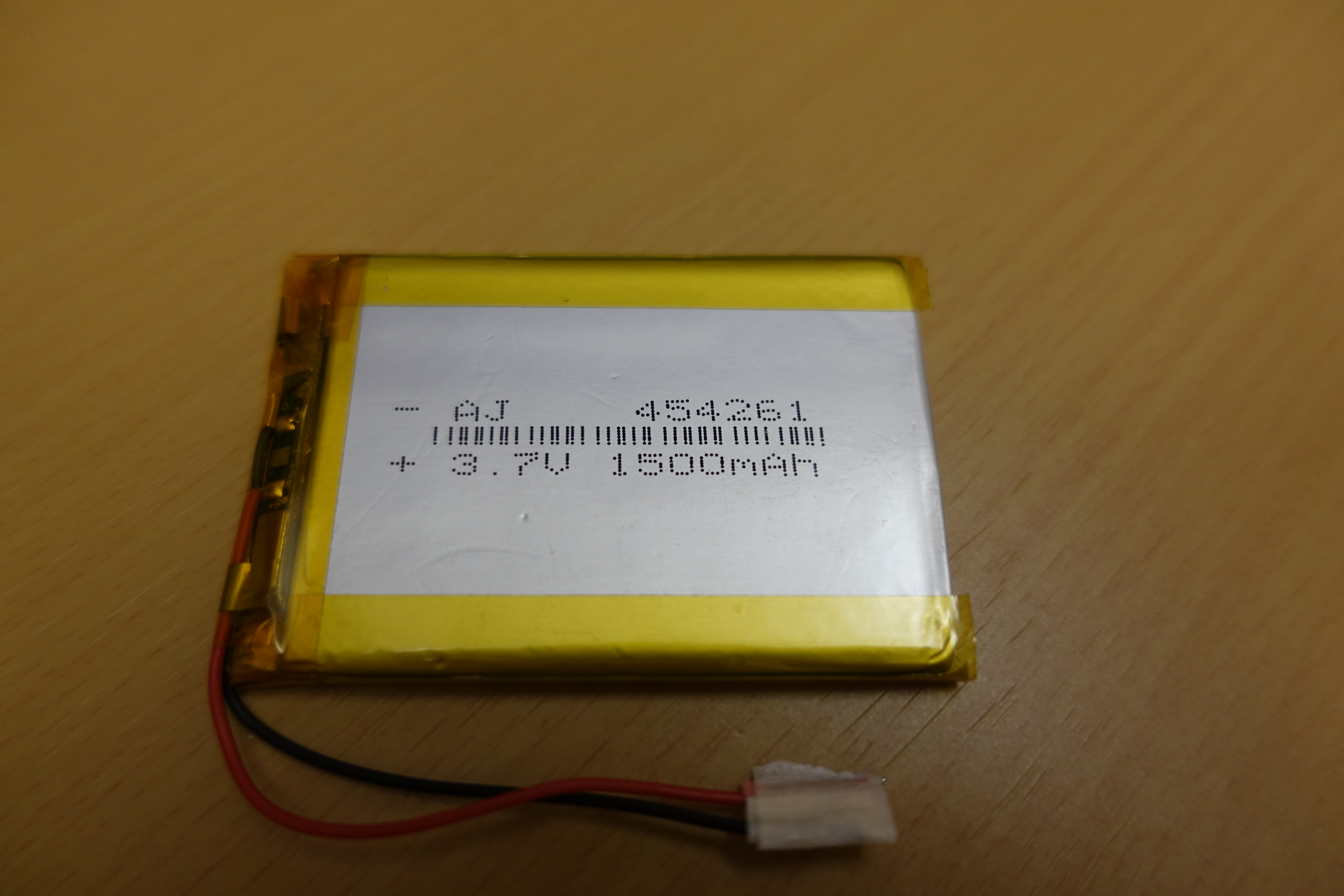
Battery
This time I am using a 454261 Lipo battery. 4.5 mm is the thickness of ESP32 dev board, and 61 mm is the width of the board.
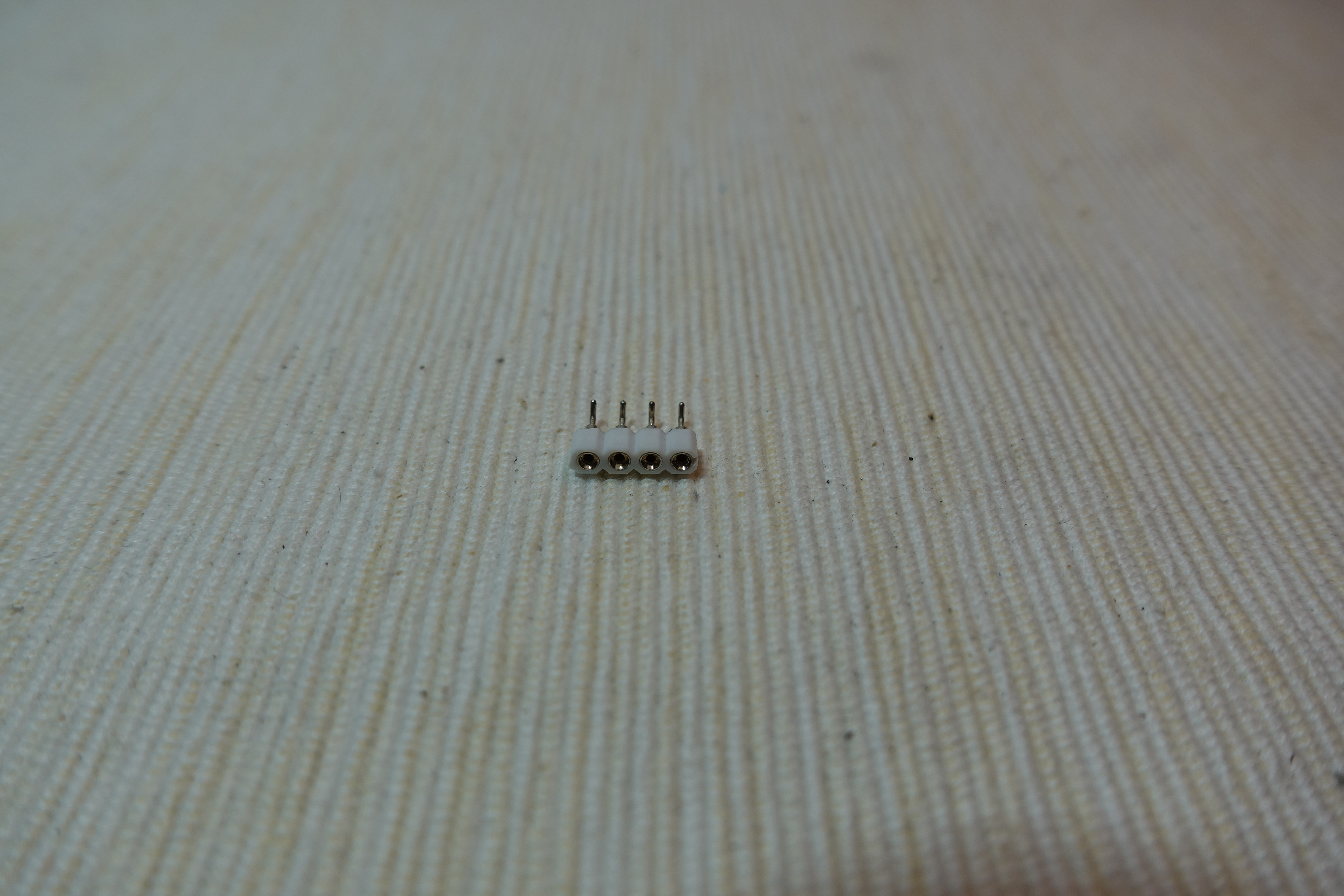
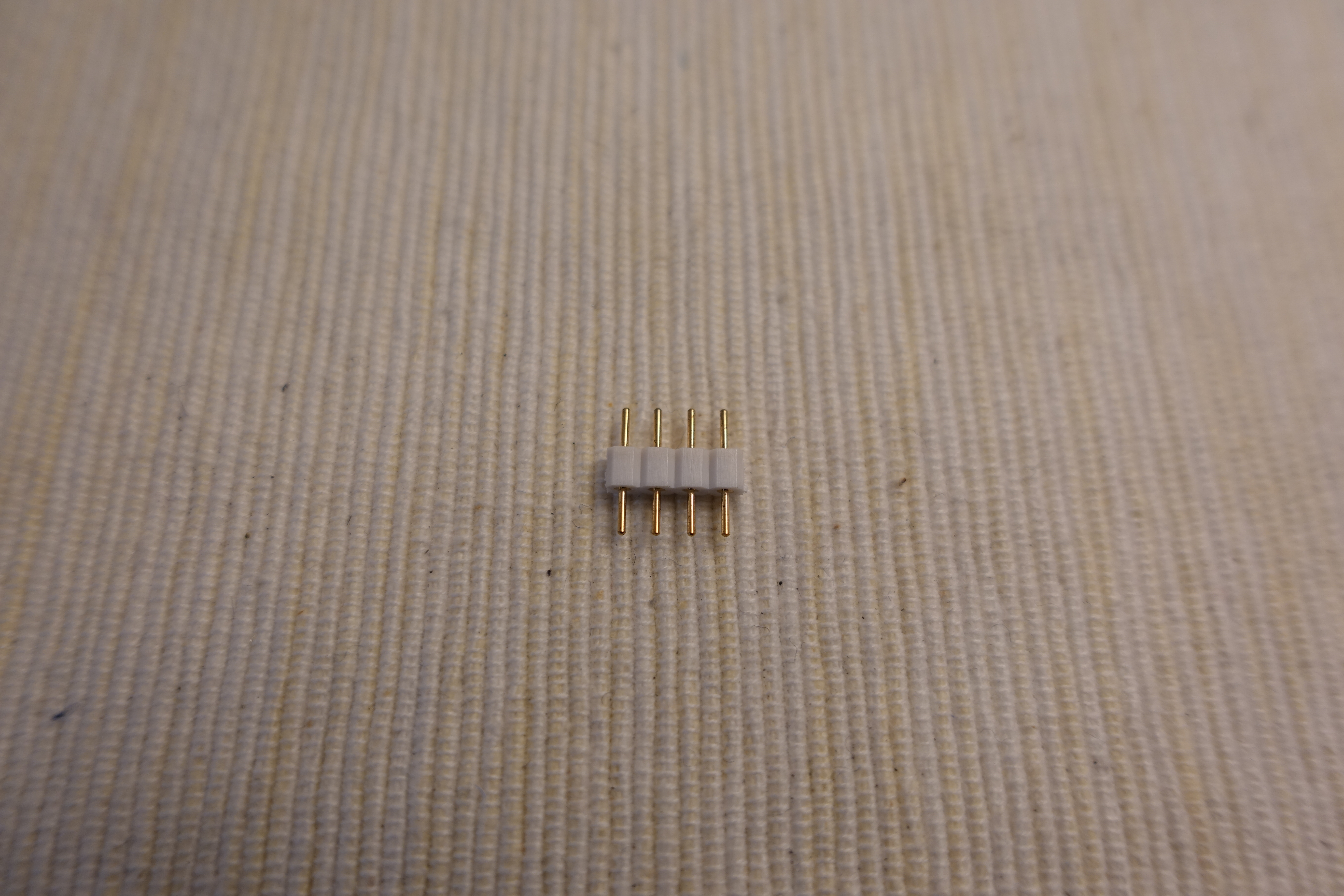
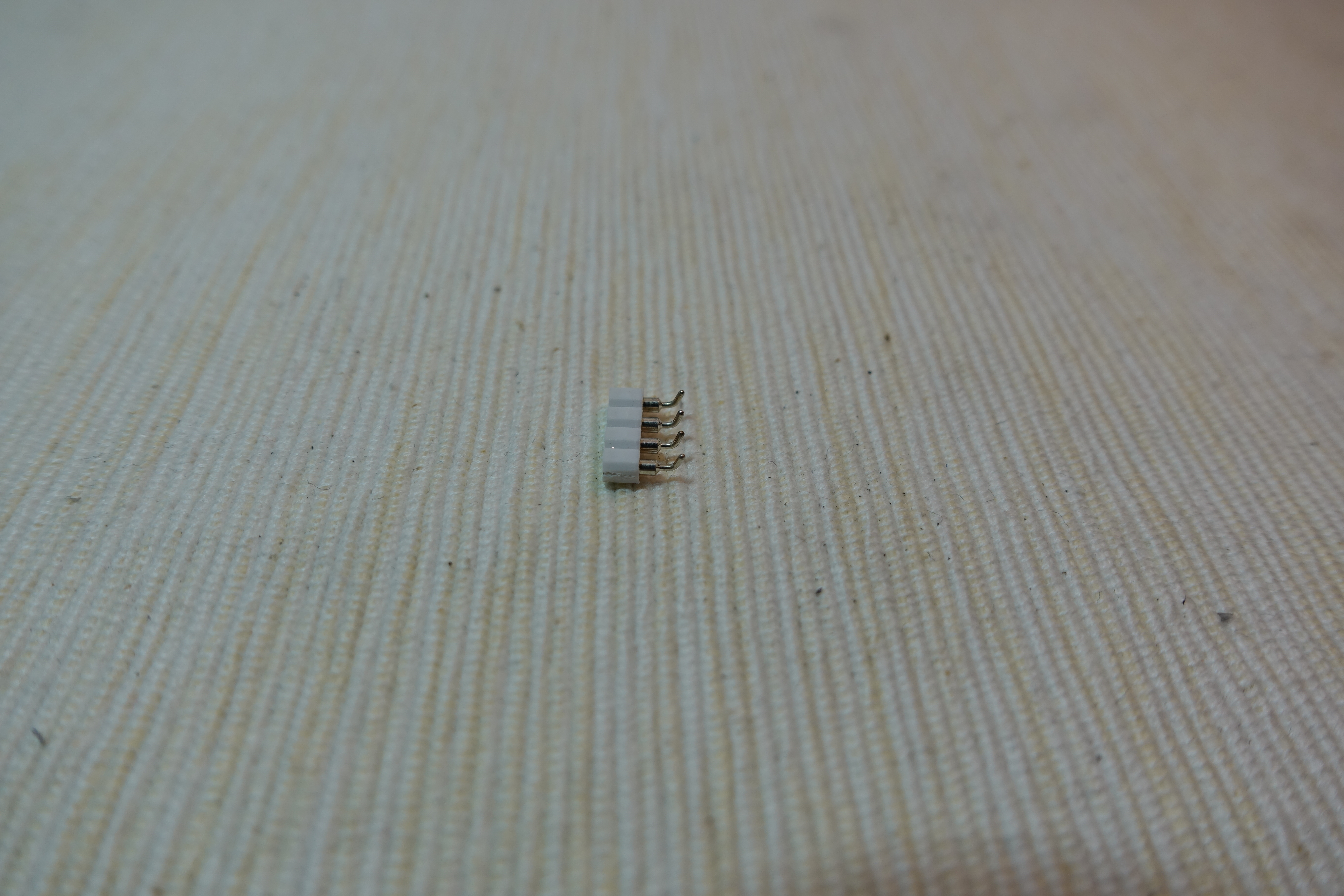
Pin Header
A 4 pins male round pin header and a 4 pins female round pin header for connecting I2C gamepad.
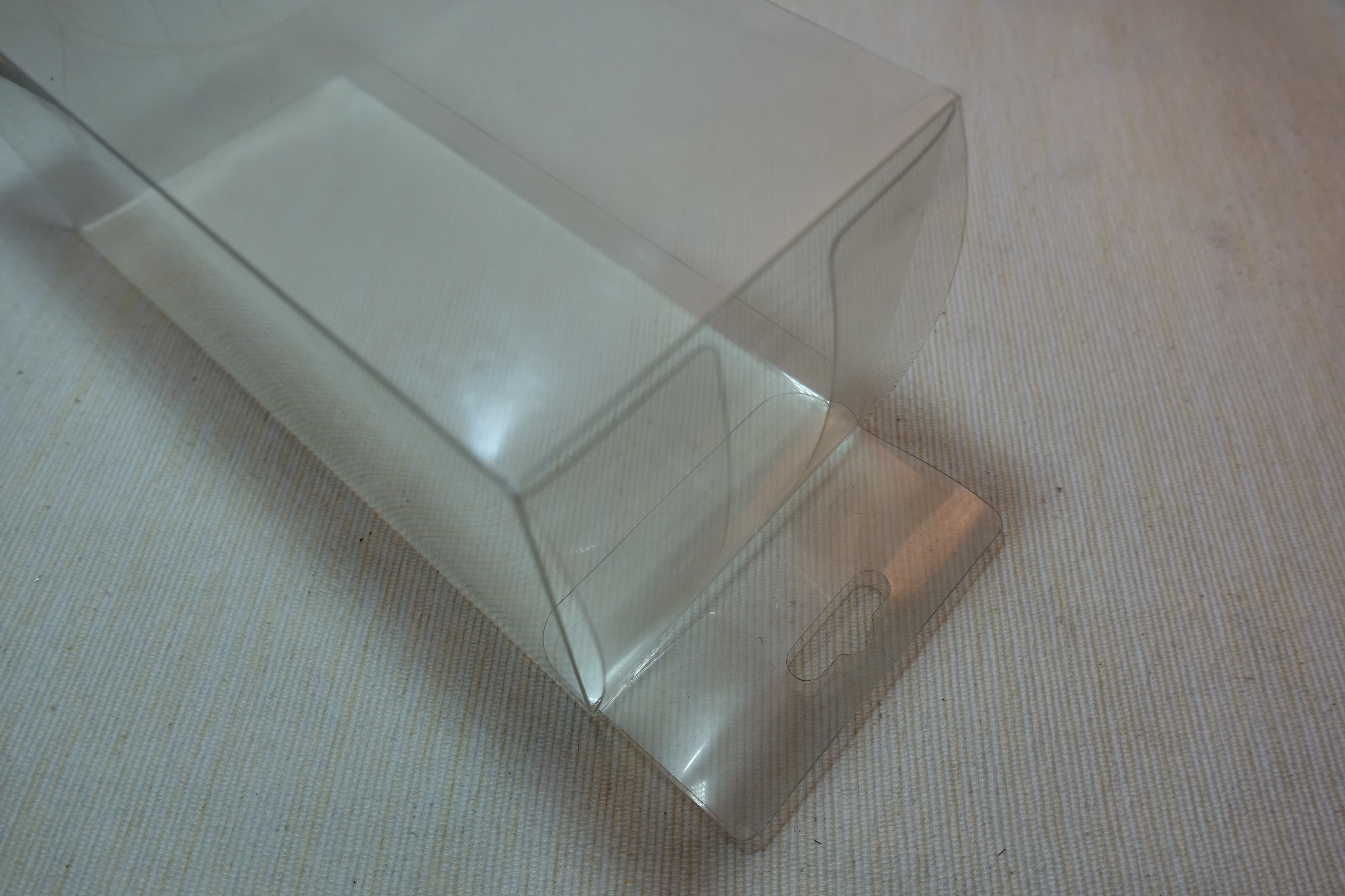
PETG Plate
A small PET/PETG plate for supporting the dev board and Lipo battery, you can easily find it in product packing.
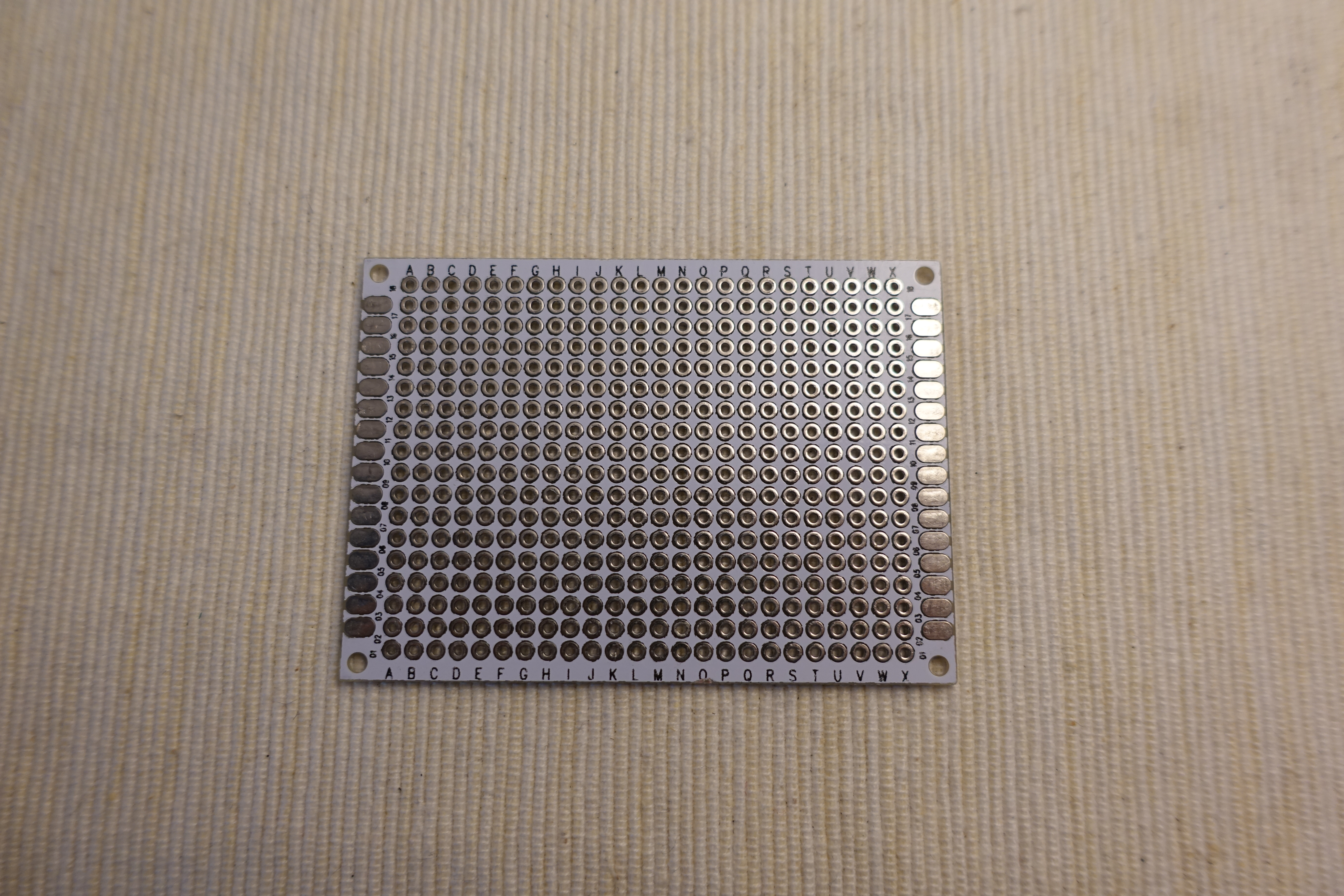
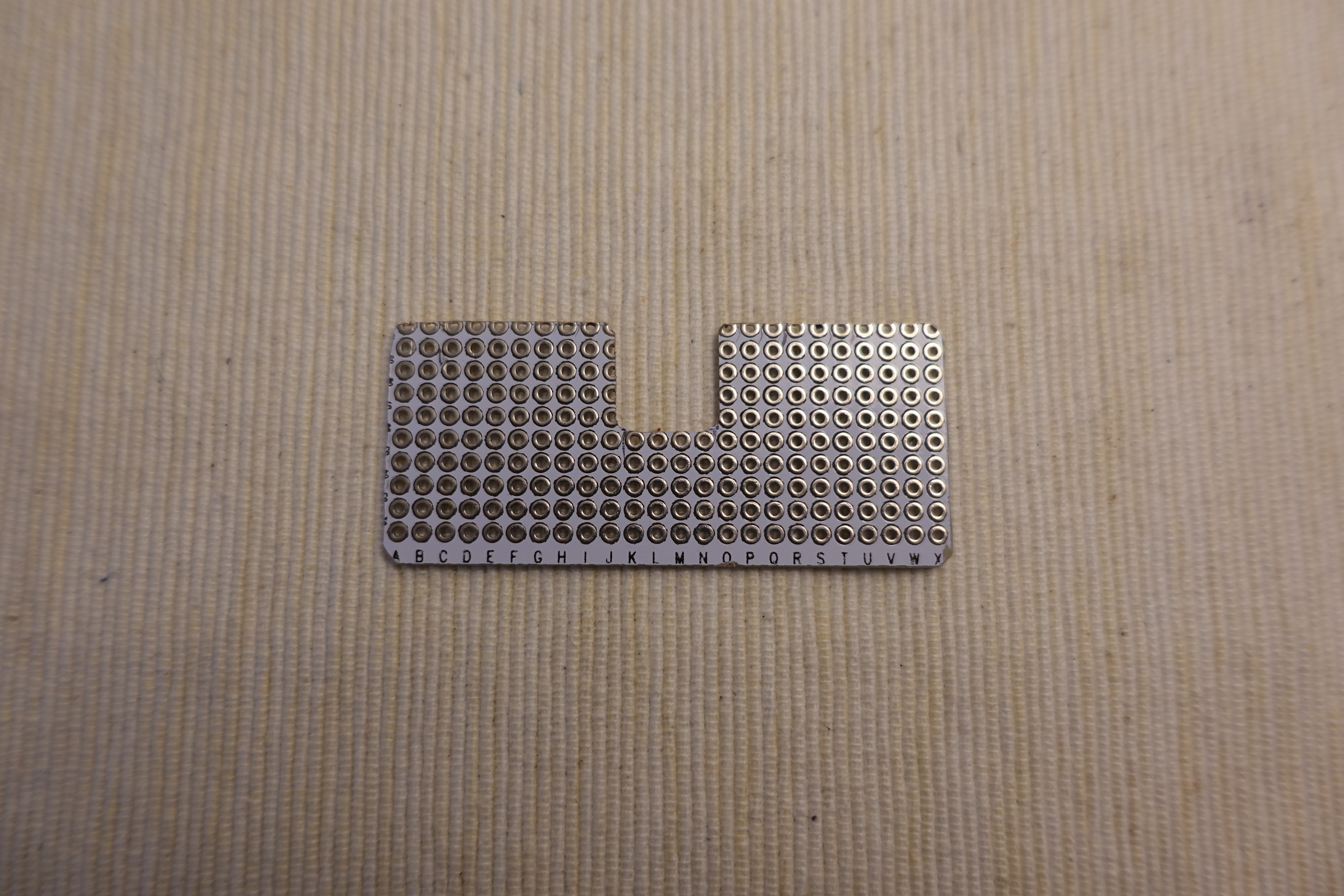
Multiple Purpose PCB
2 PCB required, 1 0.4 mm thick for supporting the Display, 1 1.2 mm thick for a I2C gamepad.
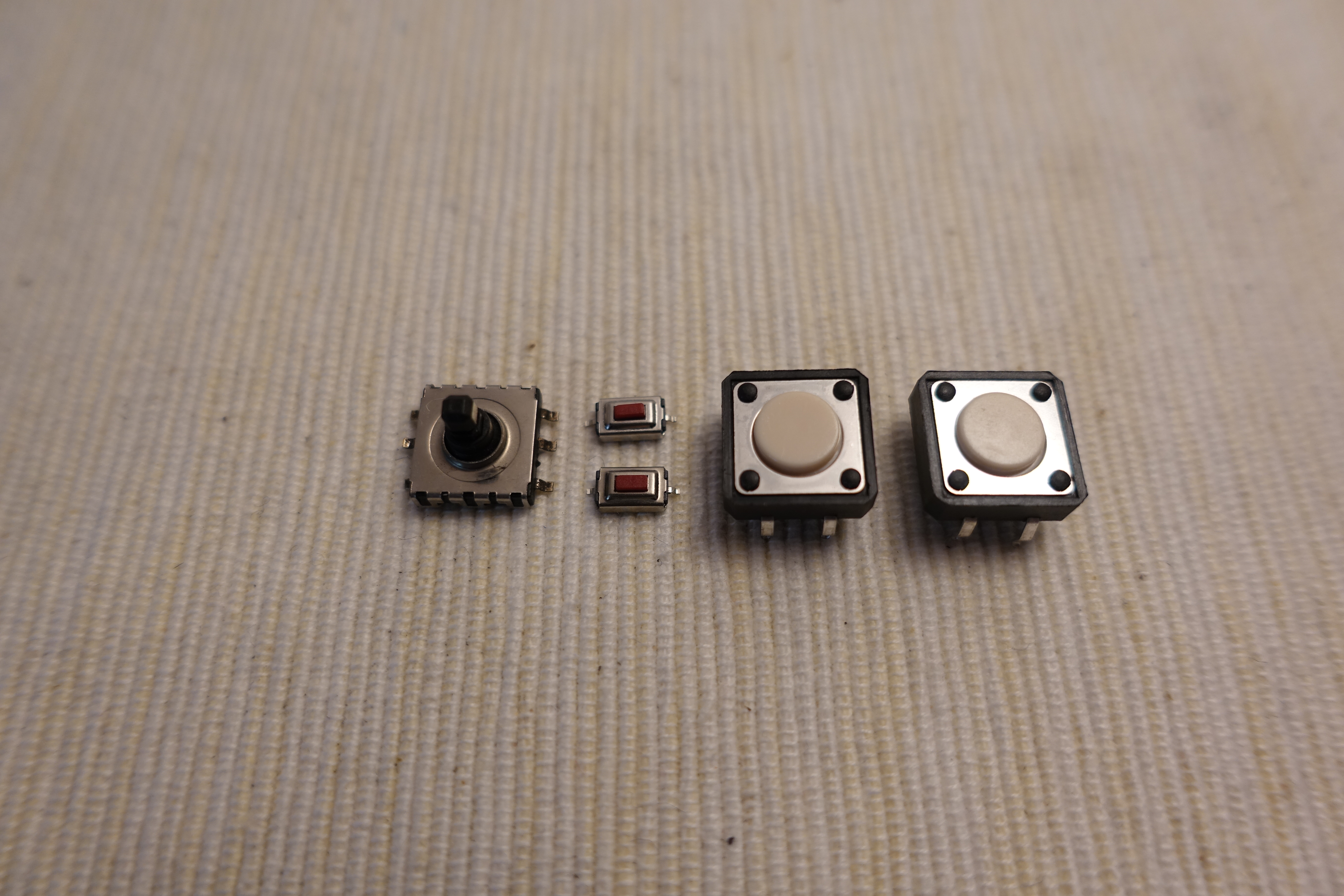
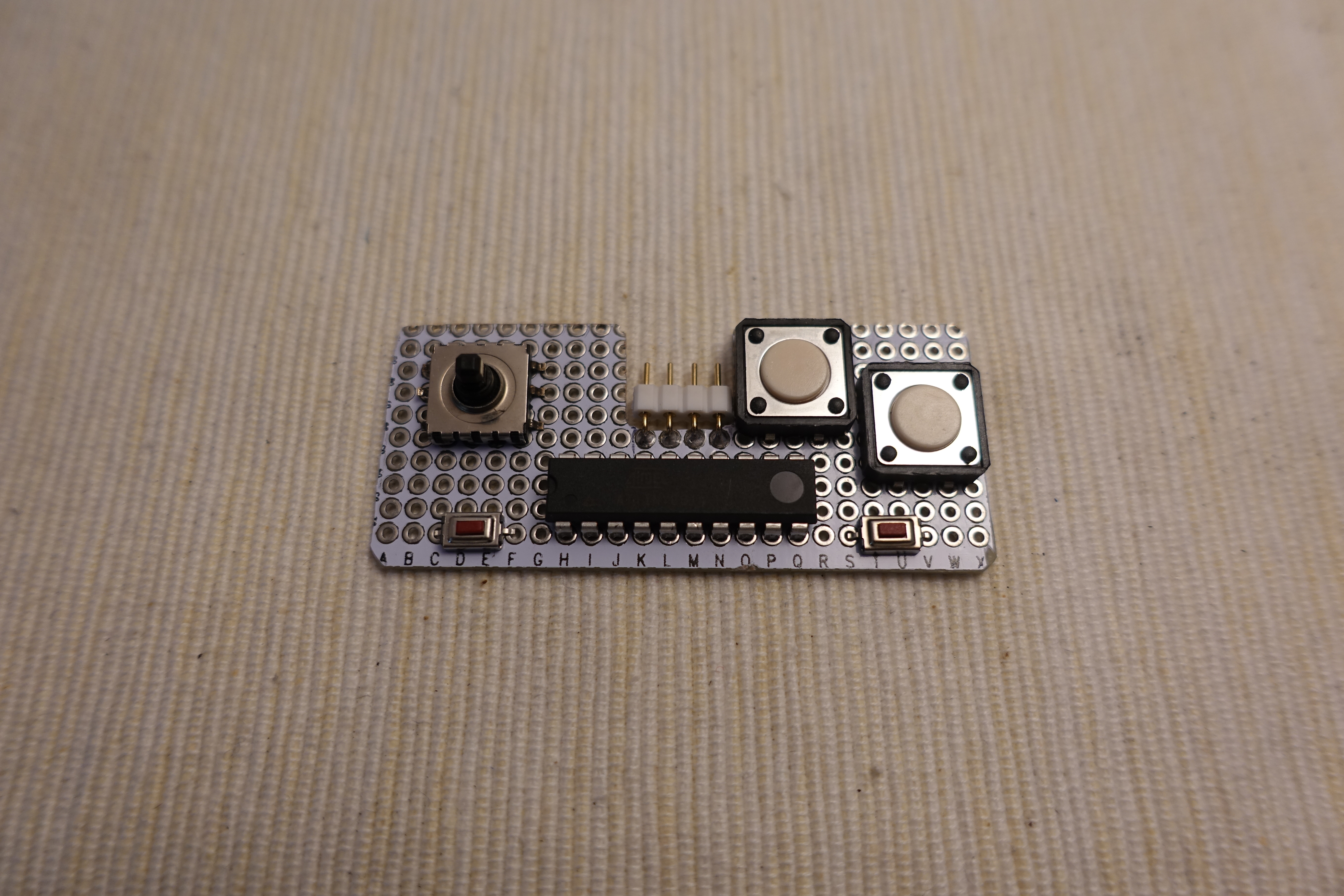
Buttons
A 5 directions button, 2 small buttons for Select and Start and 2 for A and B button.
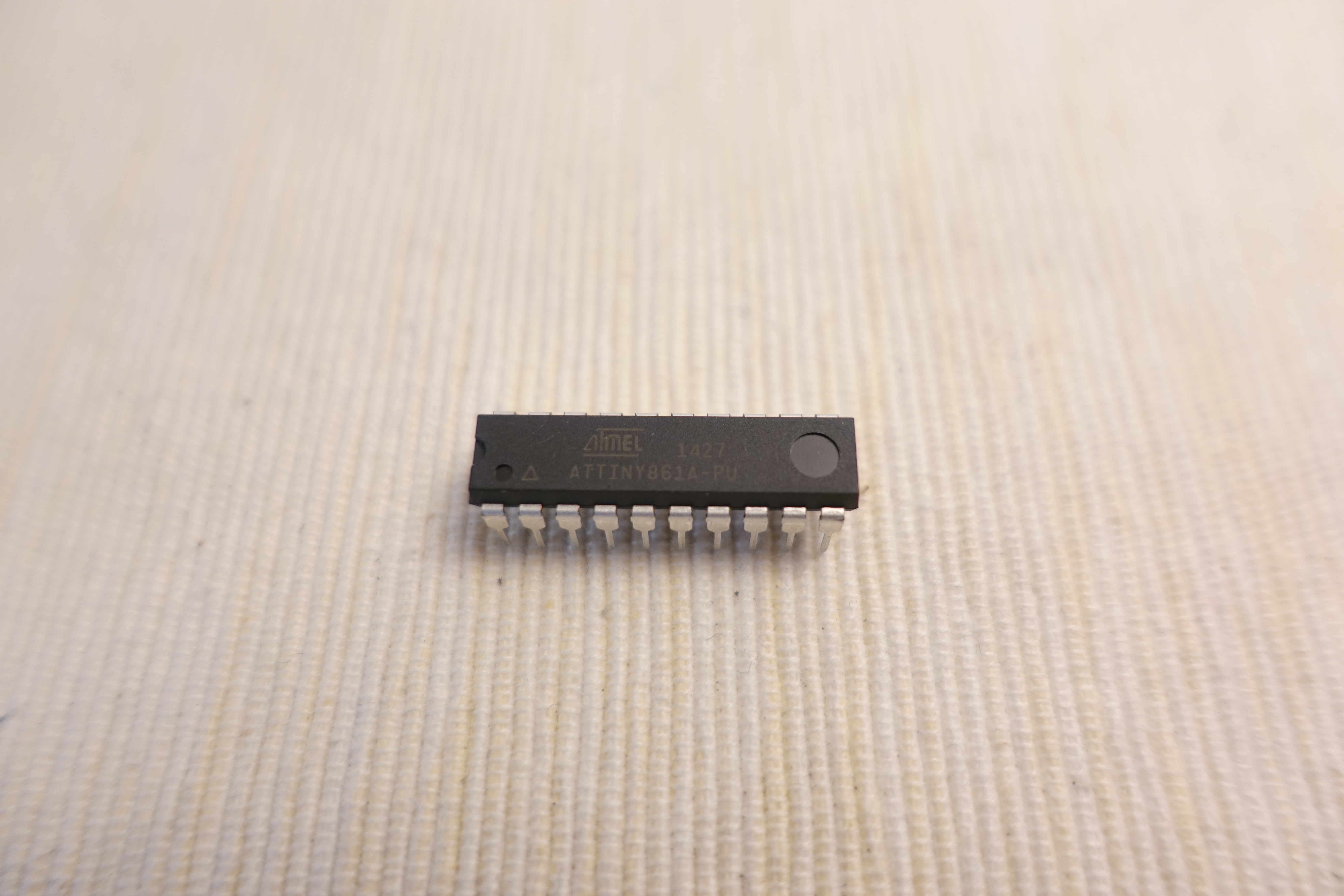
I2C Gamepad Controller
This time I use a ATtiny861 microcontroller as an I2C gamepad controller.
Others
1 SMD 12 Ohm resistor, a ISP programmer (e.g. TinyISP)
Software Preparation


Arduino IDE
Download and install Arduino IDE if not yet: https://www.arduino.cc/en/Main/Software
ATTinyCore Support
Follow the installation steps to add ATTinyCore support if not yet: https://github.com/SpenceKonde/ATTinyCore/blob/mas...
ESP-IDF
Follow the ESP-IDF get started guide to setup the development environment if not yet: https://docs.espressif.com/projects/esp-idf/en/sta...
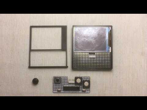
3D Printing

Download and print the case: https://www.thingiverse.com/thing:3591170
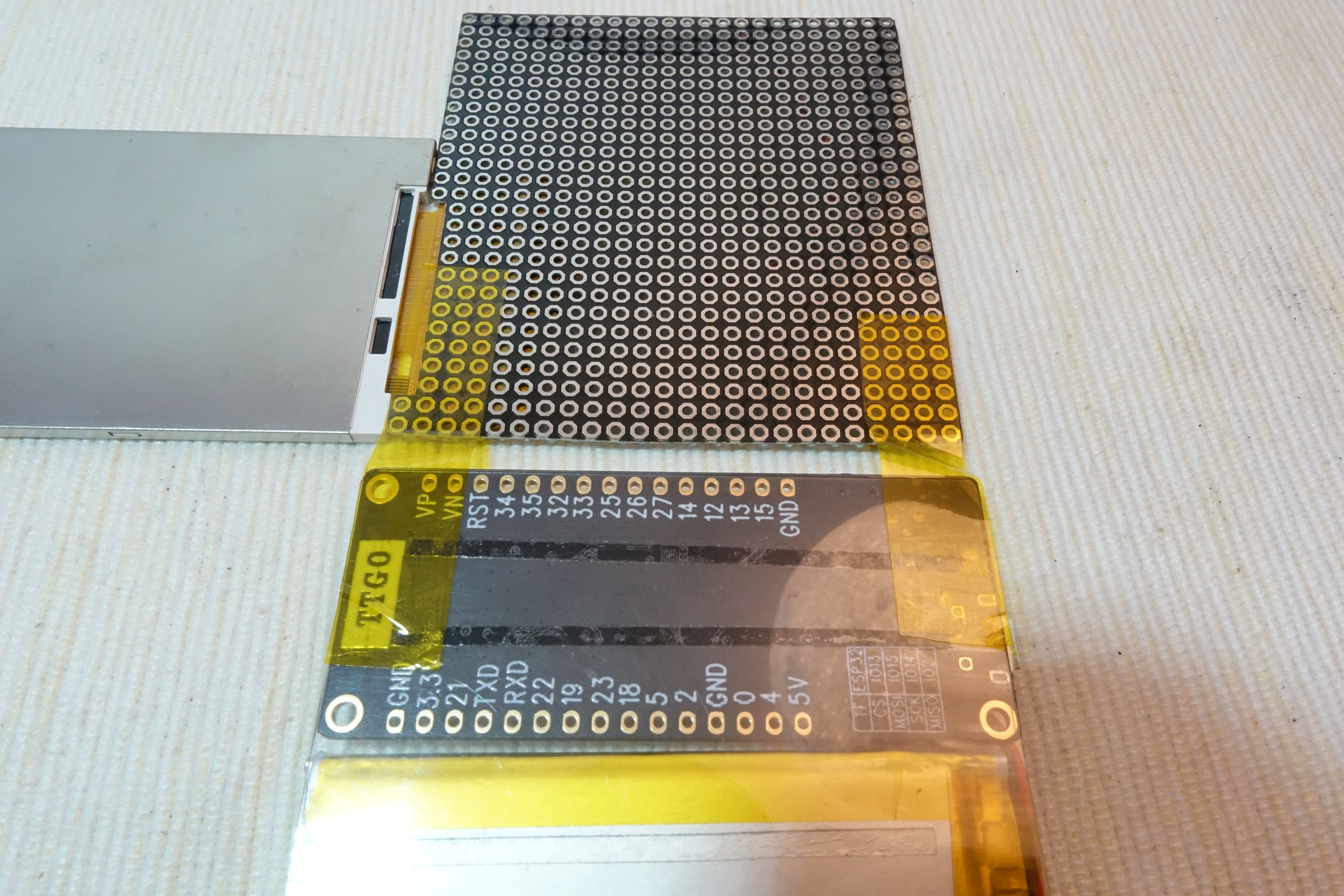
LCD Support
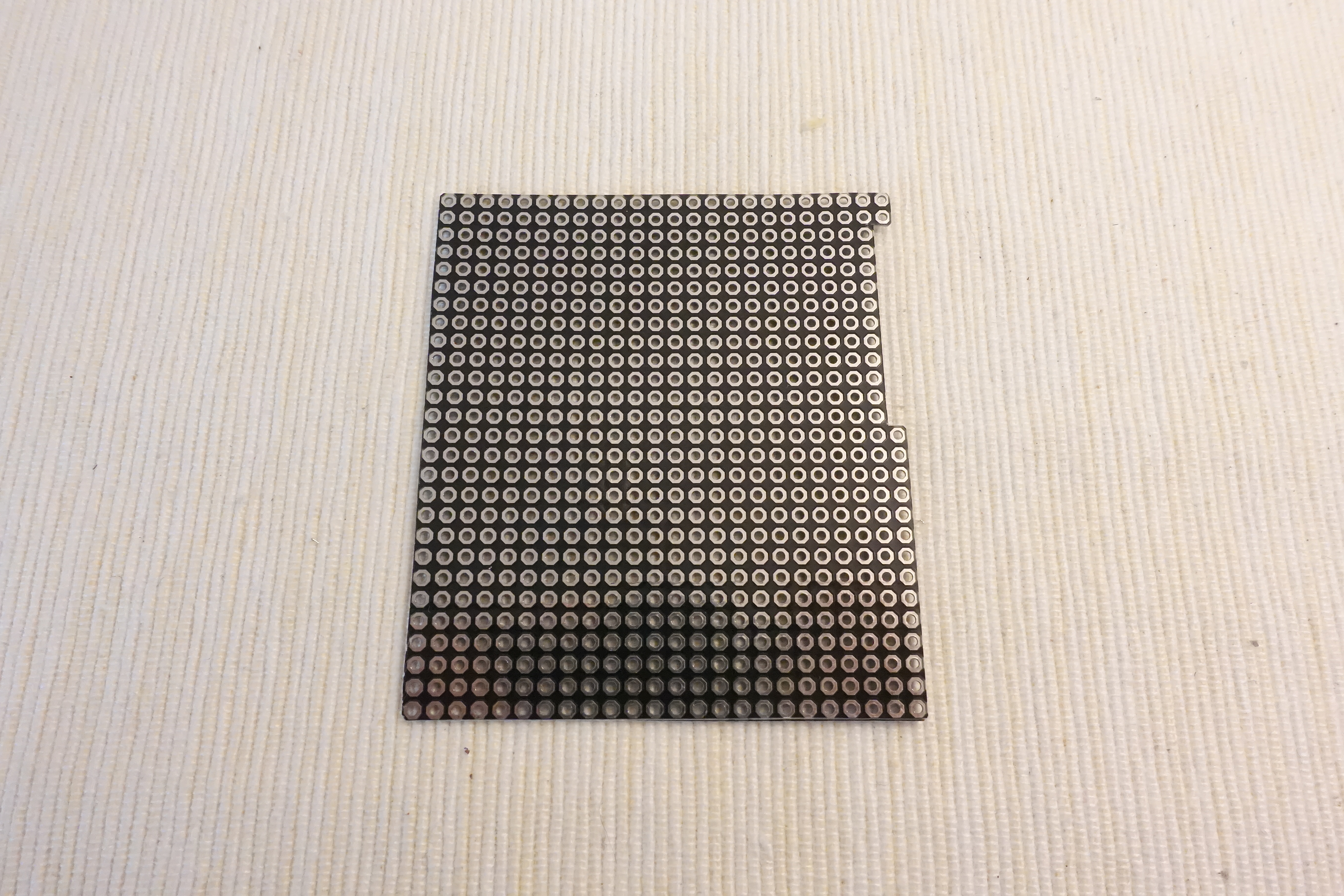
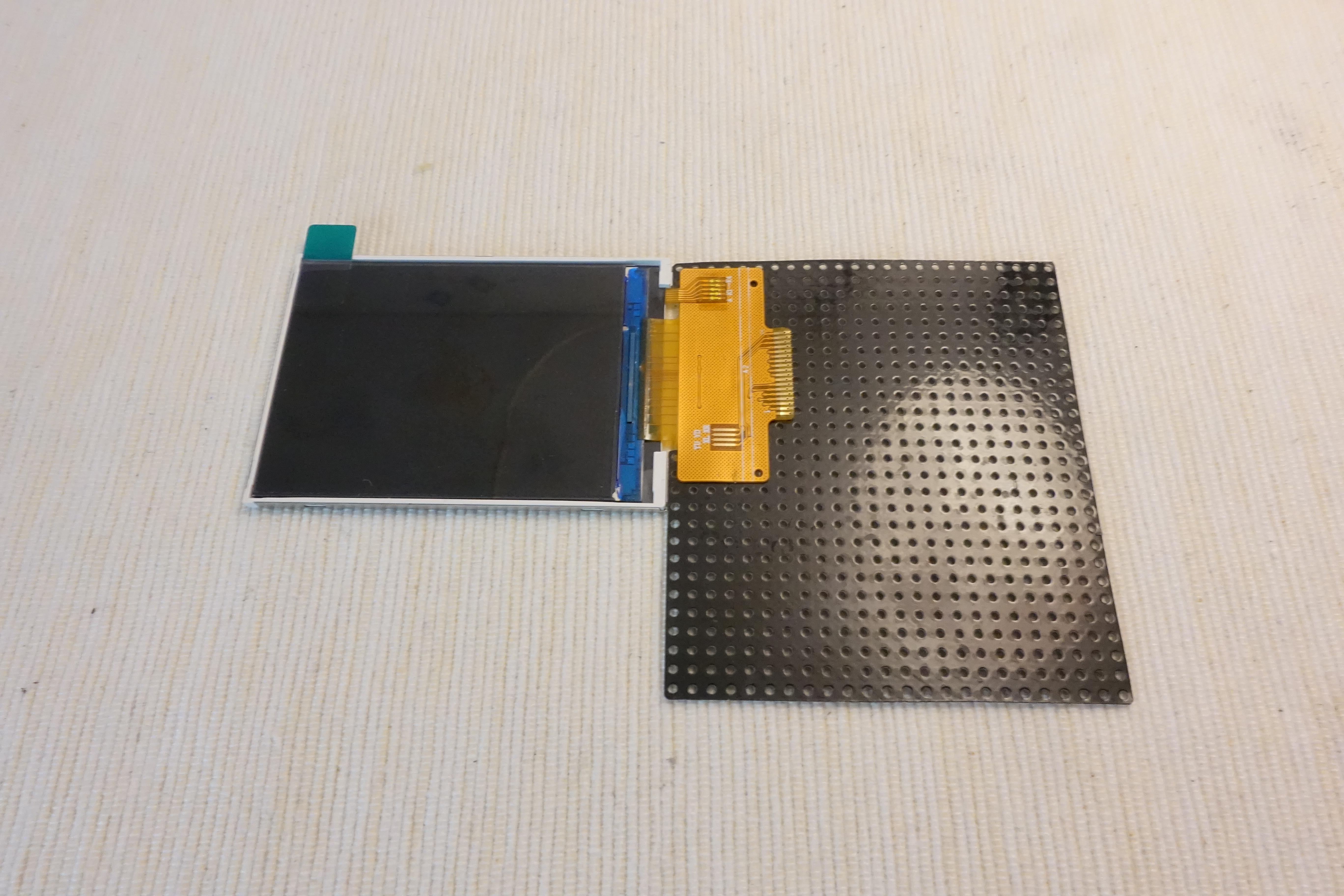
Cut a 24 x 27 holes 0.4 mm PCB for LCD support. Remember reserve some space for folding LCD FPC. Then use some double side adhesive tape fix the LCD on the PCB.
Prepare PETG Plate
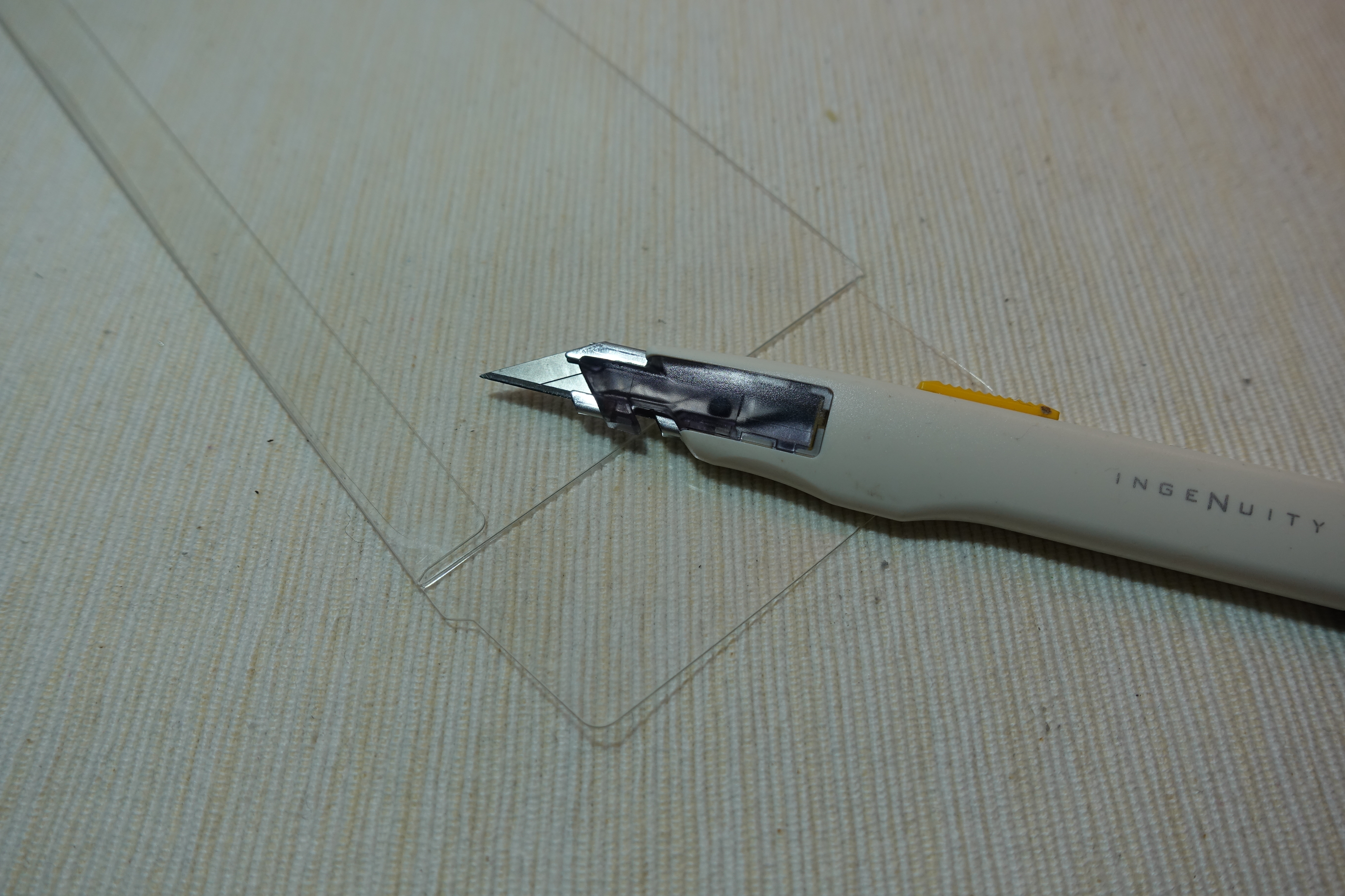
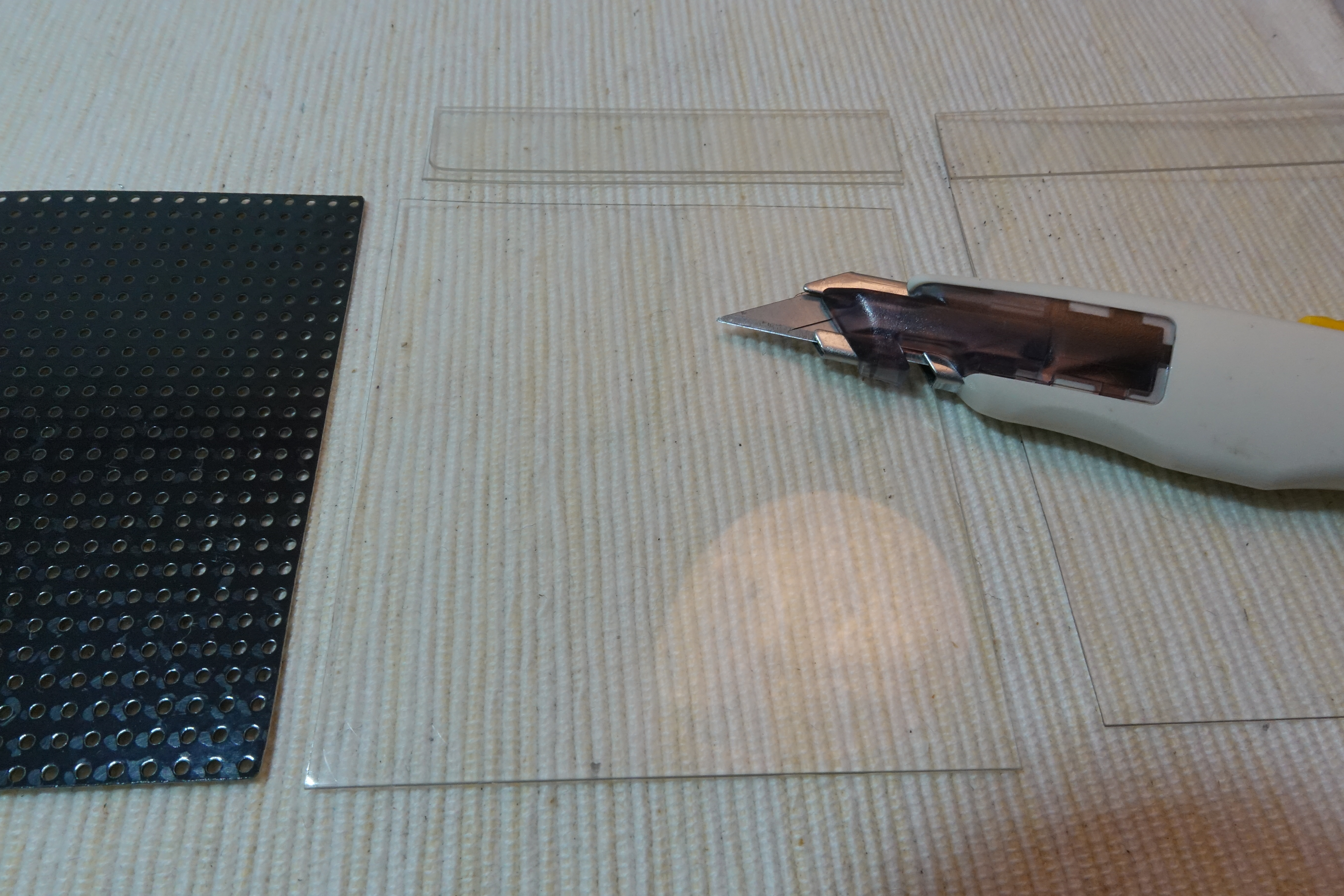
Cut out a 62 mm x 69 mm PETG plate for dev board and Lipo battery support.
Fix ESP32 Dev Board

Use double side adhesive tape to fix dev board on the PETG plate.
Fix Lipo Battery
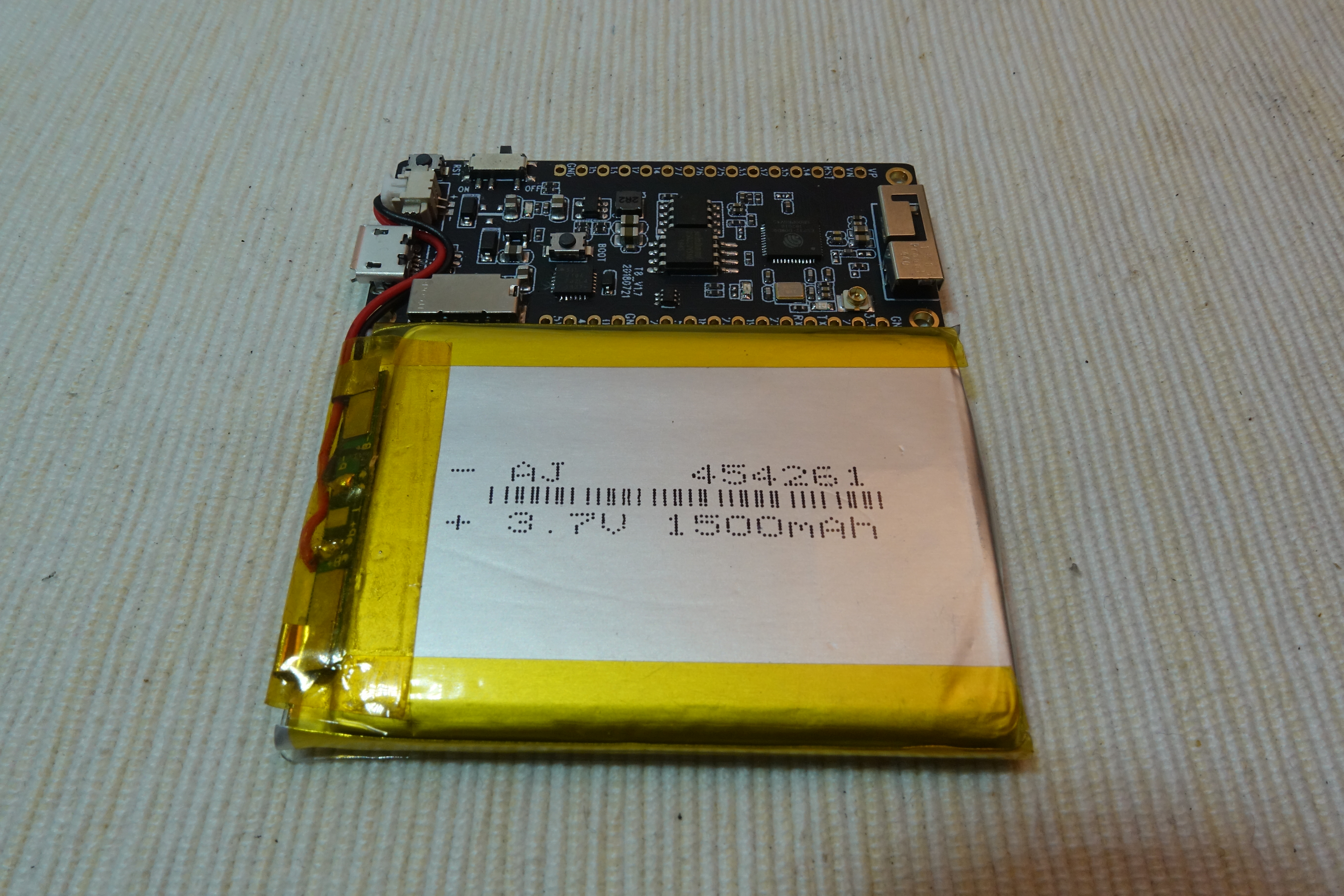
Use double side adhesive tape to fix Lipo battery besides the dev board.
Connect Battery & Dev Board
Prepare Display Pins
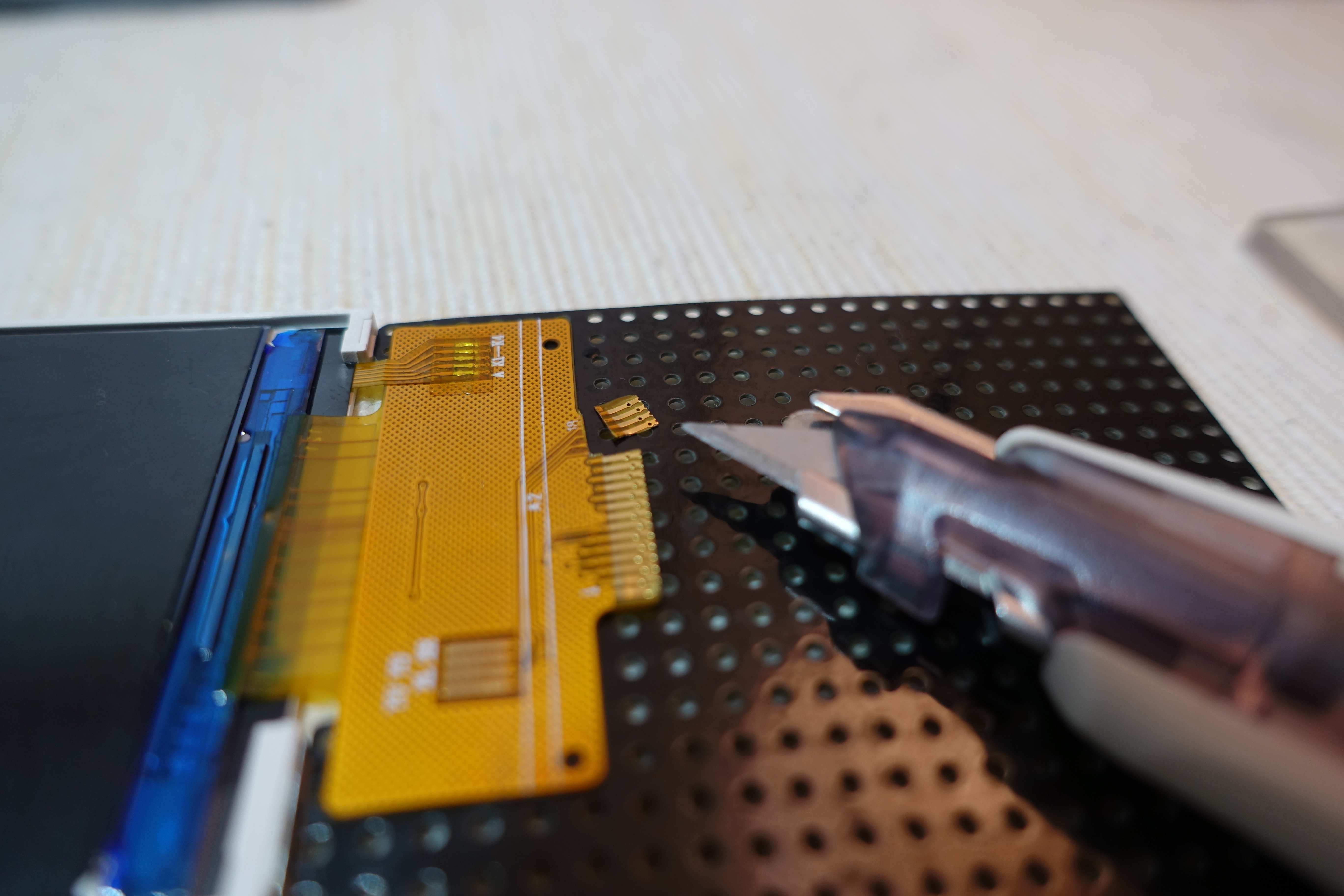
LCD display have many variation form different vendors. Please obtain the correct datasheet and read it before any patch and connection.
Some pins are reserved for touch panel. Since this LCD do not have touch panel, simply cut out those pins can reduce the disturbance.
Connect GND Pins
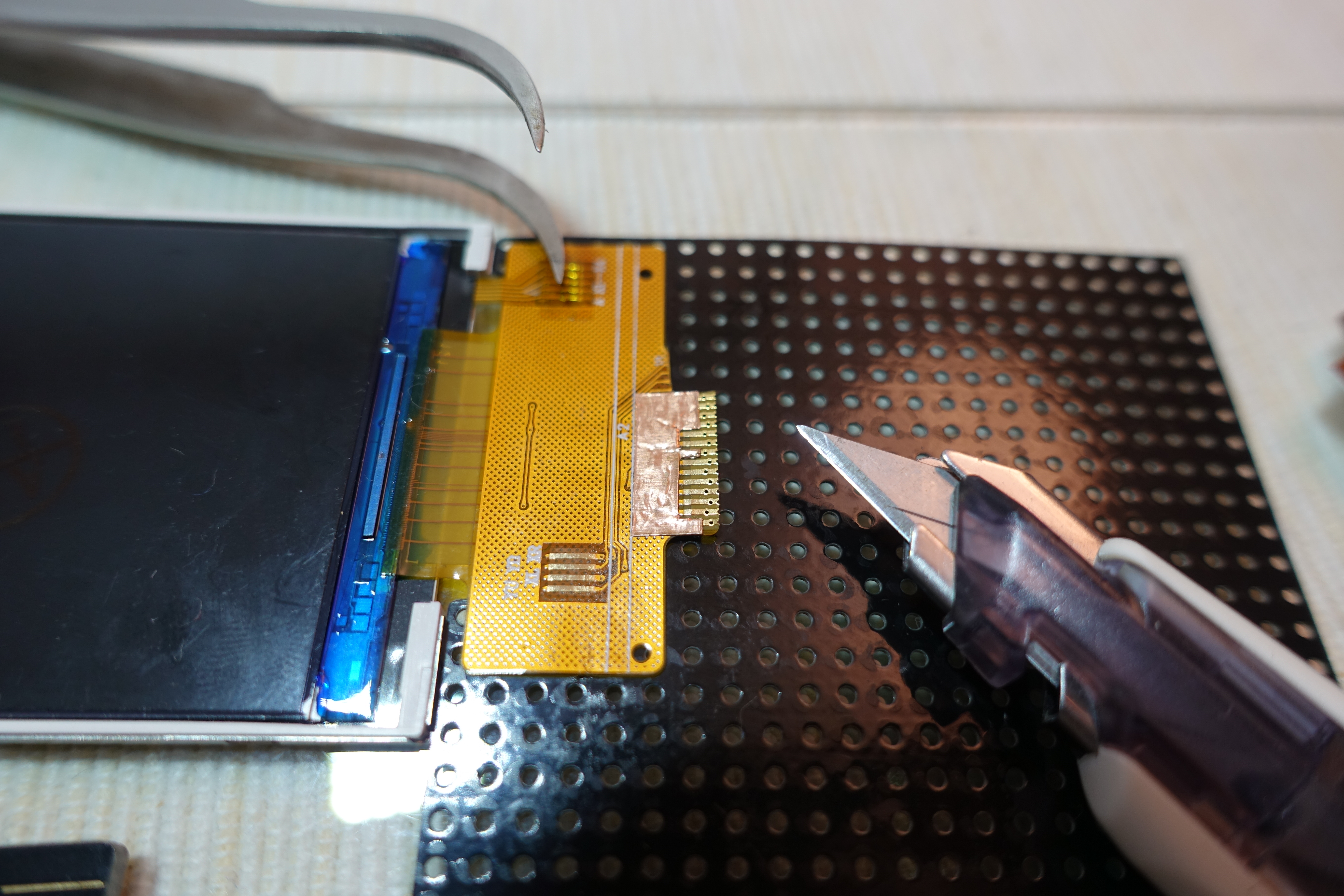
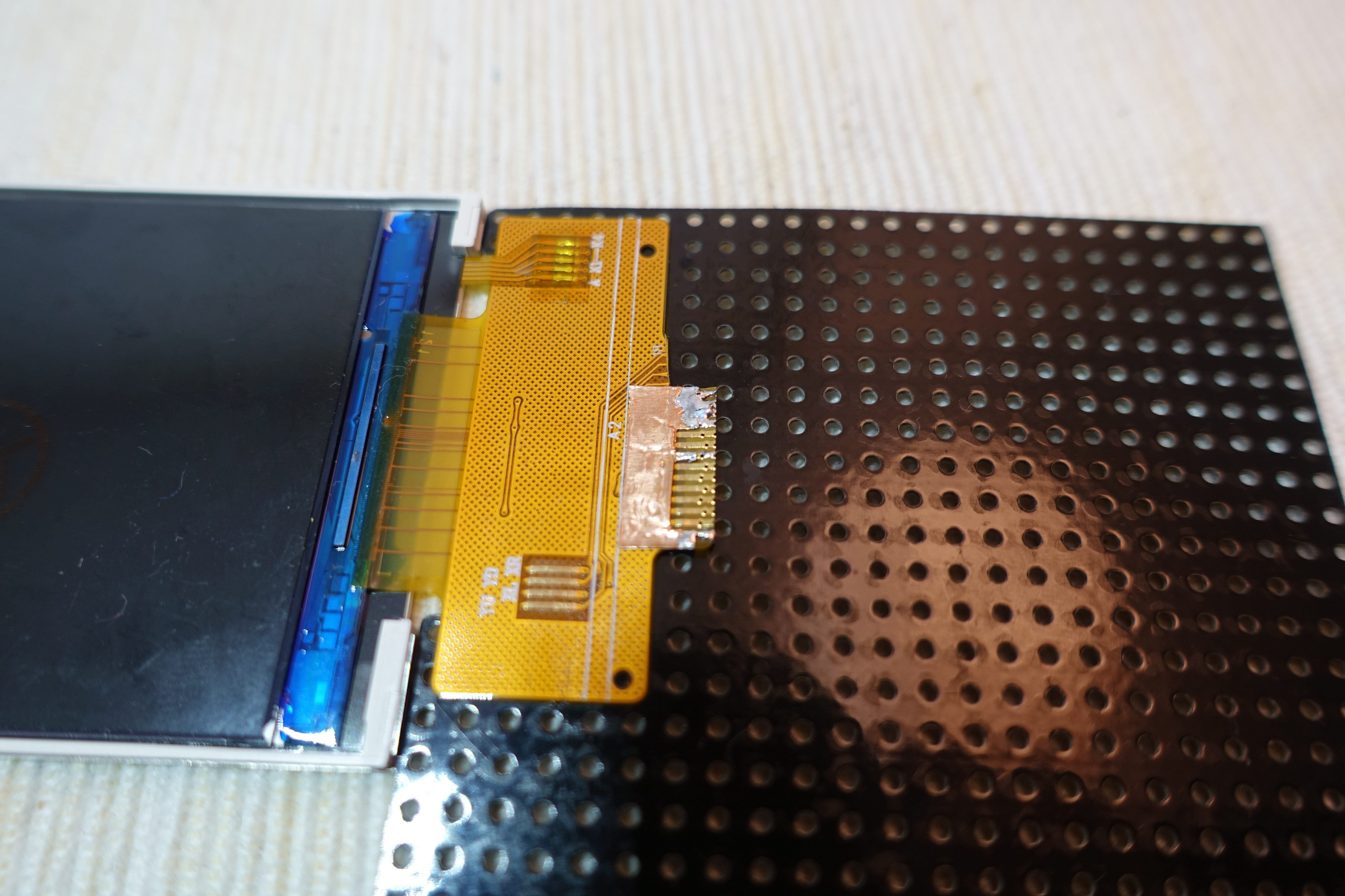
In most case, there are few pins require connect to GND. To reduce soldering effort, I cut a copper tape shape to reach all the GND pins and then soldering altogether.
Connect Vcc Pins
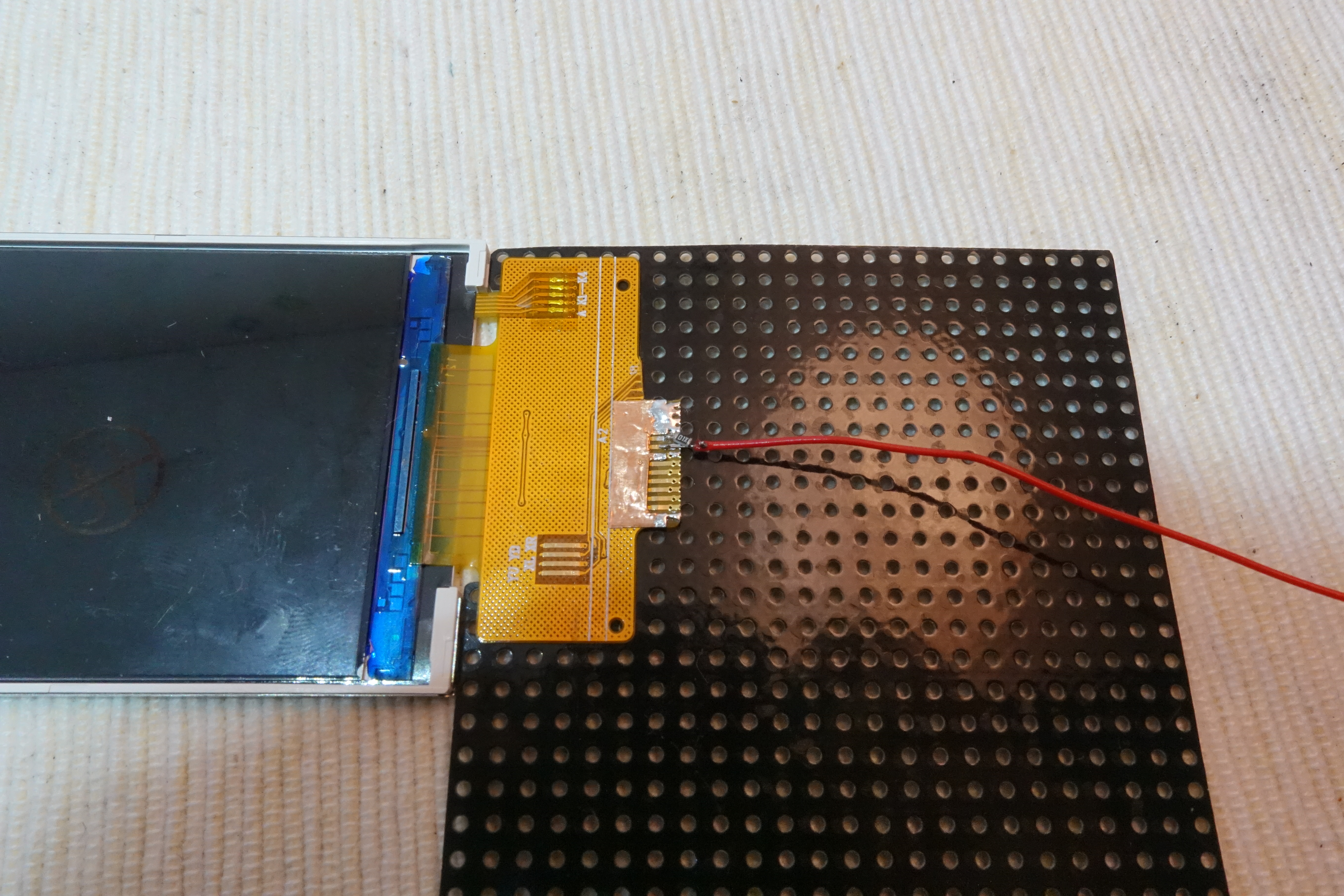
There are 2 pins required connect to Vcc, LCD power and LED power. According to data sheet, LCD power can direct connect to dev board 3.3 V pin but LED power operate a little bit lower than 3.3 V. So it is better add a SMD resistor in the middle, e.g. 12 Ohm resistor.
Connect LCD & Dev Board Support
use tape connect LCD support and dev board support together. Both support should reserve around 5 mm gap for folding.
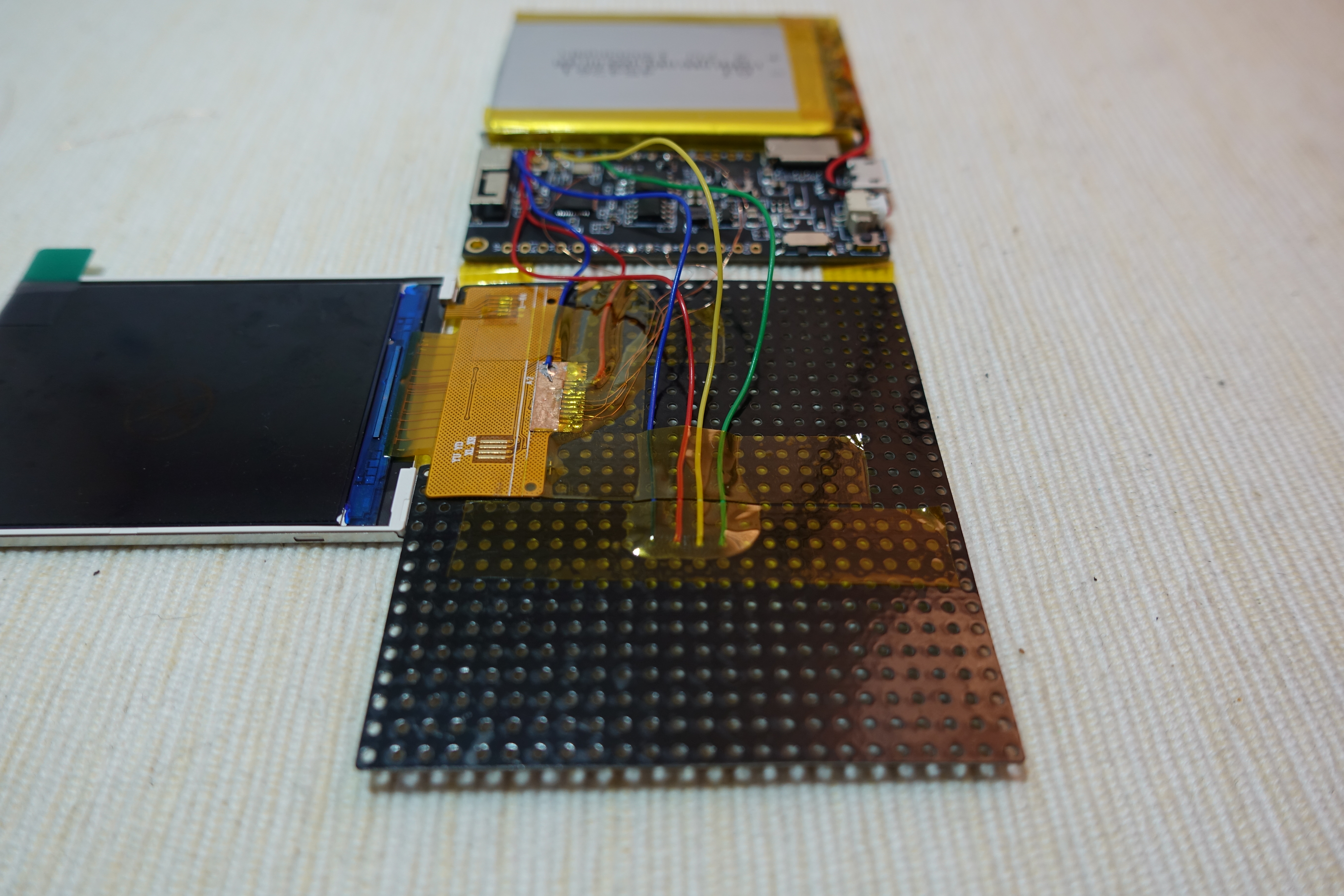
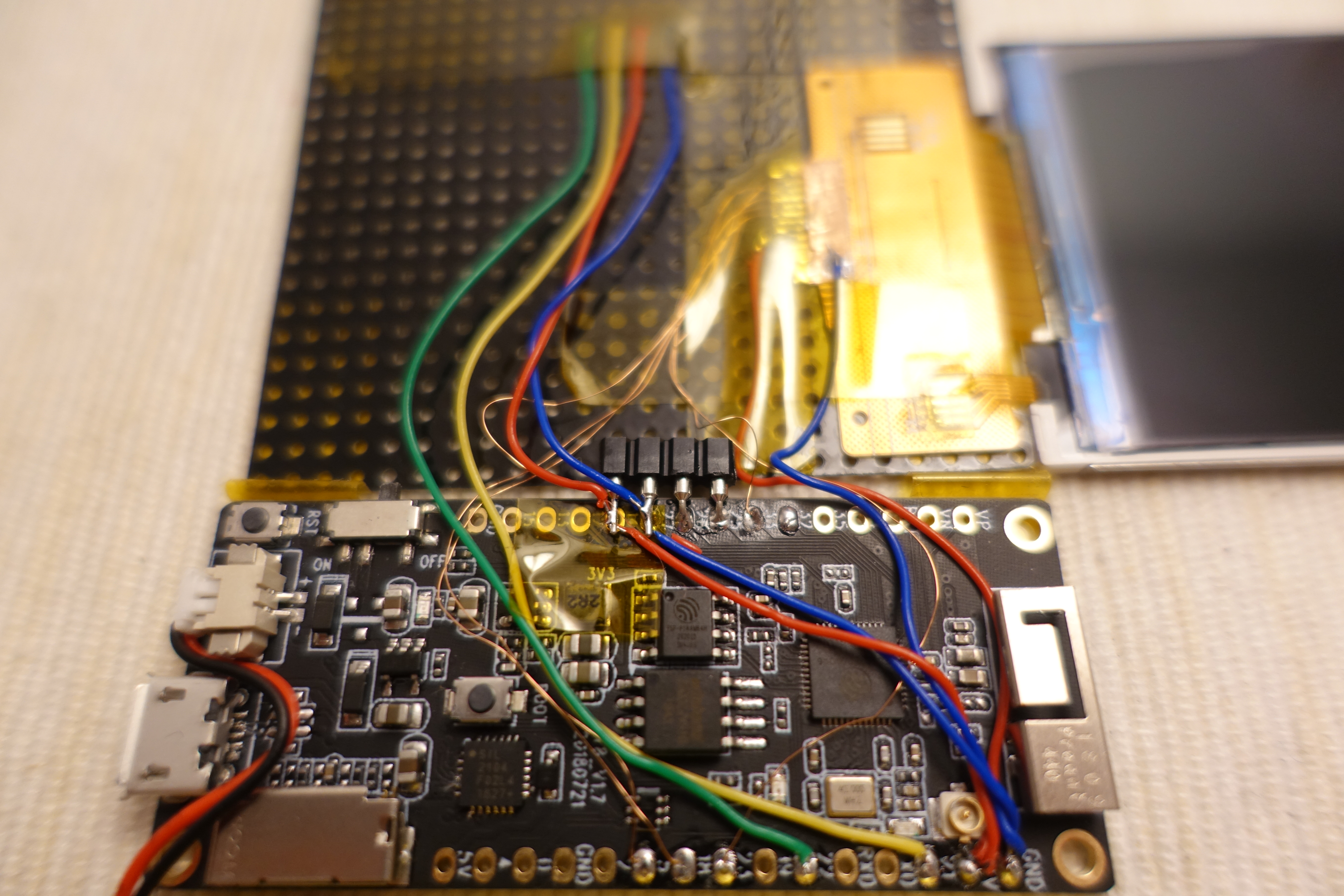
Connect SPI Pins

Here are the connection summary:
LCD     ESP32
GND  -> GND
RST  -> GPIO 33
SCL  -> GPIO 18
DC   -> GPIO 27
CS   -> GPIO 5
SDI  -> GPIO 23
SDO  -> not connected
Vcc  -> 3.3 V
LED+ -> 12 Ohm resistor -> 3.3 V
LED- -> GND
Flash Program


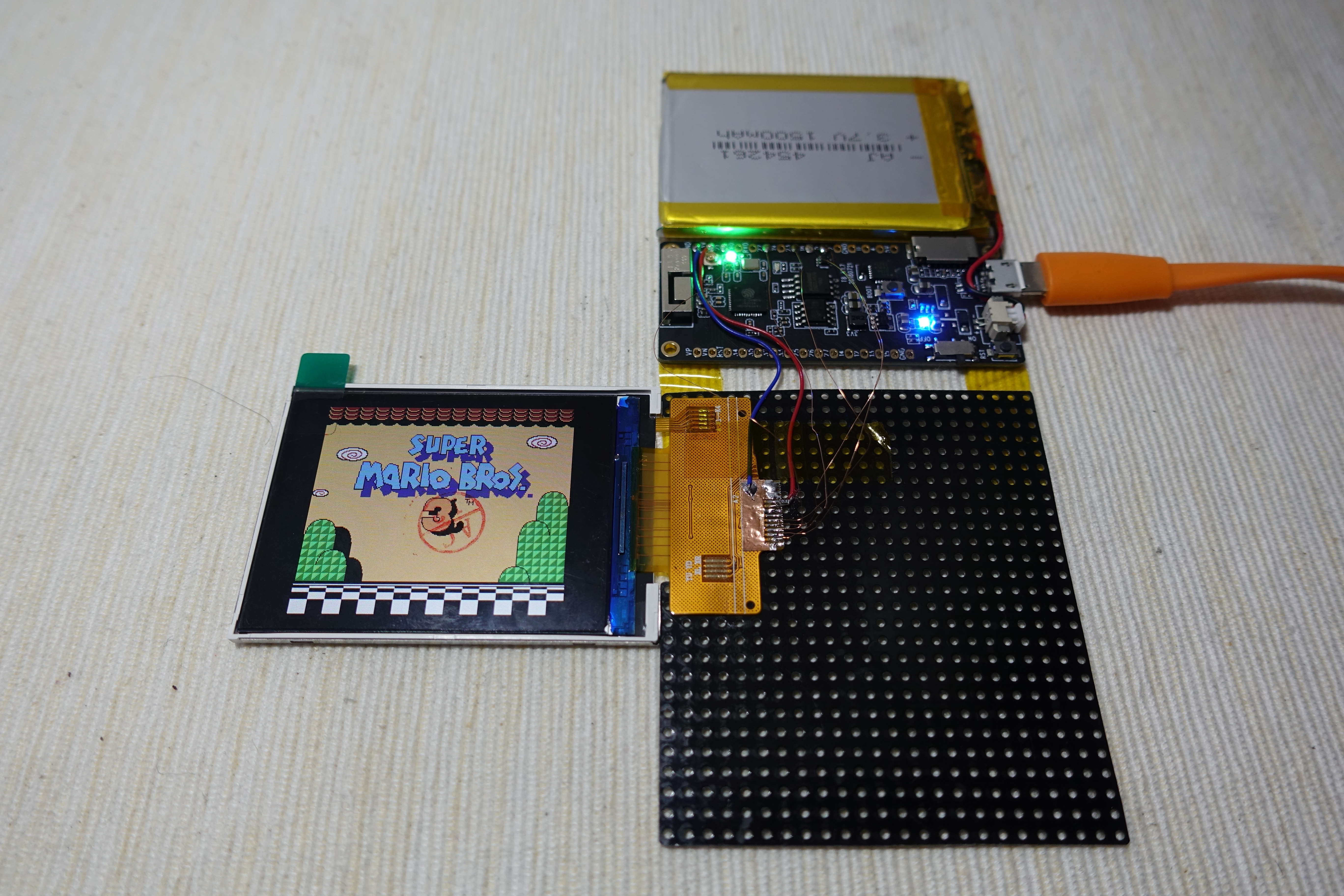
- Download the source code at GitHub: https://github.com/moononournation/esp32-nesemu
- Under source code folder, run "make menuconfig"
- Select "Nofrendo ESP32-specific configuration"
- Select "Hardware to run on" -> "Custom Hardware"
- Select "LCD Type" -> "ST7789V LCD"
- Fill pin settings: MISO -> -1, MOSI -> 23, CLK -> 18, CS -> 5, DC -> 27, RST -> 33, Backlight -> -1, IPS -> Y
- Exit and Save
- Run "make -j5 flash"
- Run "sh flashrom.sh PATH_TO_YOUR_ROM_FILE"
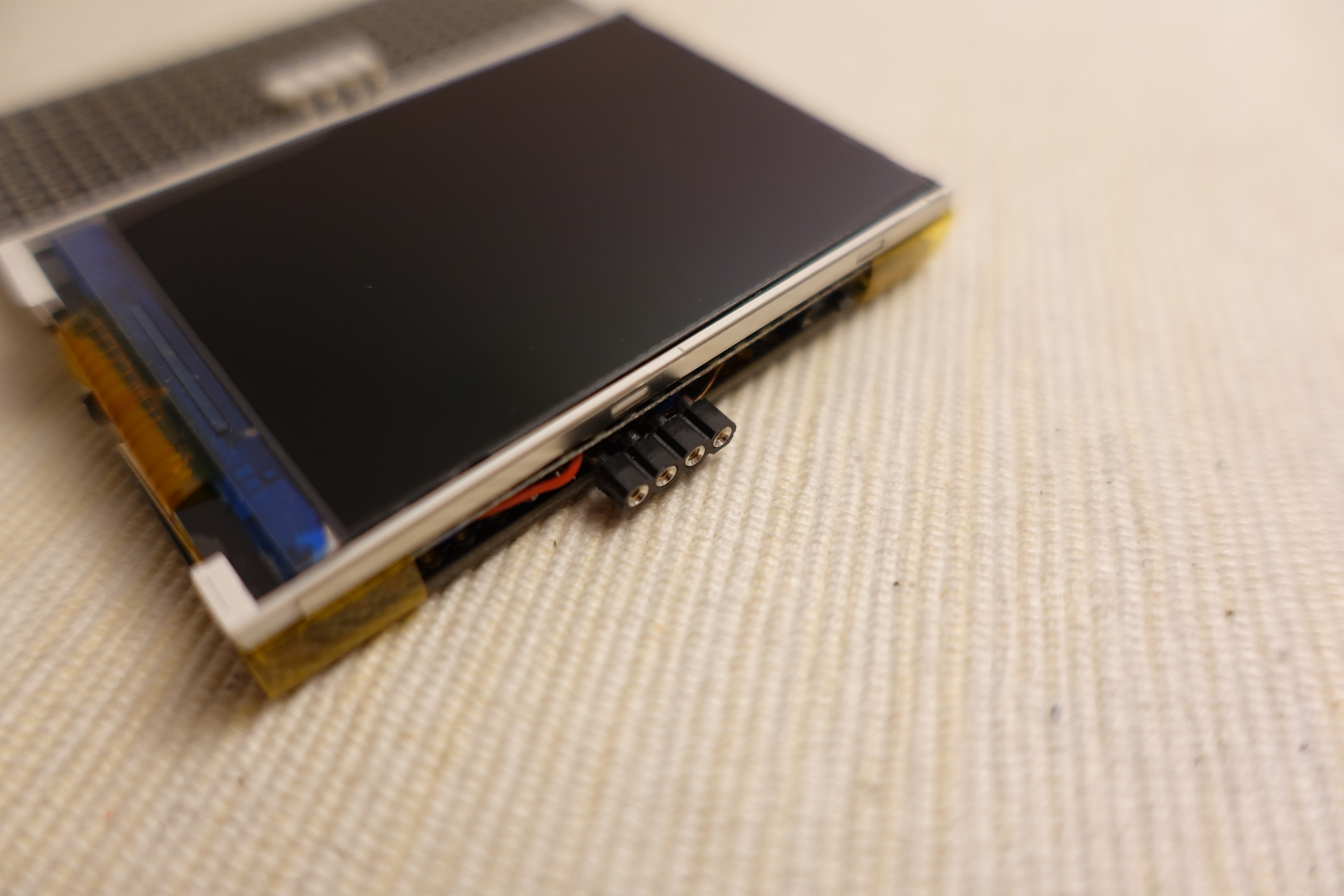
I2C Connector
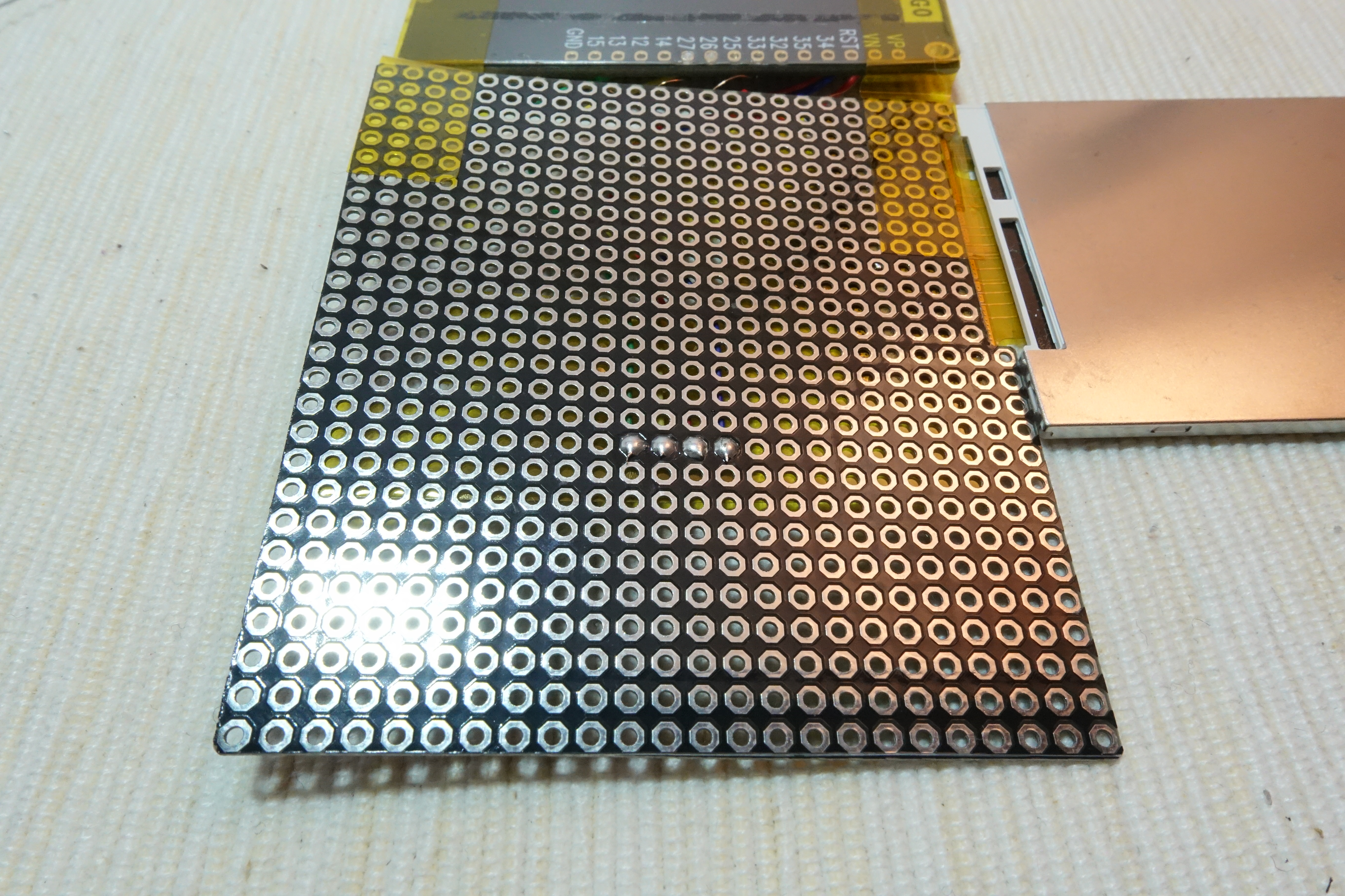
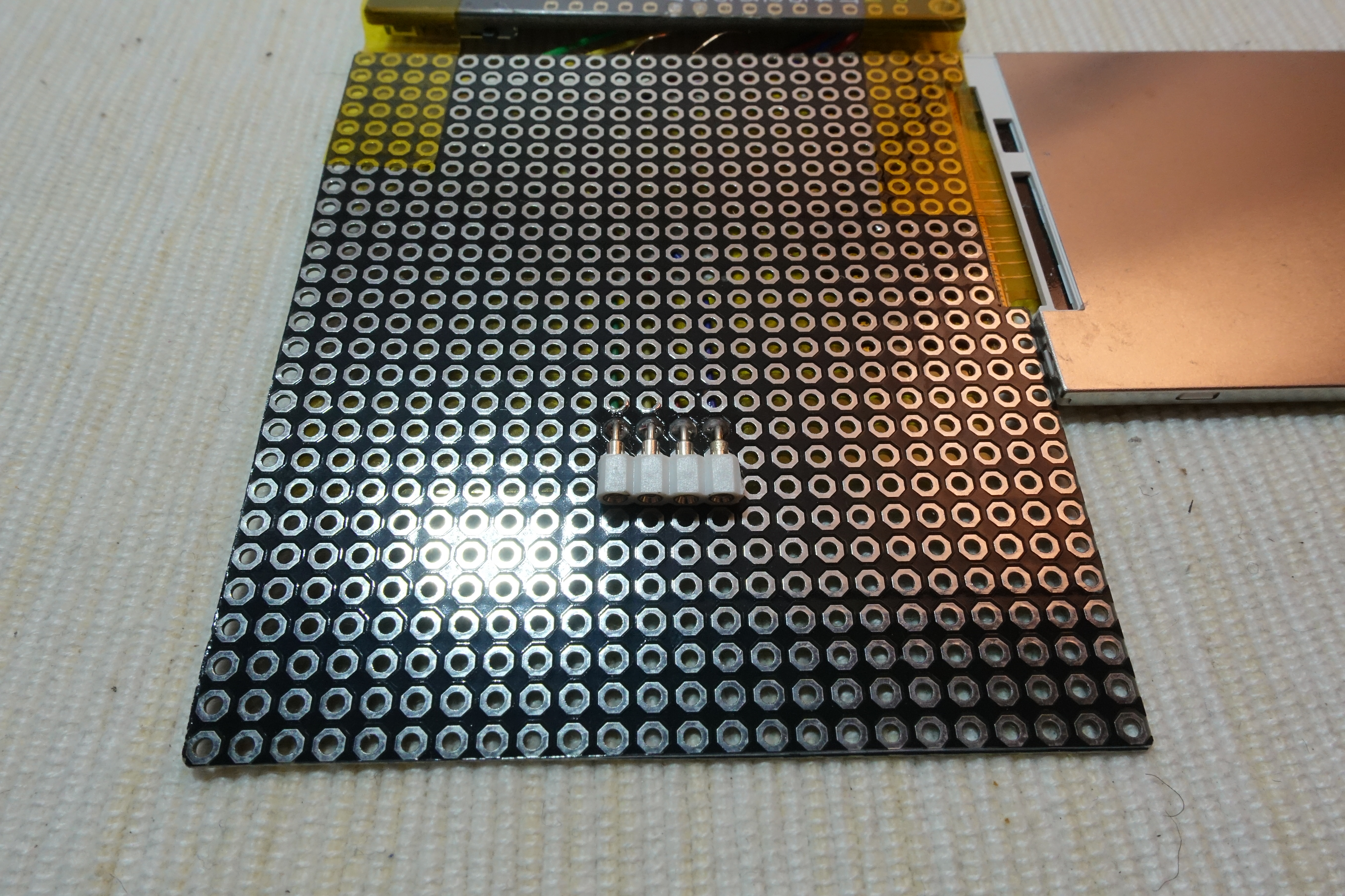
Breakout the I2C pins, ESP32 default I2C pins are:
Pin 1 (SCL) -> GPIO 22
Pin 2 (SDA) -> GPIO 21
Pin 3 (Vcc) -> 3.3 V (no 5 V power while powered by Lipo battery)
Pin 4 (GND) -> GND
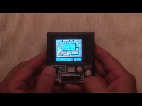
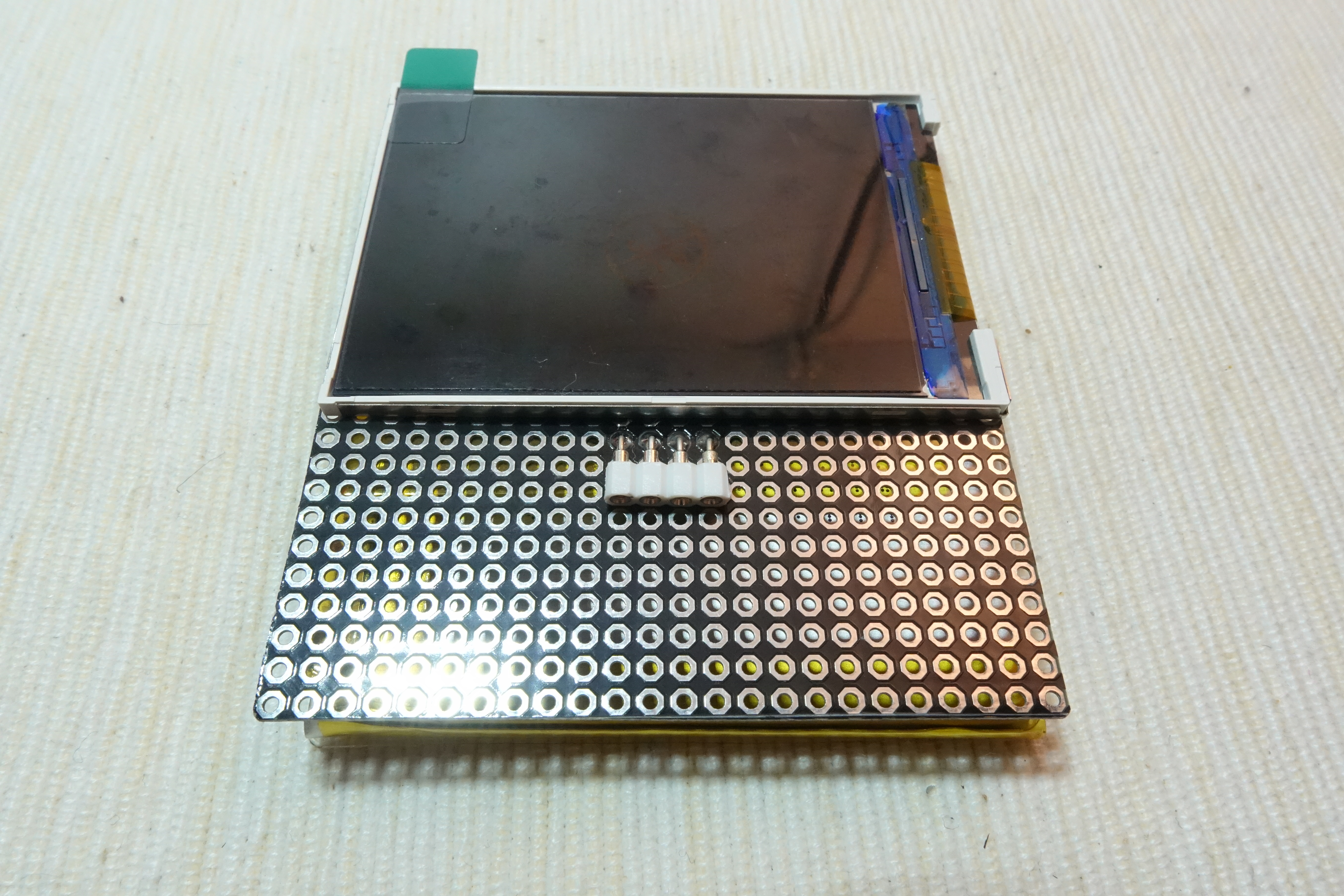
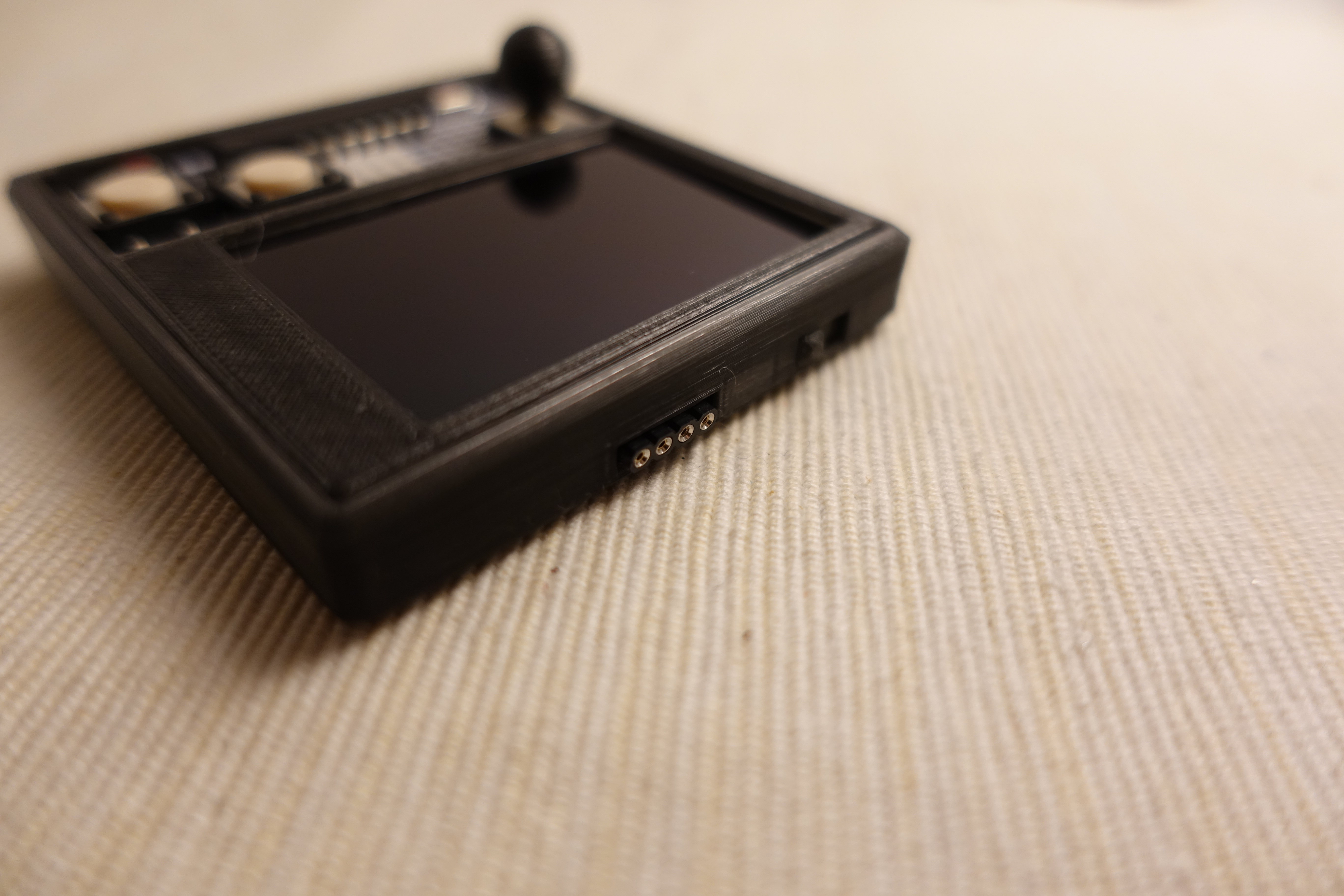
Assembly Part 1
Follow the video steps to fold and squeeze all the parts into the case.
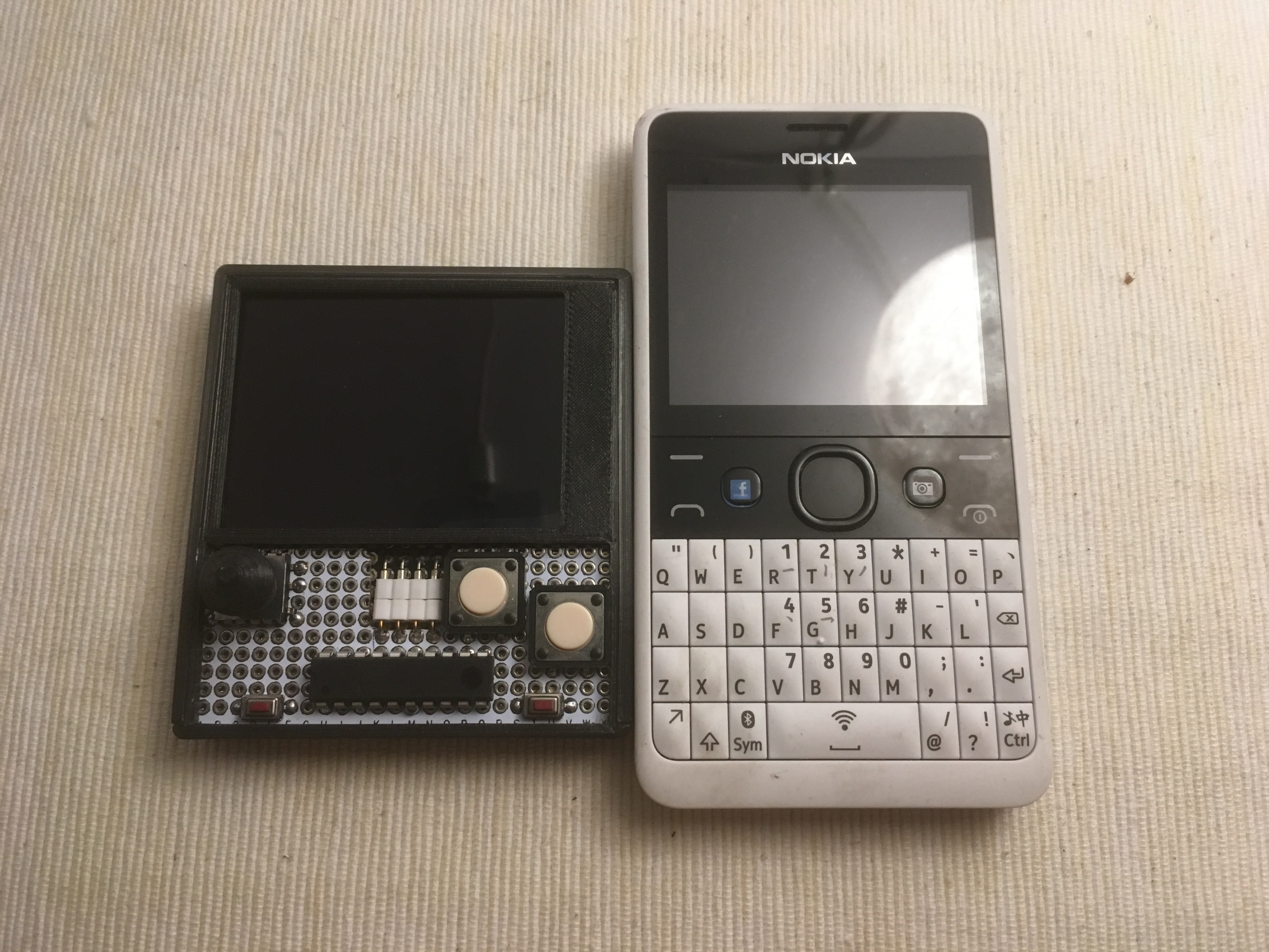
Prototype I2C Gamepad
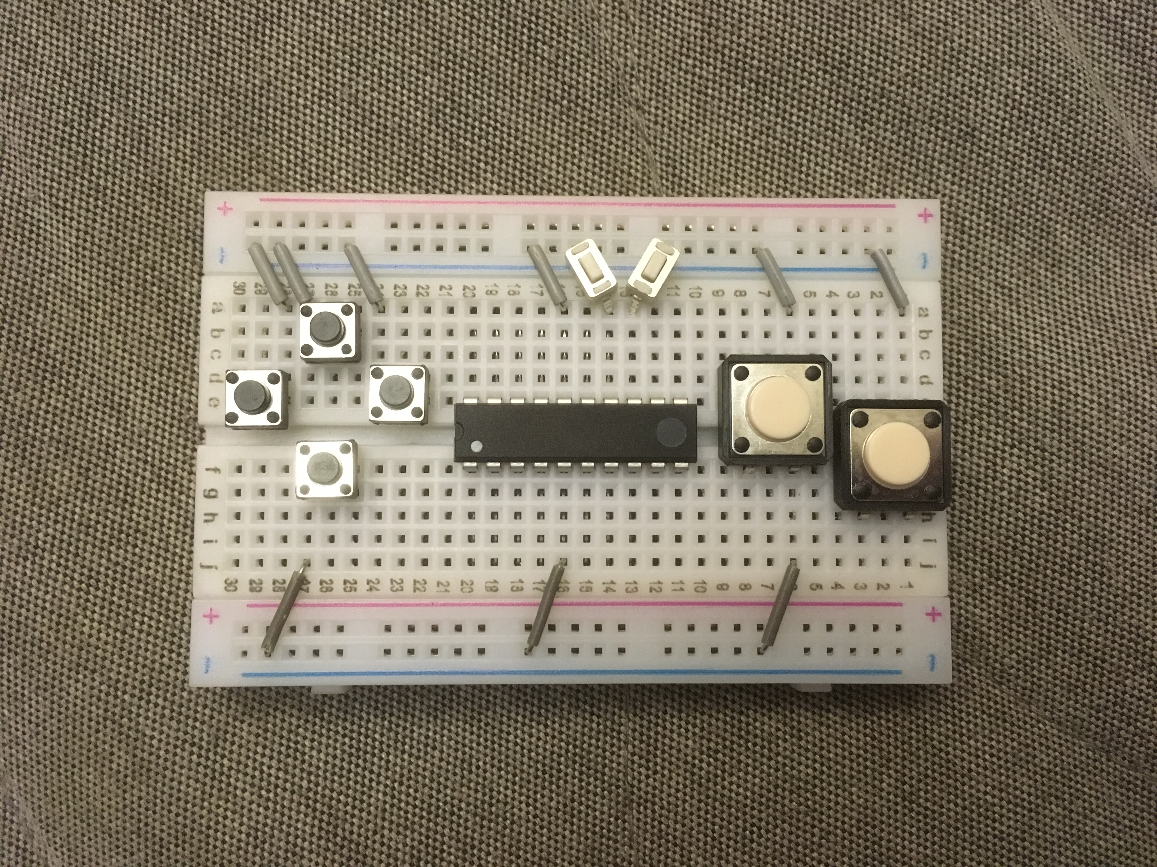
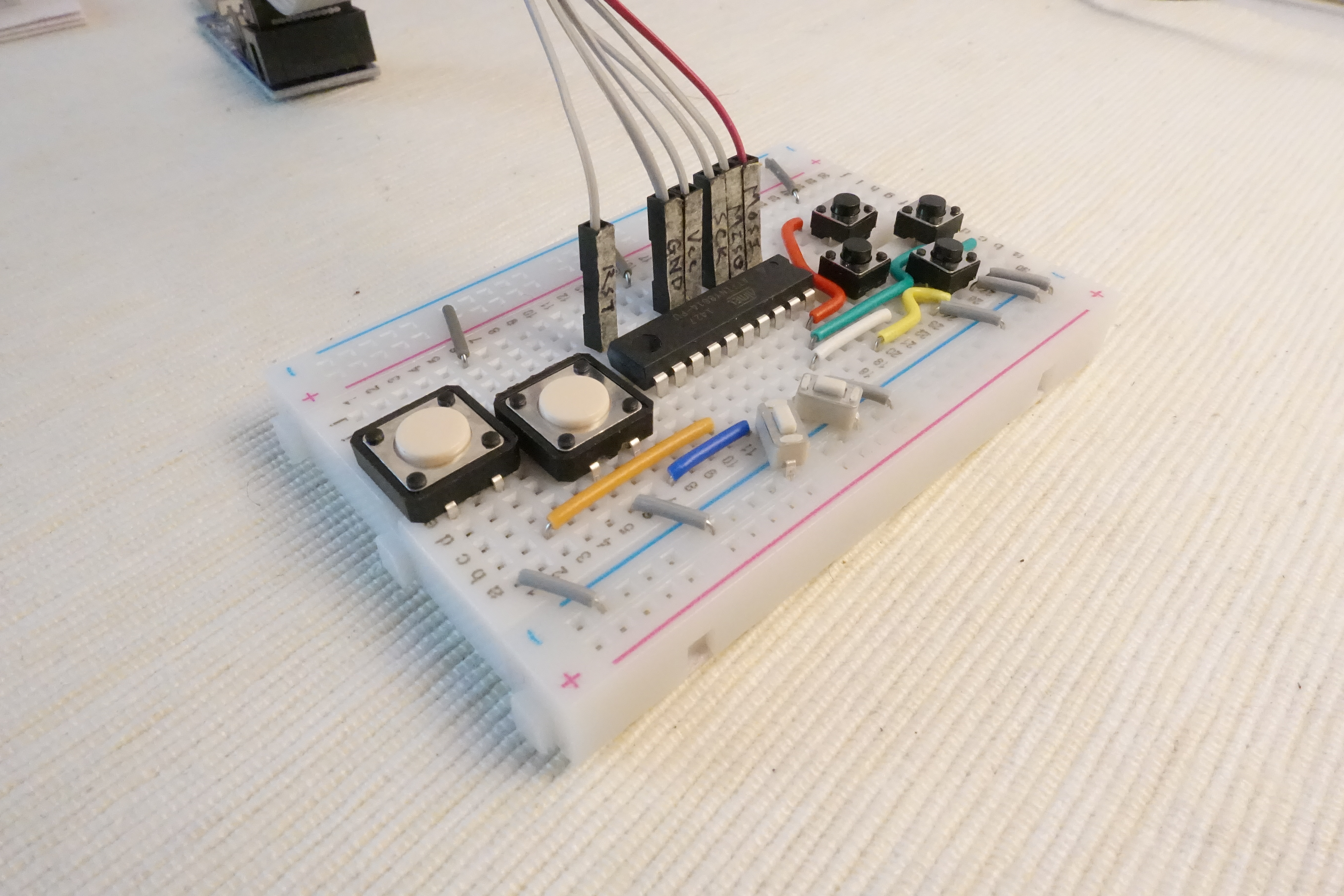
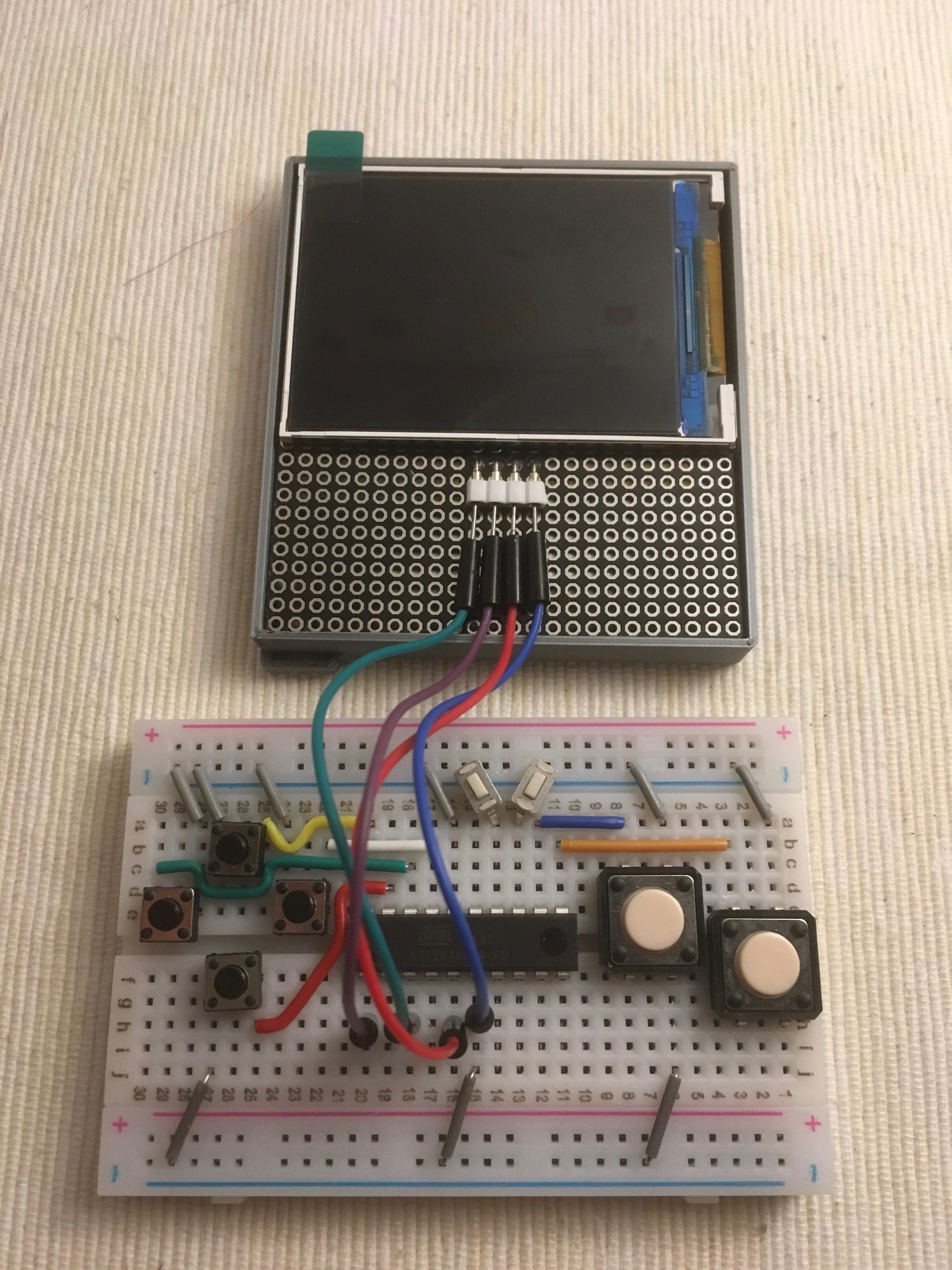
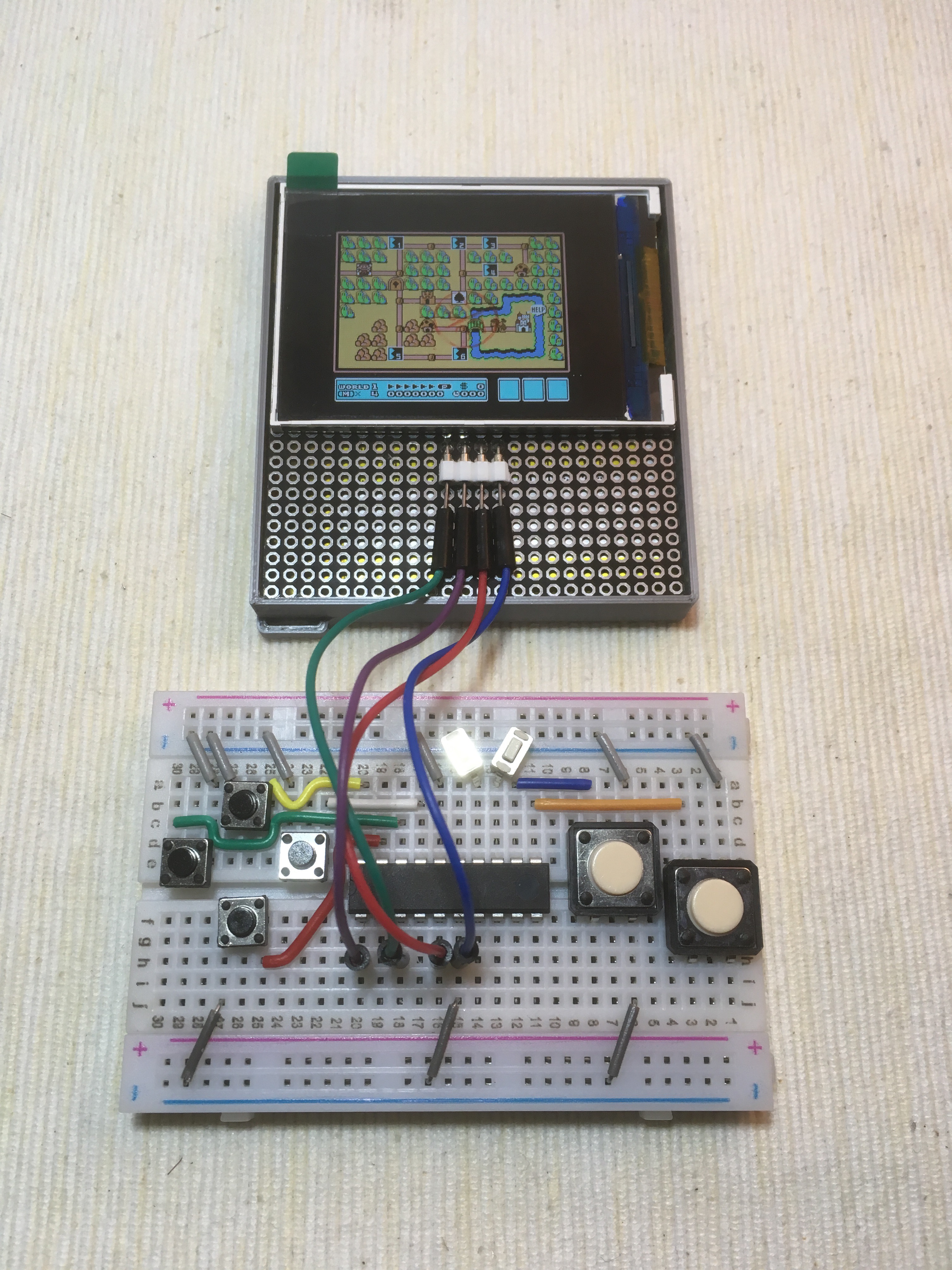
The program for the I2C Gamepad is very simple, only 15 lines of code. But it is a little bit hard to reprogram the ATtiny861 after soldering, so it is better test it on the breadboard first.
Download, compile and flash the program from GitHub: https://github.com/moononournation/attiny861_i2c_...
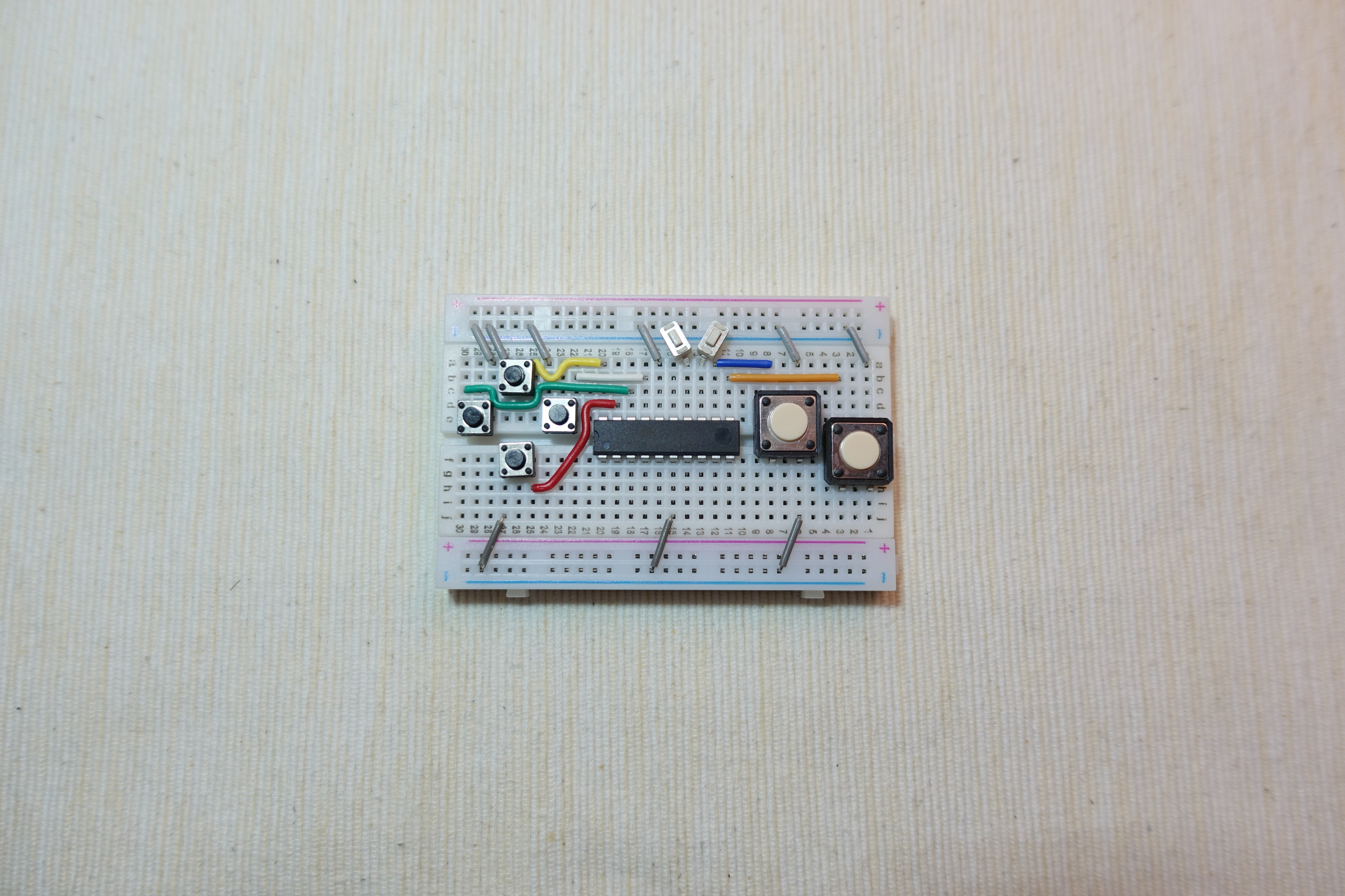
Build I2C Gamepad
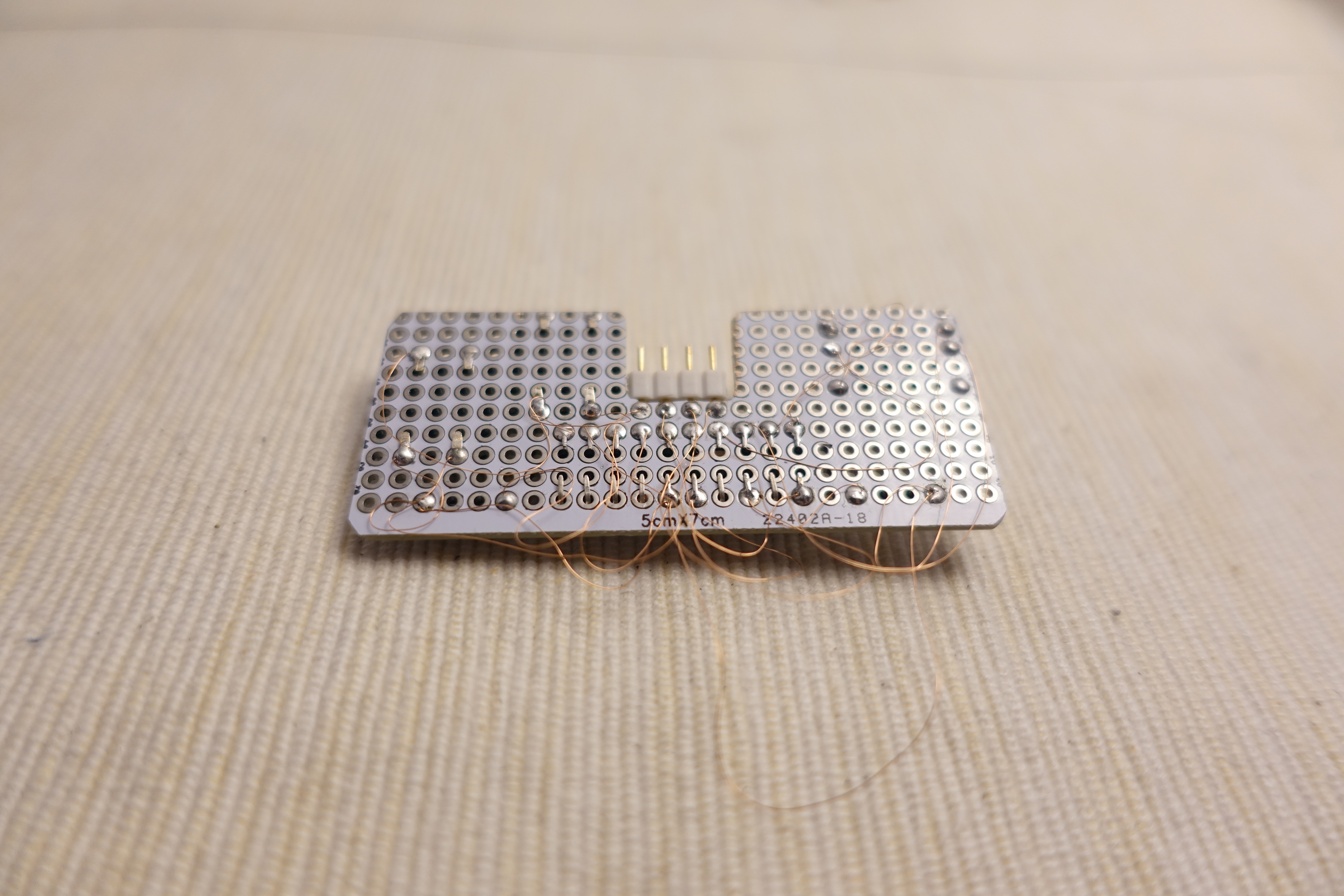
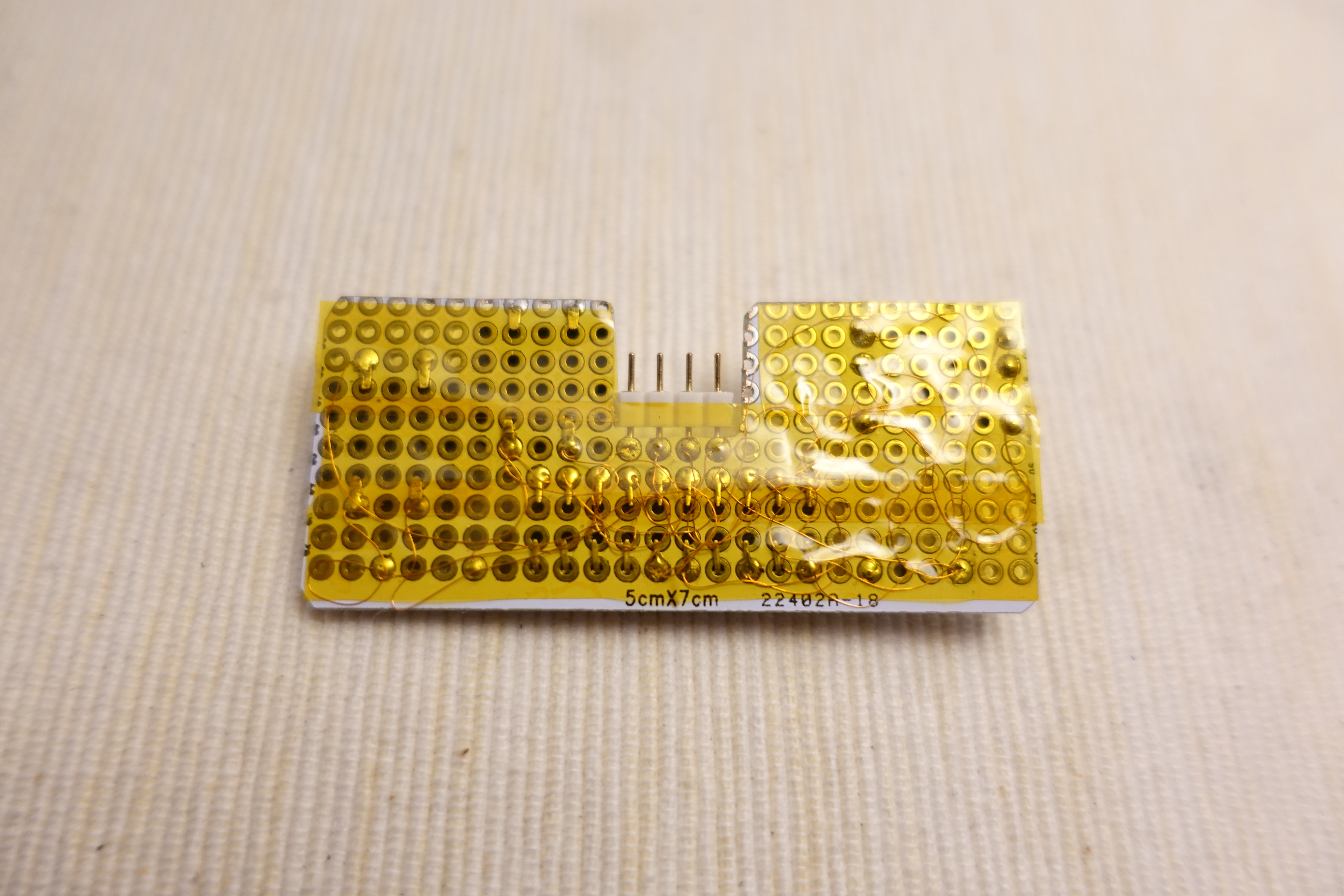

Here are the connection Summary:
ATtiny861       Button
GND          -> All buttons one pin
Pin 20 (PA0) -> Up button
Pin 19 (PA1) -> Down button
Pin 18 (PA2) -> Left button
Pin 17 (PA3) -> Right button
Pin 14 (PA4) -> Select button
Pin 13 (PA5) -> Start button
Pin 12 (PA6) -> A button
Pin 11 (PA7) -> B button
Pin 6 (GND) -> I2C male pin header pin 4
Pin 5 (Vcc) -> I2C male pin header pin 3
Pin 3 (SCL) -> I2C male pin header pin 1
Pin 1 (SDA) -> I2C male pin header pin 2
Assembly Part 2
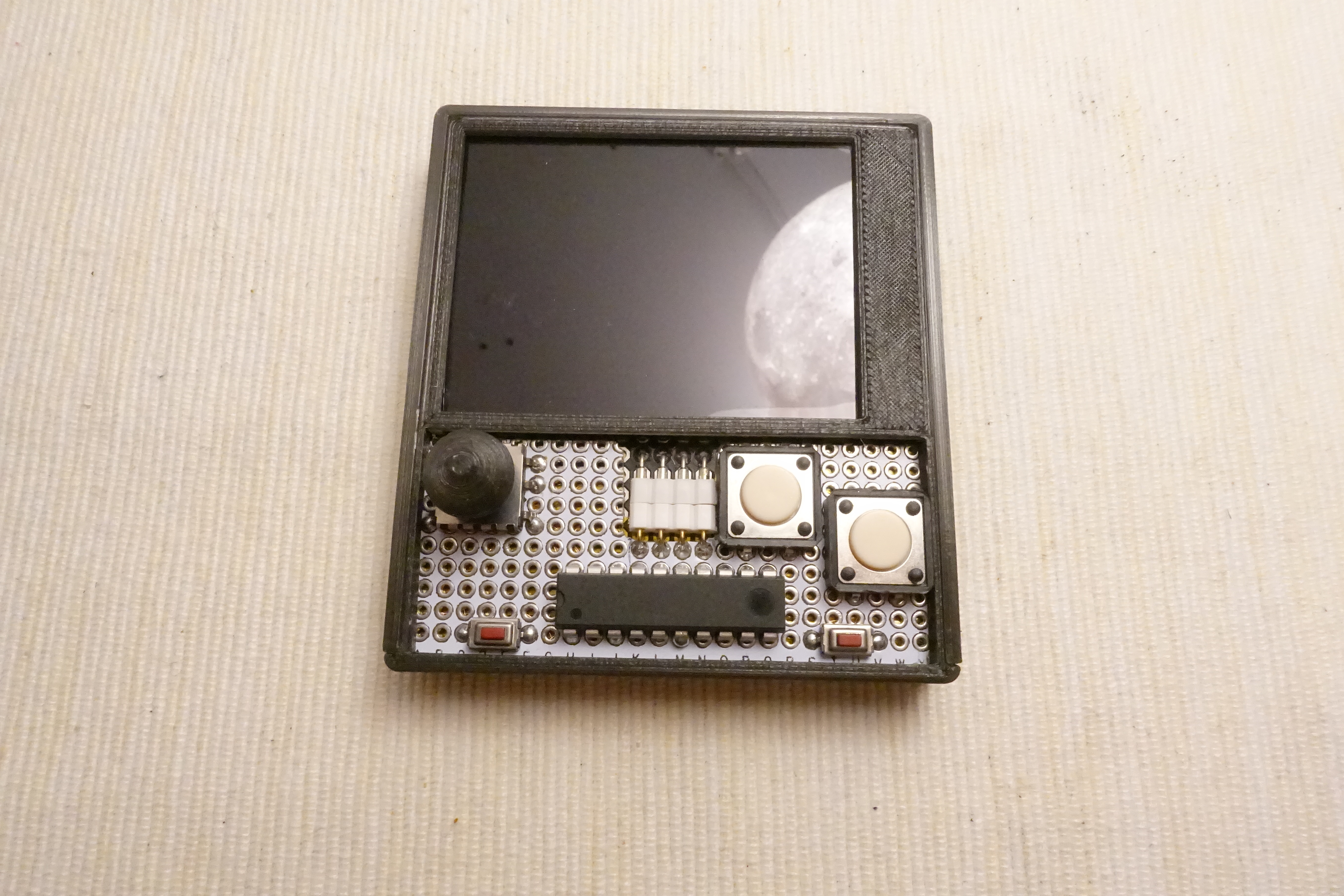
Follow the video steps to install the cover and the I2C gamepad to the main body.
Optional: Audio Breakout Pins
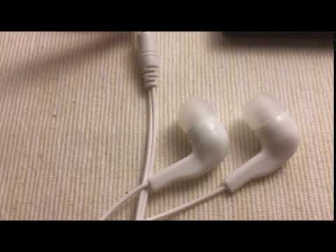
ESP32 dev board Pin 25 and 26 is outputting the analog audio signal, it is very easy to breakout the these 2 pins and also power pins (3.3 V and GND) on the top. Then you can patch a earphone to plug on it. Or even you can add an audio amplifier module with speaker to play it loud.
What's Next?
NES emulator is not the only interesting thing you can make with ESP32. E.g. you can build a micro python console with it. The only component you need to change is from I2C gamepad to I2C keyboard. I think it is not so difficult to make it with a ATtiny88 controller. You may follow my twitter to see the status.