ESP32 Device As a RS-485 Modbus Master | Norvi IIOT
by NORVI Controllers in Circuits > Microcontrollers
13305 Views, 5 Favorites, 0 Comments
ESP32 Device As a RS-485 Modbus Master | Norvi IIOT
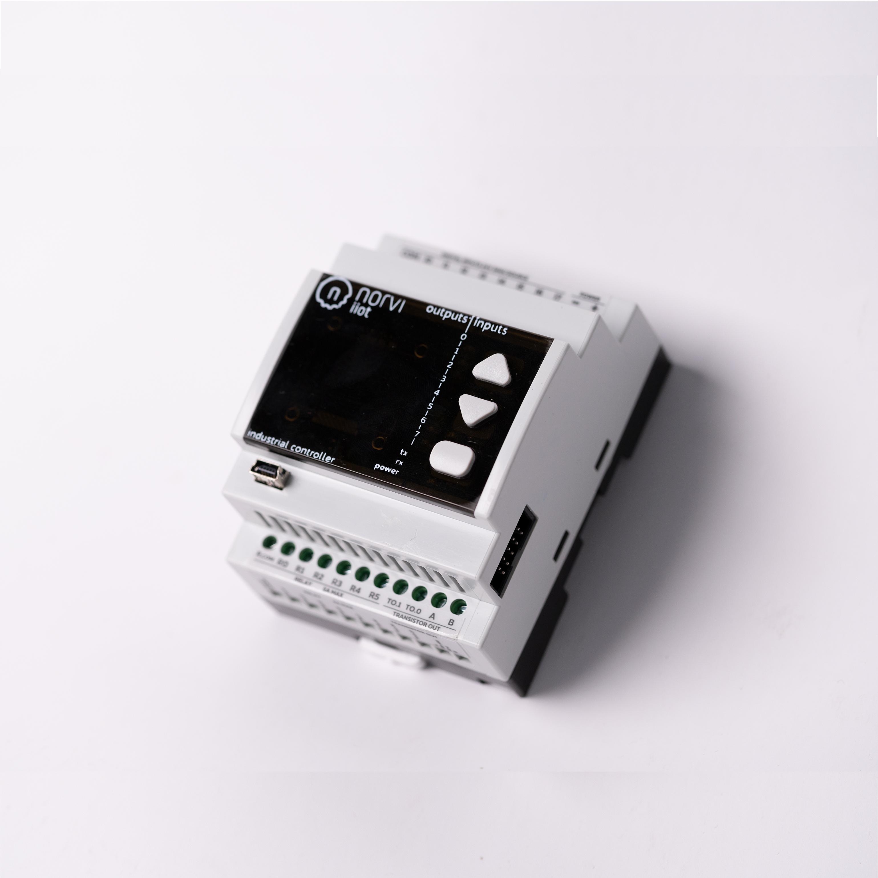
In this instructable, we'll be looking at how to read multiple digital inputs of an ESP32 based Industrial IoT Device Norvi IIOT-AE02-V, using Modbus protocol. Here, we'll be considering the simplest configuration, where the Norvi device will be the master and "Modbus Slave" software will be the slave.
Check out our previous instructable to understand the working of Modbus protocol. - https://www.instructables.com/ESP32-As-a-RS-485-Mo...
And check this tutorial to know more about how to work with Norvi IIOT-AE02-V. - https://www.instructables.com/Introduction-to-Norv...
The features of Norvi-IIOT-AE02-V are,
- 8 Digital Inputs 24V
- 6 Analog inputs (0-10V)
- 2 Transistor outputs, PWM compatible (36VDC max with 360mW collector power dissipation)
- RS-485 Communication
- WIFI & Bluetooth
- Built-in OLED Display with 3 buttons
- Expansion port with I2C, UART and GPIO
So what do you need to get started?
- The Norvi IIOT-AE02-V device. Check more about the product
- Wires for connection
- USB cable (Type A to Type B mini)
- USB to RS-485 Converter module
- PC/Laptop
- The Modbus slave Software
Understanding More About the RS-485 Connection
- The Device has a built-in MAX485 driver with RX connected with GPIO3, TX connected with GPIO1 and RE & DE are connected with the GPIO4 (for flow control) of the Norvi ESP32 device.
GPIOs of the Device
- Check steps 3 and 4 in this instructable.
Writing the Program
- Install the Modbus Master library in your Arduino IDE and upload the below sketch. (For installing the ESP32 board and booting up the device, check the steps 1 and 2 of our previous instructable - Getting Started With Norvi Devices)
#include <ModbusMaster.h>                             //Library for using ModbusMaster
#define FC 4                                          //RE & DE are connected with the GPIO4 (for flow control) of the Norvi ESP32 Device.
ModbusMaster node;                                    //object node for class ModbusMaster

void preTransmission()                                //Function for setting stste of Flow control pin of RS-485
{
  digitalWrite(FC, 1);
}

void postTransmission()
{
  digitalWrite(FC, 0);
}
void setup()
{
  pinMode(FC, OUTPUT);
  digitalWrite(FC, 0);
  Serial.begin(9600);                                //Baud Rate as 9600
  pinMode(18, INPUT);                                //Initialize the inputs and outputs
  pinMode(39, INPUT);
  pinMode(34, INPUT);
  pinMode(35, INPUT);
  pinMode(19, INPUT);
  pinMode(21, INPUT);
  pinMode(22, INPUT);
  pinMode(23, INPUT);
  node.begin(1, Serial);                              //Slave ID as 1
  node.preTransmission(preTransmission);              //Callback for configuring RS-485 Transreceiver correctly
  node.postTransmission(postTransmission);
}

void loop()
{
    node.writeSingleRegister(0x40000, digitalRead(18));             //Writes value to 0x40000 holding register

    node.writeSingleRegister(0x40001,digitalRead(39) );             //Writes value to 0x40001 holding register

    node.writeSingleRegister(0x40002, digitalRead(34));             //Writes value to 0x40002 holding register

    node.writeSingleRegister(0x40003, digitalRead(35));             //Writes value to 0x40003 holding register

    node.writeSingleRegister(0x40004, digitalRead(19));             //Writes value to 0x40004 holding register

    node.writeSingleRegister(0x40005, digitalRead(21));

    node.writeSingleRegister(0x40006, digitalRead(22));

    node.writeSingleRegister(0x40007, digitalRead(23));

    delay(1000);
}<br>
Circuit Connection and Modbus Slave Software Configuration
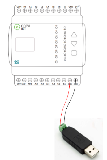
- Connect the MAX 485 driver's A & B pins with the A & B pins of USB to the RS-485 module.
- After the circuit connections are completed connect the USB to RS-485 Module to the PC where the Modbus Slave Software is installed.
- Open the "Connection" menu in the software and select the right com port & the baud rate.
- In the "Setup" ---> "Slave Definition" menu, make sure that the right "Slave ID" is selected & the "Function" is Holding register.
Understanding the Code
- We begin by adding the Modbus Master library.
#include <ModbusMaster.h>
- Next, the flow control pin for the RS-485 communication is defined.
#define FC 4
- Then the object node for Modbus master is named and the functions required for setting the state of the flow control pin are defined.
ModbusMaster node;                                    //object node for class ModbusMaster
void preTransmission()                                //Function for setting the state of Flow control pin of RS-485
{
  digitalWrite(FC, 1);
}
void postTransmission()
{
  digitalWrite(FC, 0);
}- Next, we define the Slave ID, inputs, and outputs of the device.
void setup()
{
  pinMode(FC, OUTPUT);
  digitalWrite(FC, 0);
  Serial.begin(9600);                                //Baud Rate as 9600
  pinMode(18, INPUT);                                //Initialize the inputs and outputs
  pinMode(39, INPUT);
  pinMode(34, INPUT);
  pinMode(35, INPUT);
  pinMode(19, INPUT);
  pinMode(21, INPUT);
  pinMode(22, INPUT);
  pinMode(23, INPUT);
  node.begin(1, Serial);                              //Slave ID as 1
  node.preTransmission(preTransmission);              //Callback for configuring RS-485 Transreceiver correctly
  node.postTransmission(postTransmission);
}- Finally, using the below code the status of the digital input pins is displayed in the Modbus Slave Software.
void loop()
{
    node.writeSingleRegister(0x40000, digitalRead(18));             //Writes value to 0x40000 holding register

    node.writeSingleRegister(0x40001,digitalRead(39) );             //Writes value to 0x40001 holding register

    node.writeSingleRegister(0x40002, digitalRead(34));             //Writes value to 0x40002 holding register

    node.writeSingleRegister(0x40003, digitalRead(35));             //Writes value to 0x40003 holding register

    node.writeSingleRegister(0x40004, digitalRead(19));             //Writes value to 0x40004 holding register

    node.writeSingleRegister(0x40005, digitalRead(21));

    node.writeSingleRegister(0x40006, digitalRead(22));

    node.writeSingleRegister(0x40007, digitalRead(23));

    delay(1000);
}
Understanding the Operation of the Modbus Slave Software
- Visit - https://www.modbustools.com
To check more about the Norvi lineup- - www.norvi.lk