ESP32 Controlled Storage Heater
by fotherby in Workshop > Energy
2799 Views, 4 Favorites, 0 Comments
ESP32 Controlled Storage Heater


I realise it looks like an enormous Christmas present… but it’s actually an ESP32 controlled storage heater. It stores 12kWh of off-peak electricity in a 300L tank of hot water. It releases this on demand during the day and saves me £100/month. I spent £400 building it. I hope this write up is interesting.
Motivation
With the rocketing prices of energy and a house only heated by electricity I looked for ways to save money on heating. I have signed up to an electricity company called Octopus which offers 4 hours of cheap electricity between 00:30-4:30. I live in England, during these hours electricity costs me 7.5 p/kWh compared to 40 p/kWh otherwise (contract Sept-22 - Sept-23). That is a HUGE difference and needs to be taken advantage of.
Our dishwasher, washing machine, immersion heater, EV charger, towel rails all come on at night but our heating was the weak link. Storage heaters are designed to take advantage of price differences. However most storage heaters are rubbish because the heat released follows an exponential decay. That is, most heat is released straight after they are charged up in the morning. Little heat is left to release by the time the evening comes.
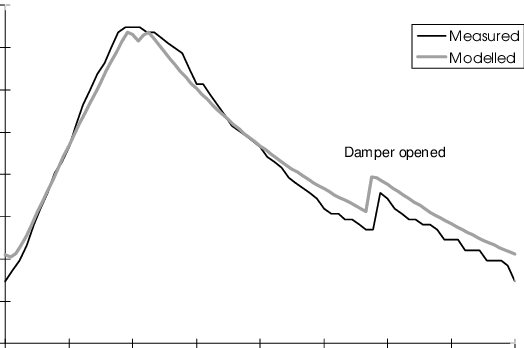
This graph shows the heat released by an ordinary storage heater over a 24hr period. You can see that most of the heat is released just before and after it’s “charged”. Not much heat is available at the end of the day.
This compares against the storage heater described here which releases no heat during the charge up phase and a constant heat output during the day only when required. I shall explain how it all works.
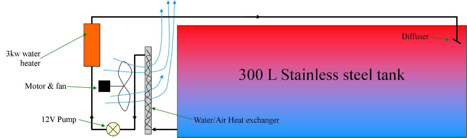
System Diagram
Tank Choice
I found a 300L stainless steel fuel tank on Facebook Marketplace and went to collect it from an old chap in Southend-on-Sea. He’d had it lying in his garage for 40 years and had finally decided to sell it for £250.
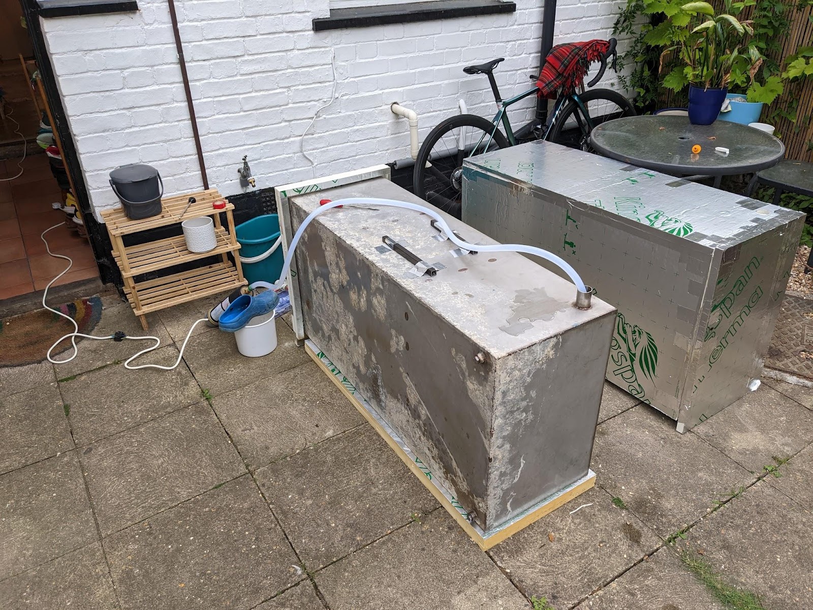
Thanks to the enormous specific heat capacity of water, 300L of water changing temperature by 35℃ transfers 12kWh of heat. I was thinking of operating between about 80 and 45℃. The tank was in good condition thanks to being made of stainless steel. I considered plastic tanks (they’re much cheaper) but I couldn’t find any that could work above 60℃. A steel tank might work but I was concerned about rusting.
Estimating Standing Losses
I have surrounded the tank (Dimensions 1.2m x 0.42m x 0.6m) with 25mm Kingspan insulation and I sat the tank on a 50 mm panel of insulation.
The Kingspan insulation has a thermal conductivity of 0.022 W/mK. We can therefore estimate the expected heat loss from the tank at various temperatures. The total area of the insulation is 1.2x0.6x2 m² + 1.2x0.4x2 m² + 0.4x0.6x2 m² = 2.88 m².
We can ignore losses from the base of the tank because 1) The water temperature will stratify, 2) I have put 50 mm of insulation on the base. So let's take our area to be 2.4m².
The thermal conductivity of 25mm insulation will be 0.88 W/k. Therefore with the tank at 70℃ and the room at 20℃ we can expect approximately 0.88 x 2.4 x 50 = 105 W of standing heat loss. This will be an overestimation because I have added further insulation in the form of a fabric cover for aesthetics and the air surrounding the tank won’t conduct the heat away well.
100 W of standing losses is brilliant, it means it’d take well over 240 hours (10 days) to lose 12kWh of heat by itself. We want the standing losses to be low because we want to actively release the heat when required.
Heat up phase

During the heating phase water is pumped through a 3kW willis heater. The water is drawn from the bottom of the tank, pumped into the heater and returns to the top of the tank. We modulate the speed of the pump so that the existing water from the heater is at 80℃. This hot water stratifies in the top of the tank so the pump sucks in the coldest water. To help prevent mixing and to improve stratification I put a T fitting on the end of the return pipe. This sits in the top of the tank and I figured it would reduce the amount of stirring that’d be caused by diverting the hot water flow sideways rather than downwards.


Heat release phase
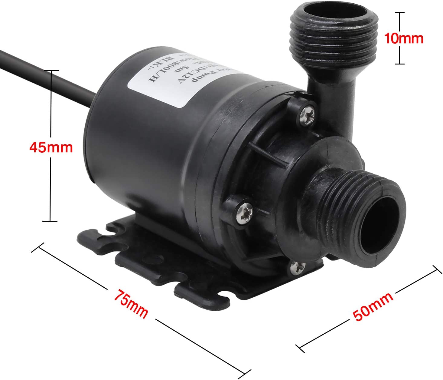
To release the heat the pump turns on together with some fans. The water is pulled through a water-air heat exchanger and the heat is blown off by the fans. The water is cooled before it reaches the pump to avoid exposing it to high temperatures. The pump is 12V and from Amazon. I’ve been really impressed by the longevity of these sorts of brushless pumps but nevertheless I wanted to minimise any stresses put on it.
The heating water is drawn from the bottom of the tank into the exchanger. This is not ideal but works fine because of mixing. The cooled water is discharged into the hot stratified layer at the top of the tank. This mixes the tank very effectively so that it becomes 1 uniform temperature. Very quickly the water exiting the bottom is just as hot as the water at the top of the tank.

If we drew hot water from the top of the tank and returned cold water to the bottom we could maintain the stratification. The benefit would be when it comes to releasing the heat via the exchanger. You could have very slow water flows through the heat exchanger and still discharge lots of heat if the entering water was at 80℃. This would reduce pumping speeds and the associated noise and allow for higher peak heat outputs if desired. But it would complicate the system.
Heat release calculations
I’m still developing my intuitions on heat loss rates. (I always underestimate how easy it’ll be to cool things). In this project I thought I’d attempt some calculations before cocking up. I found an aluminium heat exchanger on Amazon with dimensions 25x30cm.

I needed to know what sort of air flow rates would be needed through this heat exchanger. Engineering toolbox has an excellent page on HVAC heating which provides all the figures and equations needed. I needed a heat output of about 750W. (To release 12kWh over 16 hours). With the heat exchanger warming the air by 20℃ an airflow of 112m^3/hr was required.
From browsing the internet I discovered 12cm computer fans blew approximately 40-60m^3/hr. This could vary too, depending on the voltage supplied to them. I realised I could use 2 fans in parallel to obtain the needed airflow.
If 50℃ water is passing through the exchanger, at what temperature would the air exit at? I guessed about 40℃ depending on the airflow speed. Hence for a 20℃ rise in air temperature we’d need water flowing through the heat exchanger about 30℃ hotter than the air intake temperature. Assuming an air input of 17℃ the minimum water flow temperature that’d allow for 750W of heating would be 47℃, call it 50℃.
If the tank is hotter than 50℃ that’s no problem, we can reduce the flow of water through the heat exchanger to maintain an air temperature differential of 20℃. If we have a constant airflow and a constant air temperature differential then the heat output power will also be constant. That’s quite nice!
Centrifugal pumps obey a few general rules. One of these rules is that the flow rate is proportional to the pump speed. The speed of a motor is proportional to its voltage. Therefore the flow rate is proportional to the voltage applied to the pump. Sweet!
So we can reduce the water flow by reducing the voltage to the 12V pump. It still operates fine at 6V. If you still need to reduce the water flow rate then the pump can be turned on/off intermittently and you can vary the on/off time ratio (ie. the duty cycle). This allows us to reduce the average flow rate continuously all the way to zero if desired.
Electronics
I used an ESP32 microcontroller. The responsibilities of it being:
- Get the time from the internet using the NTP
- During off-peak hours turn on the heater and regulate the pump speed to produce 80℃ water for the tank.
- When heat is to be released, turn on the fans and control the pump speed to maintain an air temperature differential of 20℃.
- Log metrics to a local InfluxDB database - for my own amusement…

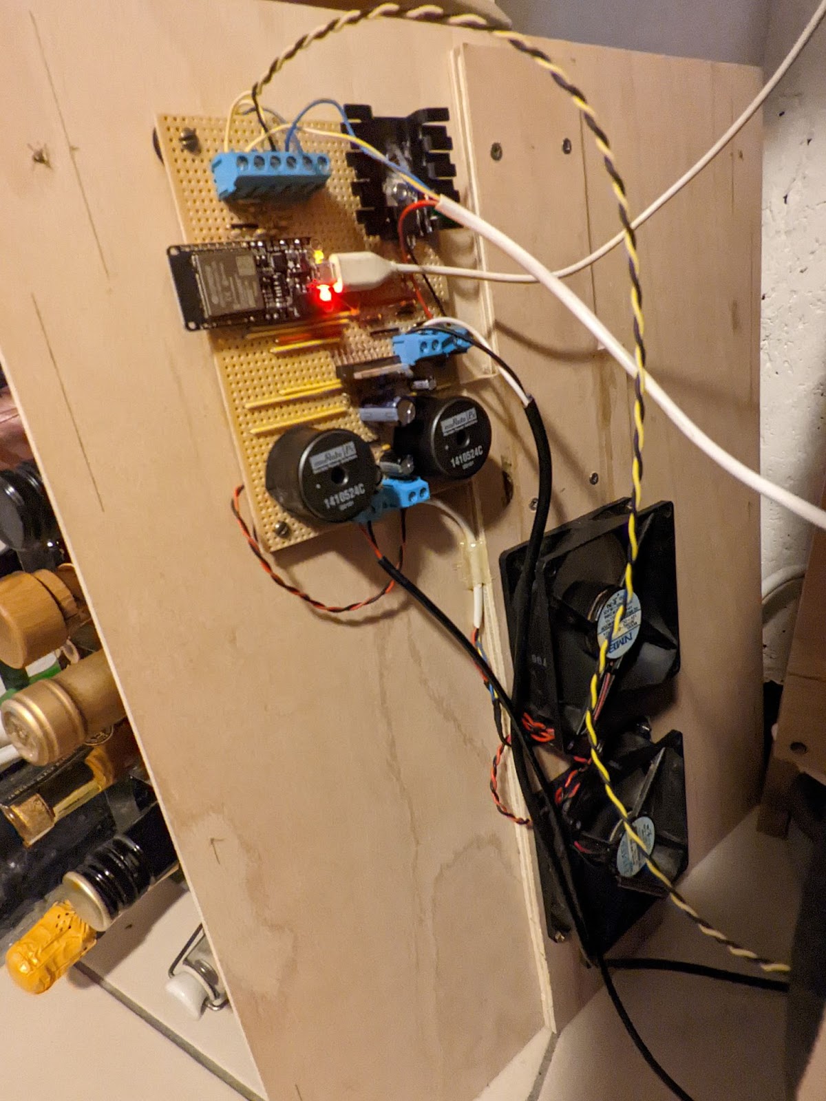
I used an L298N chip. This houses 2 H-Bridges or equivalently 4 half-bridges. I wired up 2 buck converters so that we could control the speed of our pump and fans independently by varying the PWM duty cycle.
I used a 19V laptop power supply to provide our DC voltage supply. This feeds directly to the buck converters. A 7805 linear regulator provides the 5V supply for the ESP32 and the logic to the L298N. It has a large heat sink because dropping 19V to 5V is quite a big jump and the ESP can supposedly draw 250mA when using its WiFi.
There are 3 temp sensors. One is in the air intake right behind the fan. One is in the Air outlet stream after the heat exchanger and the 3rd is under some insulation on top of the water heater against its metal enclosure. They are all 10K thermistors. I used a 4.7K pull-up resistor for the water temp thermistor because at the sort of temperatures it will operate at, a 4.7K pull-up resistor will improve the gradient of voltage vs temperature.

Software
It’s all available here on GitHub. Nothing particularly clever.
Tests
I have a Raspberry Pi server at home which runs InfluxDB (A time series database) and Grafana (To display the data). I used some ESP32 libraries to log various metrics and plot these. Here’s a 24 hour period, let’s talk it through:
00:30 - Heating phase commences. The 3kW heater and pump turns on. The orange line represents the water return temperature and goes to 80℃. The blue line is the pump speed and remains fairly constant for 3.5hours. This implies the water drawn from the bottom is staying at the same temperature during this period so the hot water entering the top must be stratifying. In the last 30 minutes the flow rate creeps up a little presumably because the growing hot water layer is beginning to reach the bottom of the tank. As such the temperature drawn from the bottom begins to rise and so the flow rate through the heater must increase in order to maintain a 80℃ return temp. This is also evidenced by the yellow line which shows the heated air temperature. During the heat up phase I run the fans very slowly to a) keep the enclosure and electronics cool and b) so the air temperature offers a proxy for the inlet water temperature. Sure enough you can see this air temperature rise which can only be because of a rising water inlet temperature.
04:30 - We sleep. Fans, pump and heater all suddenly turn off. You can see the blue-flow rate go to zero. I believe that the orange return temperature stays elevated due to convection. I think the water flow reverses through the system very slowly so the heater unit stays full of hot water - interesting.

06:00 - We start our heat release phase. The pump speed is regulated in order to raise the intake air by 17.5℃. You can see this is happening very nicely as the difference between the yellow and green lines remains constant (green is air intake temp). You can see towards the end of the day the flow rate creeps up to maintain heat release and compensate for the falling average tank temperature.
At about 22:30 we limit the pump speed from going any faster and accept defeat. The tank has released its heat. We do a further 1 hour at a moderate pump speed just… because we can. After this hour we switch everything off ready for the heat up phase.
And the cycle repeats day after day.
Conclusions
It works well. It stores 12kWh of heat each night and releases all this over the next 16 hours. Therefore it must be releasing 750W during this time which is a decent heat source. It’s been running for about 2 weeks so far with no hiccups. I settled on a 17.5℃ setpoint for the air input-output differential as this made the unit last 16 hours. We can therefore calculate the airflow that must be moving through the system by our two 12cm computer fans => 35 l/s or 128m^3/hr. Nice!
- Time will tell how long the pump will last - I’m hoping, years. Easy and cheap to replace if it doesn’t
- I wish it stored more heat, perhaps the water could be heated to 95℃ (although the water heater might start being noisy as the water boils locally around the elements). I think it would be tricky to extract the heat from any water below 45℃. It would require quite high airflows. I think a second 3kW water heater would risk overloading the 32A circuit powering the unit because I also have a washing machine and dishwasher on the circuit.
- Initially I mounted the 12V pump to the inside of the enclosure. Even though it runs quietly on its own, when mounted, the enclosure was amplifying vibrations, making a noise. So I have just rested the pump on a towel instead.
- I suppose I could work on making the heater more intelligent - so it only turns on if someone is home etc
As always, I'd be interested to read your comments

Here's a video talking through the electronics.