ESP32 Basic PC With VGA Output
by Rob Cai in Circuits > Arduino
76691 Views, 95 Favorites, 0 Comments
ESP32 Basic PC With VGA Output
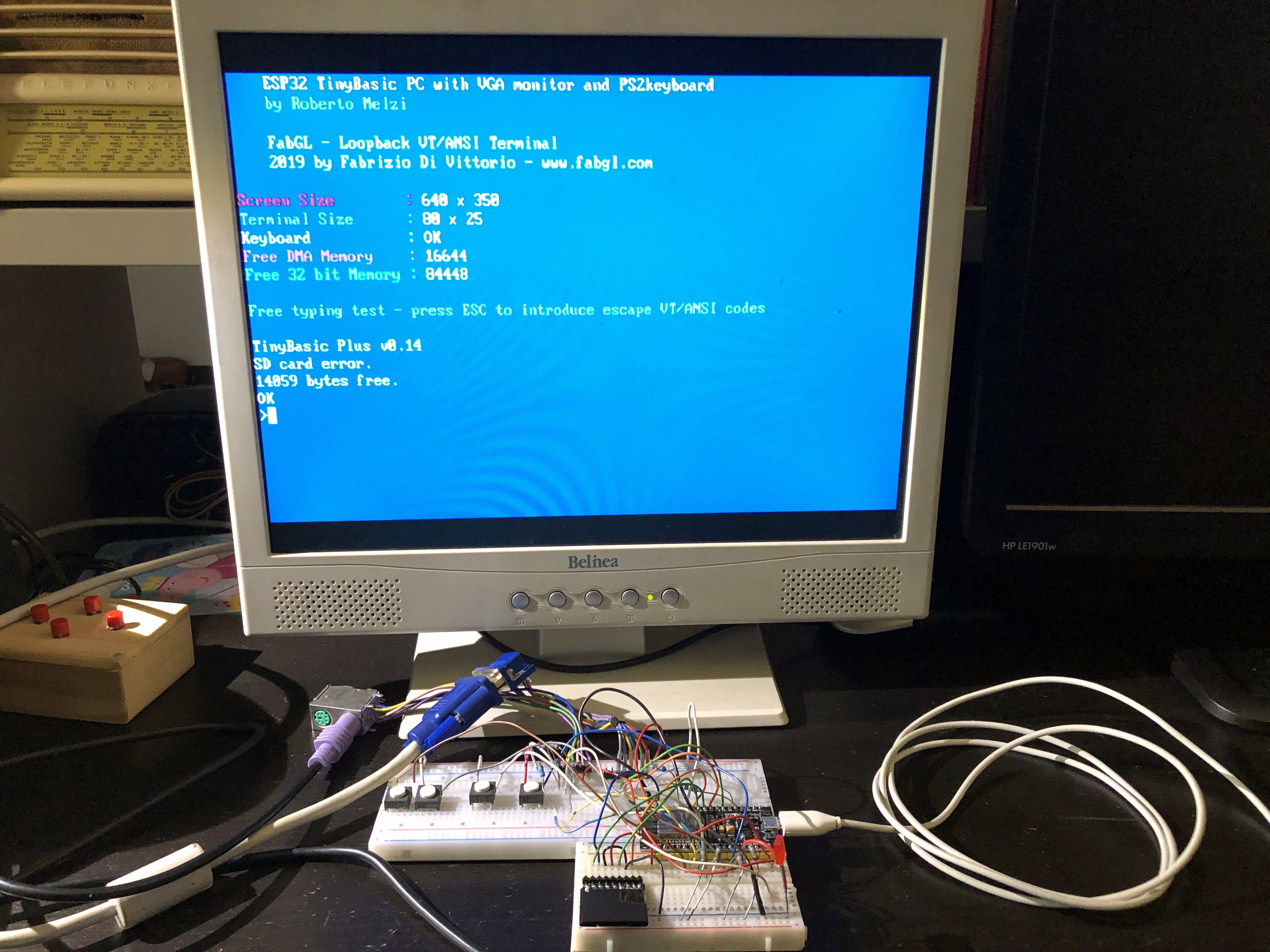
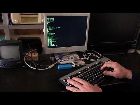
In this Instructable I am going to show how to build a simple retro style PC done with a single ESP32 and few other components.
This PC runs Tiny Basic, a simplified dialect of BASIC, and generates the output for a VGA monitor.
The resolution is 640x350 pixels, allowing 80x25 asci characters in 8 colors. A PS2 keyboards can be connected and used to write the code, allowing up to 14059 bytes of memory.
The ESP32 I/O pins can be directly driven by dedicated BASIC commands.
This project is made possible by the awesome ESP32 VGA library written by Fabrizio Di Vittorio. See here for more details.
ESP32 Boards, Arduino IDE Installation and VGA Library Configuration.
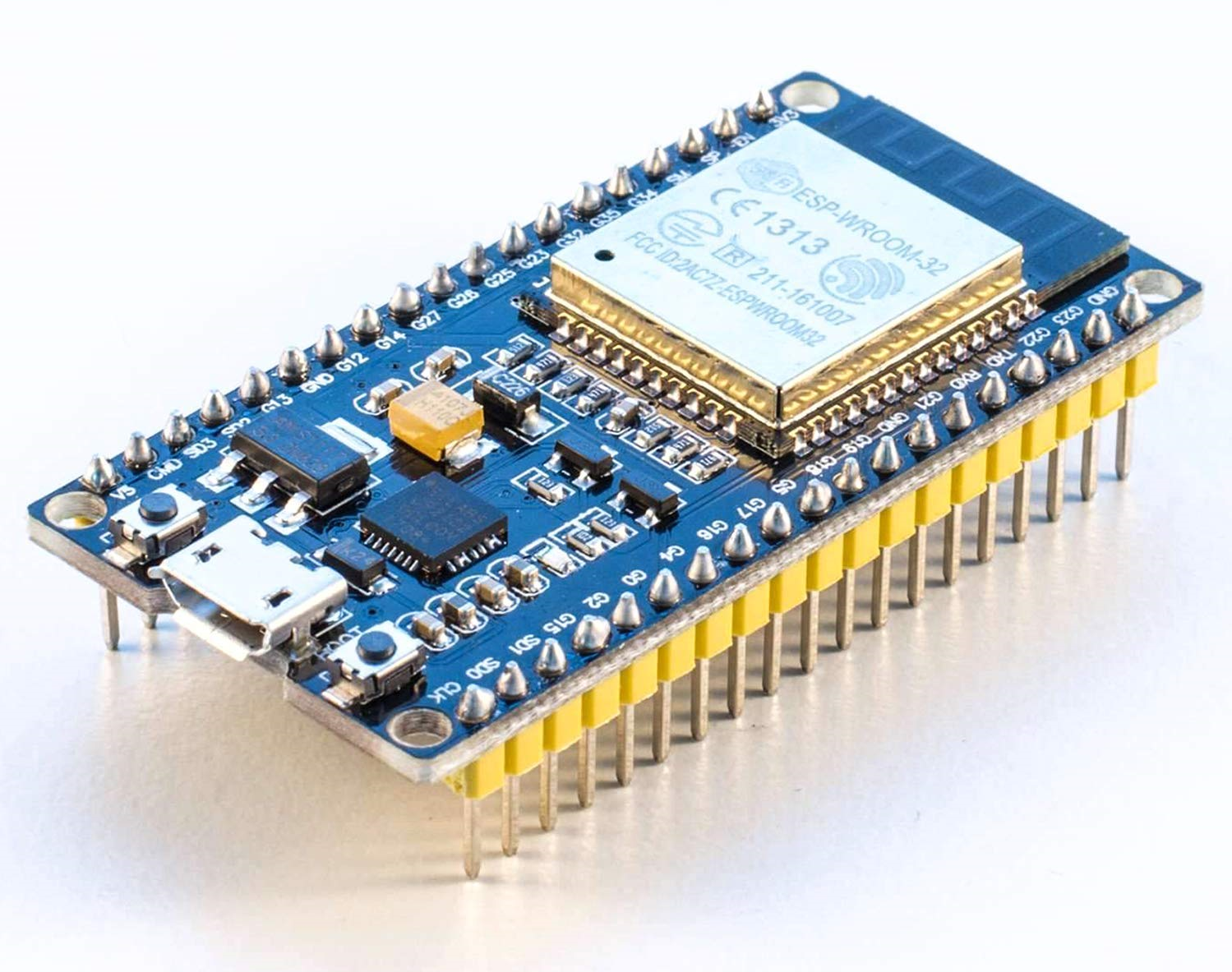
First of all you need to purchase an ESP32 revision 1 or upper. There are many versions available, but I recommend to choose one with many pins. I am using this version, but I think many other are fine too. For instance, in the description of this video, you can find three other models which are below 5 bucks.
Once you get the board, you need to proceed with the following three sub-steps:
- Install the last Arduino IDE
- Configure the ESP32 in the IDE and
- Install the VGA library
Sub-step 1.
There are different methods to program the ESP32, but here you need to use the latest Arduino IDE (I am using the version 1.8.9). To install it, you can go to the Arduino IDE page and follow the instruction.
Sub-step 2.
Once the previous operation is done, you need to configure your ESP32 within the Arduino IDE. This is not trivial, since the ESP32 is not (yet?) native in it. You can follow this tutorial, or the following steps.
1) open the Arduino IDE
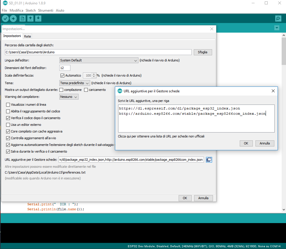
2) open the preferences window, File/Preference, alternatively press "Ctrl+comma"
3) go to the “Additional Board Manager URLs”, copy and paste the following text:
https://dl.espressif.com/dl/package_esp32_index.json
and click the OK button .
4) Open boards manager. Go to Tools/Board/Boards Manager…
5) Search for ESP32 and press the install button for the “ESP32 by Espressif Systems“:
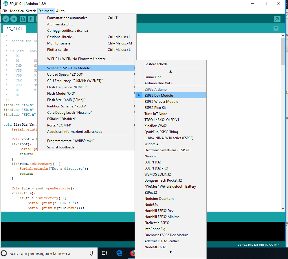
6) At this point, when you connect for the first time your ESP32, you should choose the right model in the long list of available ESP32 boards (see the picture in this step). In case of doubts about the model, just choose the generic one, i.e. the first one. It works for me.
7) the system should also choose the right USB port and the Upload Speed (normally 921600). At this point the connection between your PC and the ESP32 board should be established.
Sub-step 3.
Finally you have to install the FabGL VGA library. [update July 2019] You need and old version of this libray: you can download the zip file src.old.zip at the bottom of this step, uncompress and rename the folder as "src" in your
"...\arduino-1.8.9\libraries" folder.
Once you have done these operations, you can go to the next step and upload the modified TinyBasic following the next step.
Downloads
Uploading Tiny Basic Code to the ESP32
Download ESP32_TinyBasicPlus_PS2_FabLab_beta.ino at the bottom of this step.
Open it with the Arduino IDE and upload it to your raw ESP32.
If you have no error messages, the code should already be running.
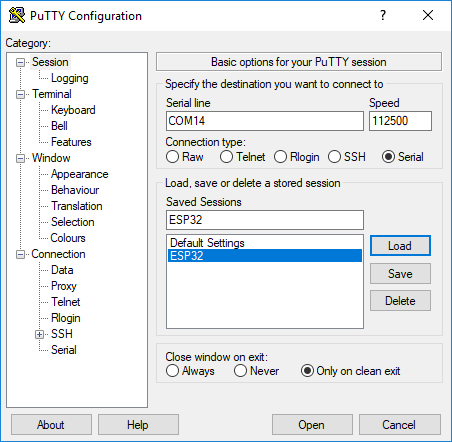
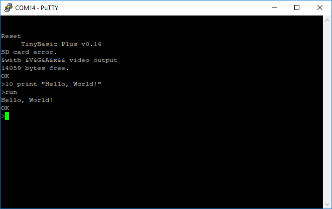
Facultative step: if you want to test TinyBasic before connecting the VGA and PS2 keyboard, you can already do it with a SSH and telnet client. I use PuTTY.
You can see how it looks in the pictures in this step.
Downloads
Connecting the VGA Port
You need the following parts:
- a DSUB15 Connector, i.e. a VGA female connector or a VGA cable to be cut.
- three 270 Ohm resistors.
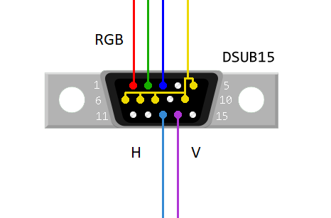
Connect the ESP32 GPIO pin 2, 15 and 21 to VGA Red, Green and Blue respectively, through the 270 Ohm resistors.
Connect the VGA Hsync and Vsync to ESP32 GPIO pins 17 and 4 respectively.
Connect the DSUB15 connectors pins 5, 6, 7, 8 and 10 to ESP32 GND.
For the VGA DSUB15 connector pin definition, see the picture in this step. NB, this is the soldering side of the female connector.
Connecting the PS2 Port
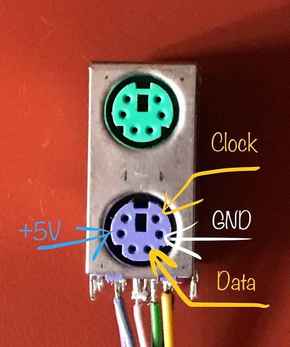
You need a PS2 keyboard female connector.
You can get one from an old PC motherboard, simply unsold it with a heat gun.
In the picture shown in this step, you can find the function of the needed pins of the PS2 connector.
The connection are:
- Keyboard Data to ESP32 GPIO pin 32
- Keyboard IRQ (clock) to ESP32 GPIO pin 33
- You also need to connect the 5V pin and the GND one.
Programming With Tiny Basic
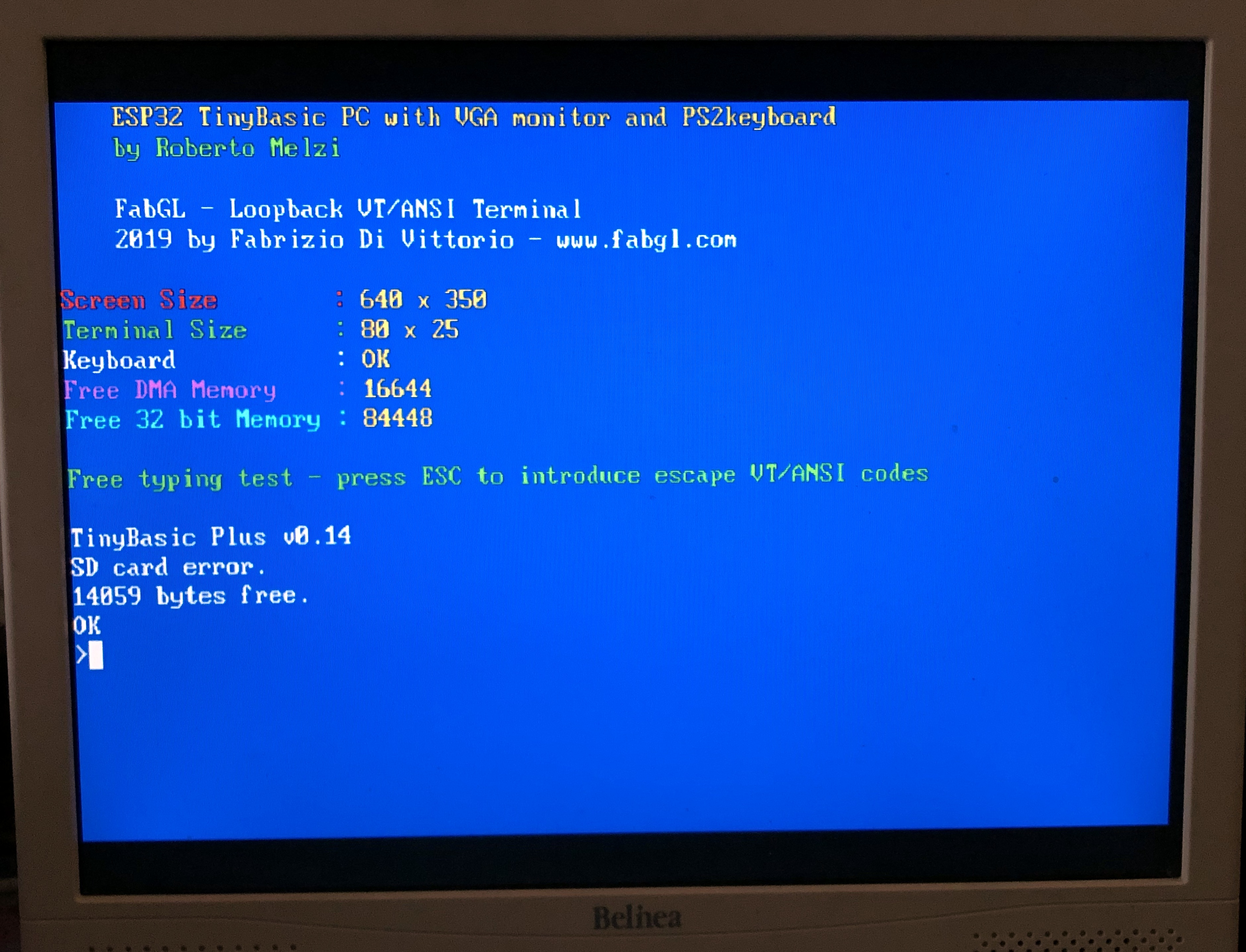
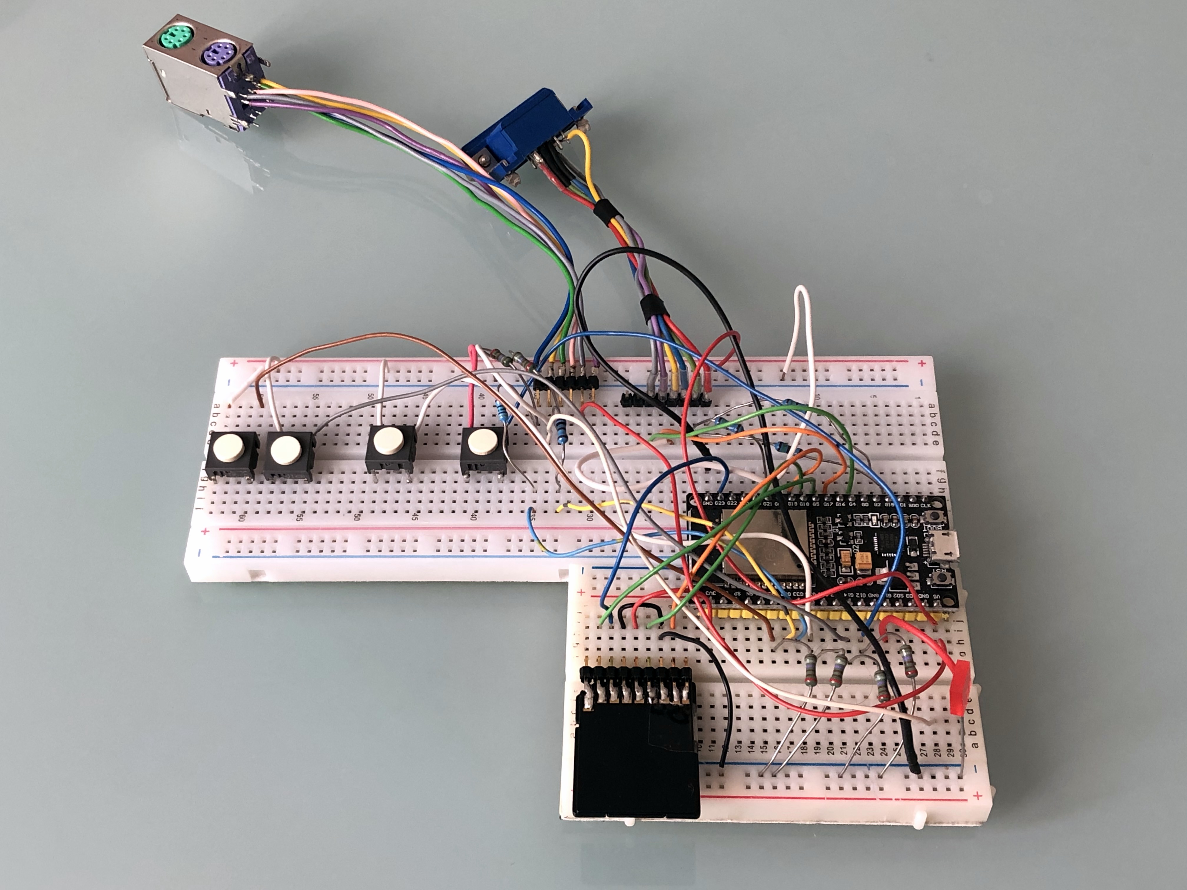
At this point, if you can connect the VGA monitor and PS2 keyboard and the ESP32 to power supply.
The image shown here should appear on the monitor. Now you can play a bit with Tiny Basic commands.
Try, for instance, the mandatory Hello, Word! infinite loop:
10 print "Hello, World!"
20 goto 10
run
You can change in four different colors pressing the esc button, and stop the loop with ctrl+c
Note that if you make a typo, you cannot cancel it! Or better, you can cancel but then the typo correction is not recognized. You need to rewrite the whole command line.
Now you can try something more complex, such as driving the blinking of an LED with a basic program. Connect, for instance, the LED anode (the long leg) to ESP32 GPIO pin 13, and the cathode to GND.
Then write:
new
10 i=1000
20 print i
30 delay i
40 dwrite 13,high
50 delay i
60 dwrite 13,low
70 i=i*9/10
80 if i>0 goto 20
90 end
run
You can see the result in the video embedded in this Instructable.
Connecting an SD Memory Card.
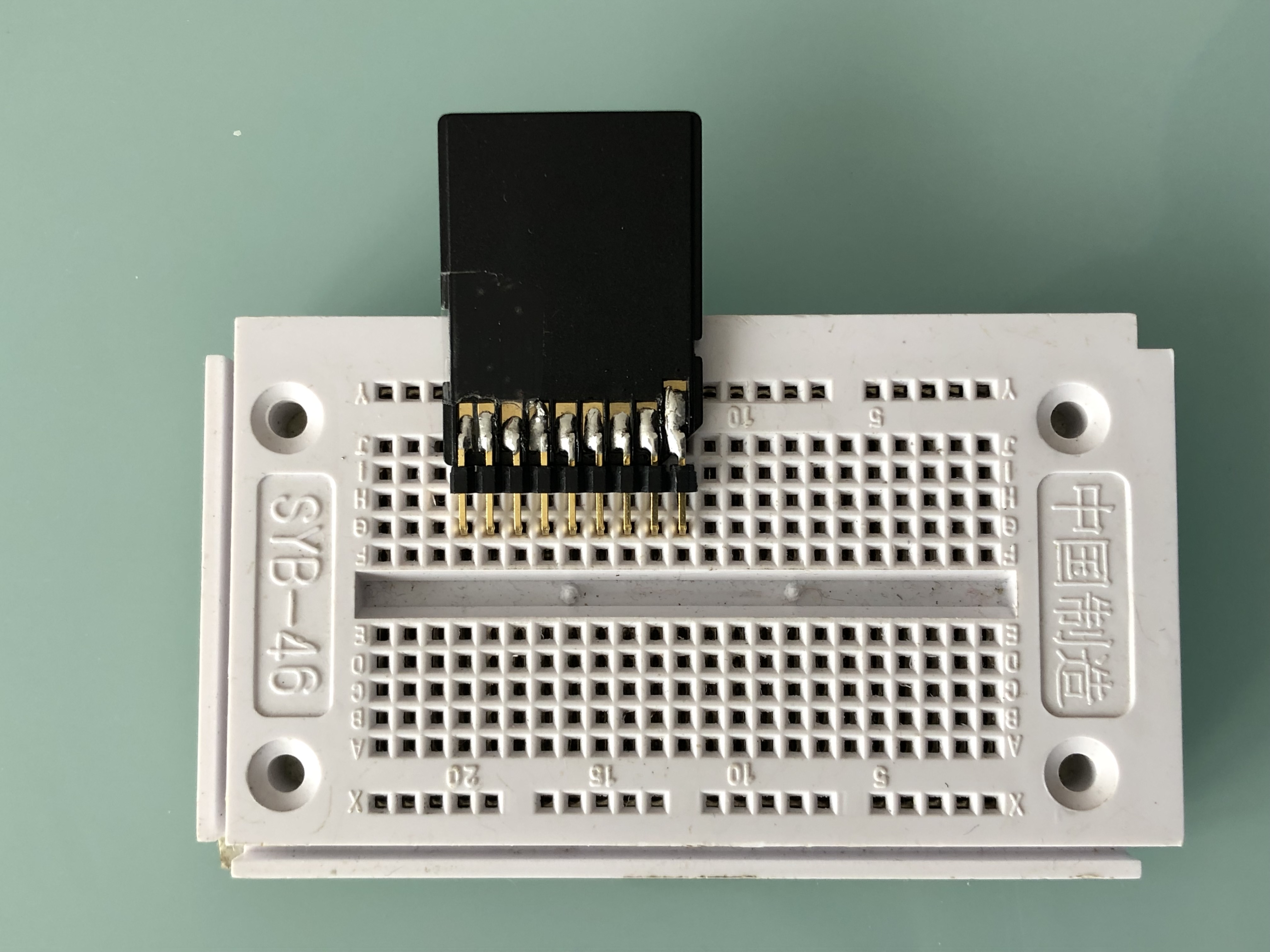
A vintage PC, it dos not matter how little and weak, cannot be complete if you cannot store your programs permanently.
In this step I will show how to connect a SD memory card, but unfortunately, for the moment (I hope only for the moment), the storing of programs does not work!
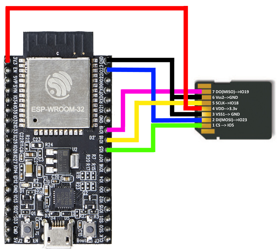
BTW, I used a microSD to SD card adapter and I soldered 8 L-shaped pins as shown in the picture in this step.
I then connected the SD adapters pins to the ESP32 according to he second picture, i.e. I connected the ESP32 GPIO pins 5, 18, 19, 23 to SC, clock, MISO, MOSO respectively, plus 3.3V and two GND.
I also followed the instructions and examples found here, and with the example code SD_test.ino, I can write on my 2 GBytes microSD card.
Thus if anybody find a solution, please inform me asap to my email rocaj74@gmail.com and I will complete this Instructable.
Acknowledgments
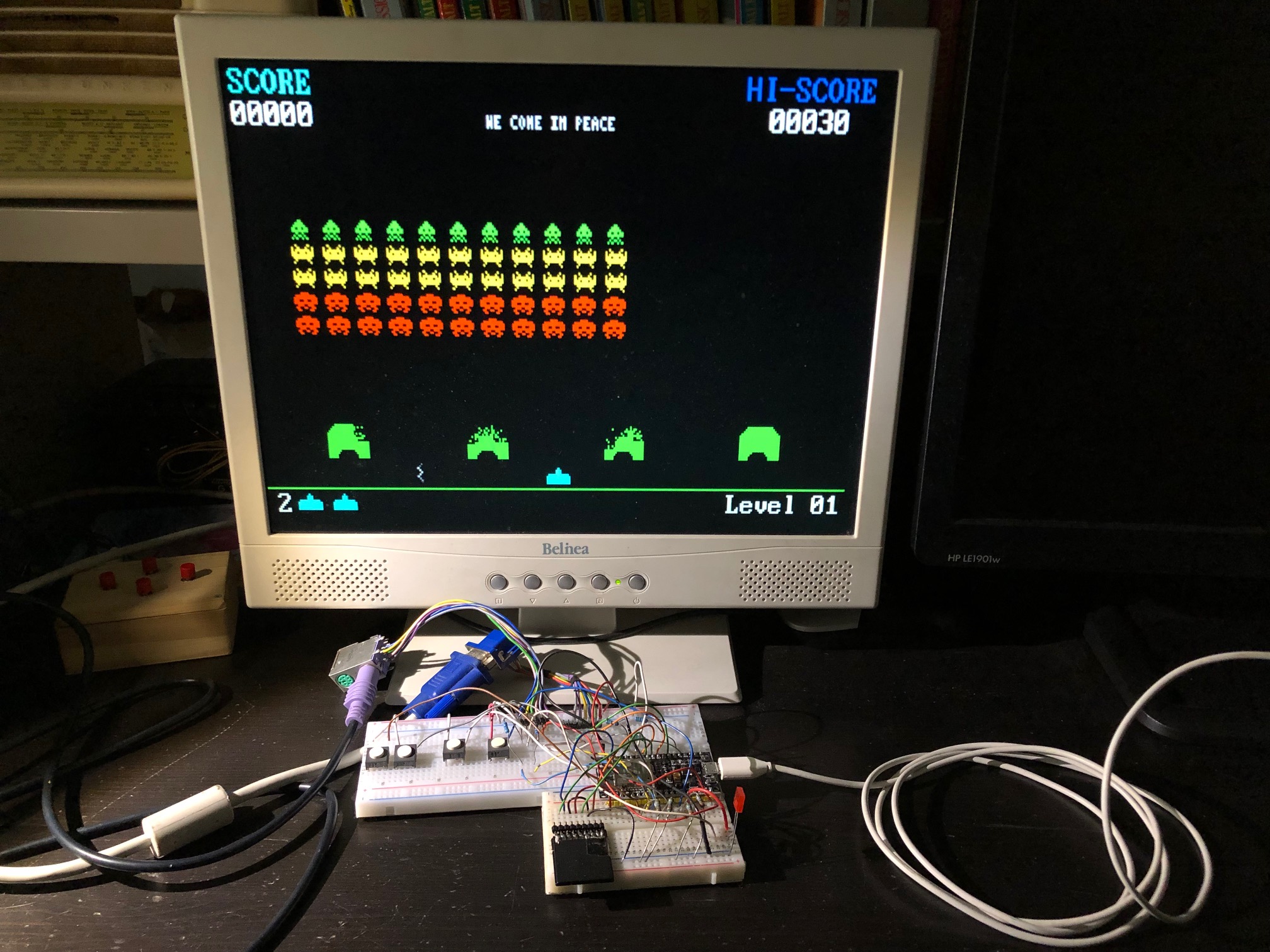
I wish to express my tanks to Fabrizio Di Vittorio for his awesome ESP32 VGA library. For more details, examples, and... Space Invaders, visit his site here.
many thanks also to the authors of Tiny Basic:
- Mike Field
- Scott Lawrence
- Brian O'Dell
Finally, if you like this project, please write a comment or share a picture of the device you build... and, over all, vote for it in the Arduino contest!