ESP32-Based Wireless Smartwatch | LiDAR Distance Sensor and WiFi Scanning | Gateway
by RoboticWorx in Circuits > Wearables
52524 Views, 451 Favorites, 0 Comments
ESP32-Based Wireless Smartwatch | LiDAR Distance Sensor and WiFi Scanning | Gateway

For the best quality read, check out this article on my homepage here. Also, don't forget to subscribe for free to support my work! :)
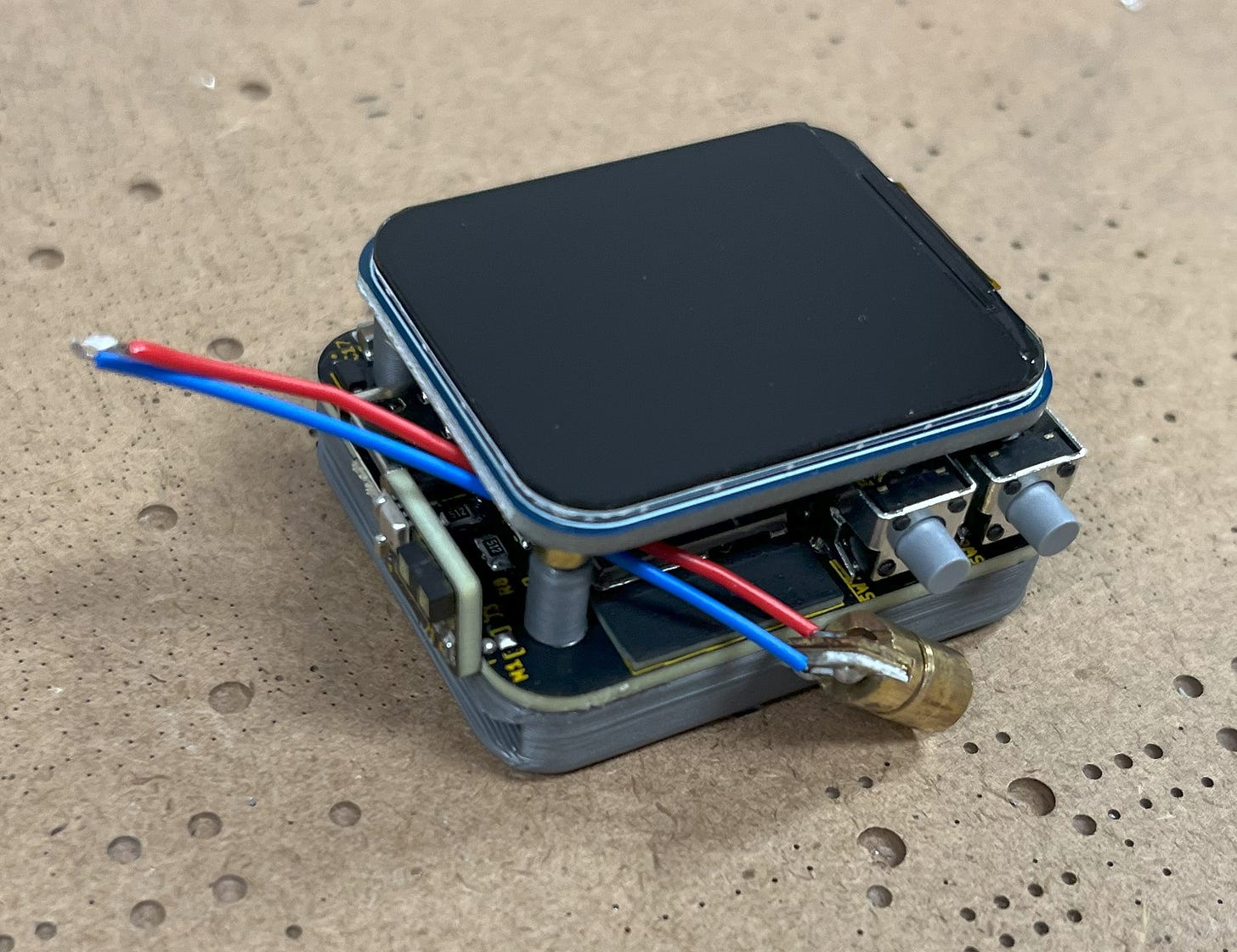
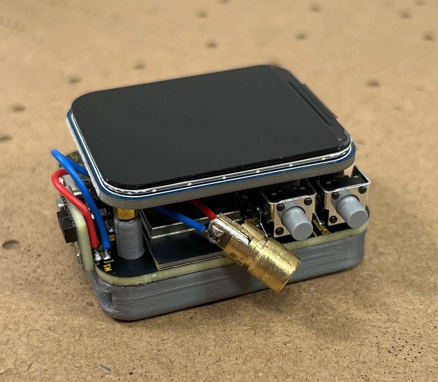
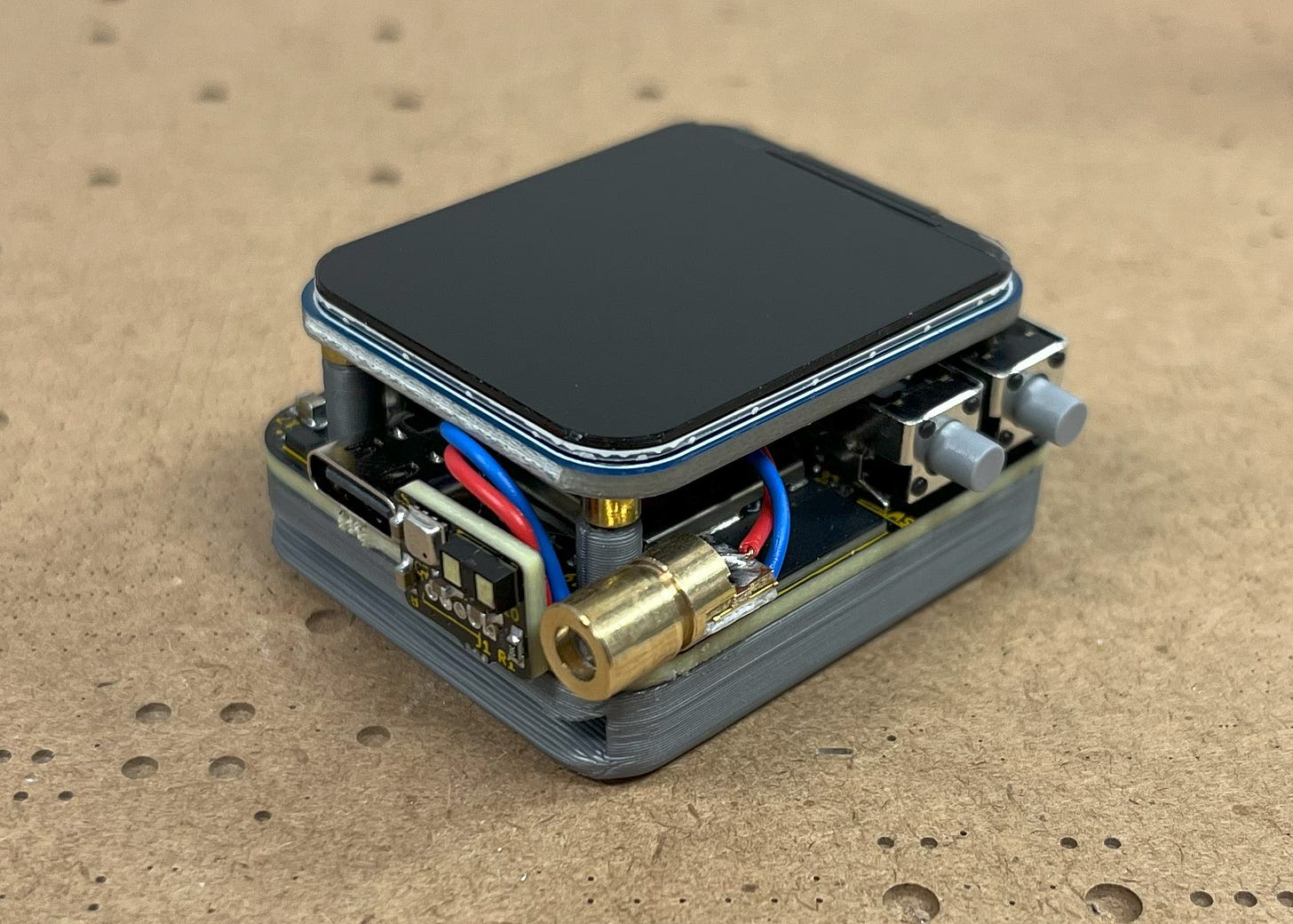
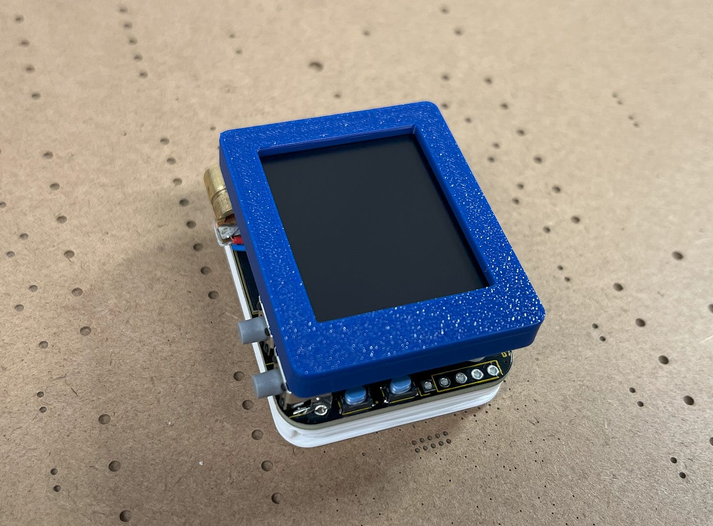
In this project, I will show you how to build an awesome ESP32-based smartwatch with numerous environmental sensors and a laser that you can use to control all of your other projects remotely.
A Quick Preview
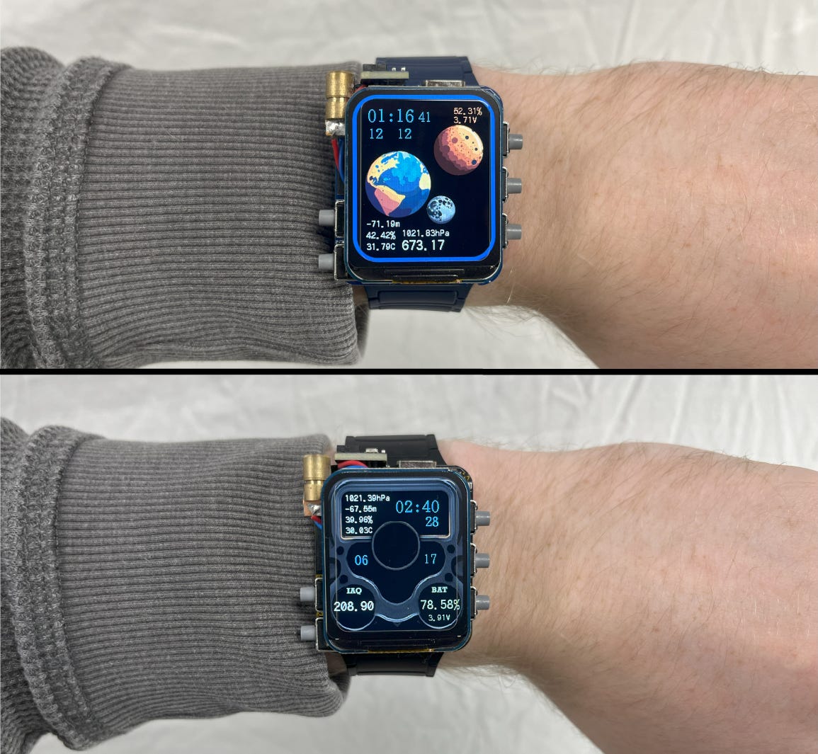
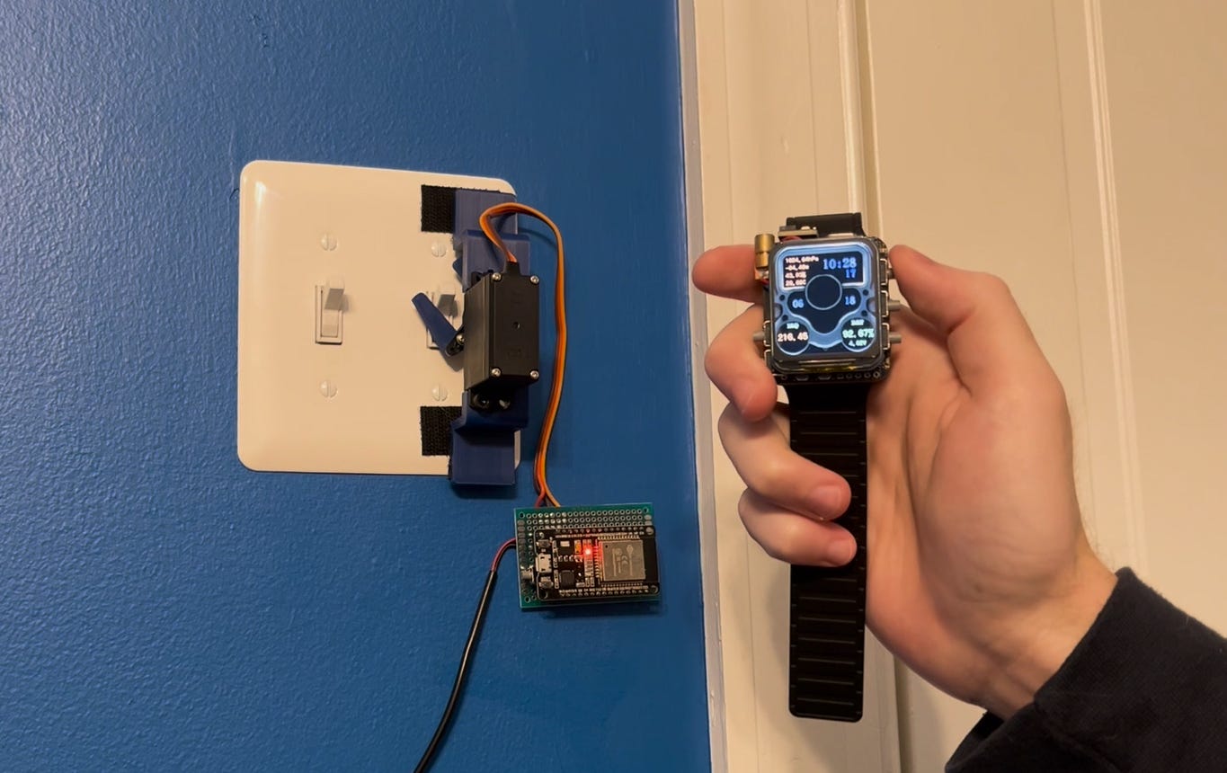
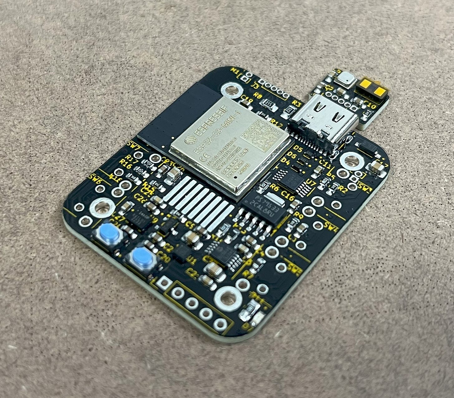
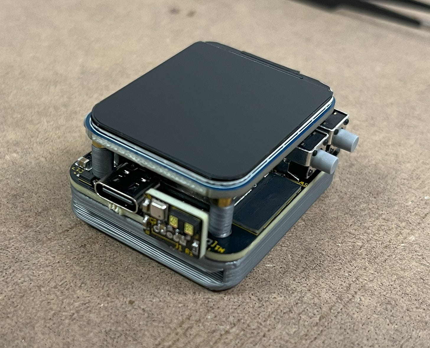
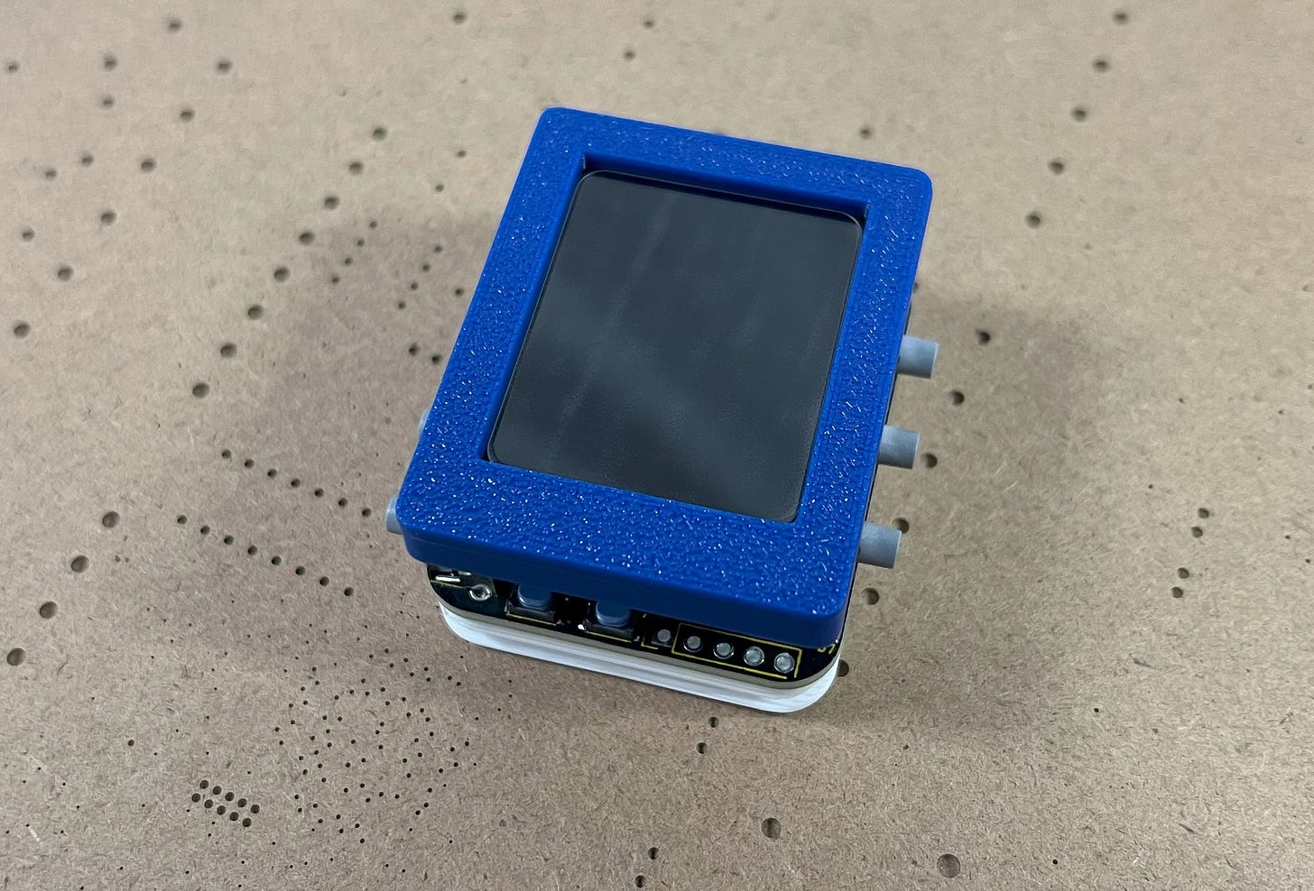
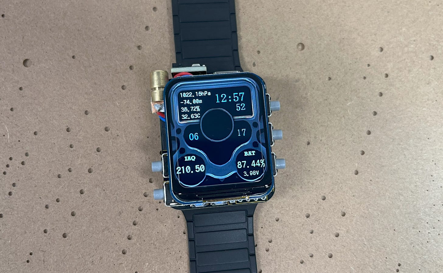
This is my “Gateway” smartwatch project! It acts as a compact wireless access key to control all your IoT devices from the comfort of your arm! It also features exchangeable MAC addresses, the ability to scan WiFi networks, has a built-in LiDAR for distance sensing, and provides you with real-time temperature, altitude, humidity, pressure, gas resistance, tilt, and acceleration.
Here’s a demo:
Continued..

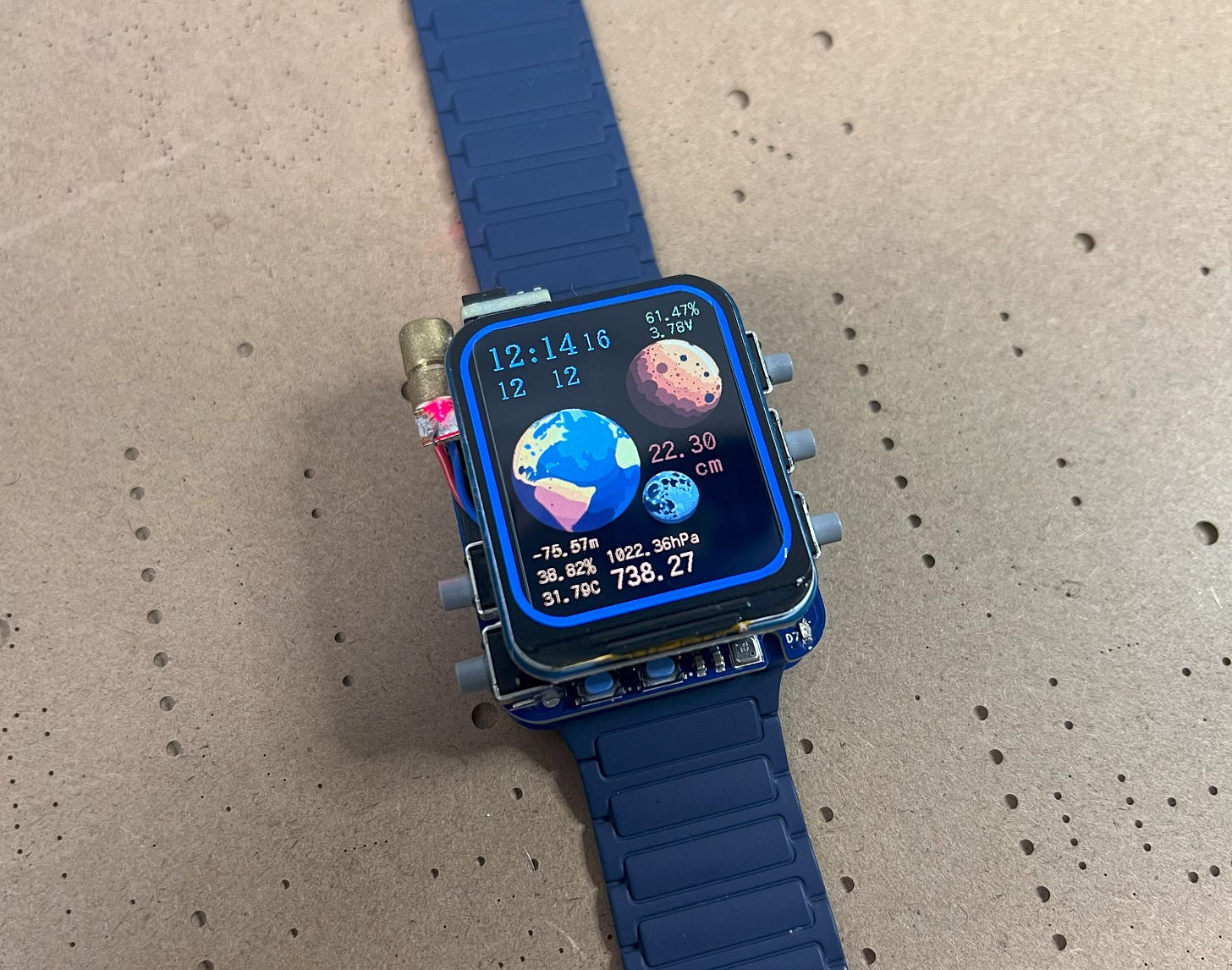
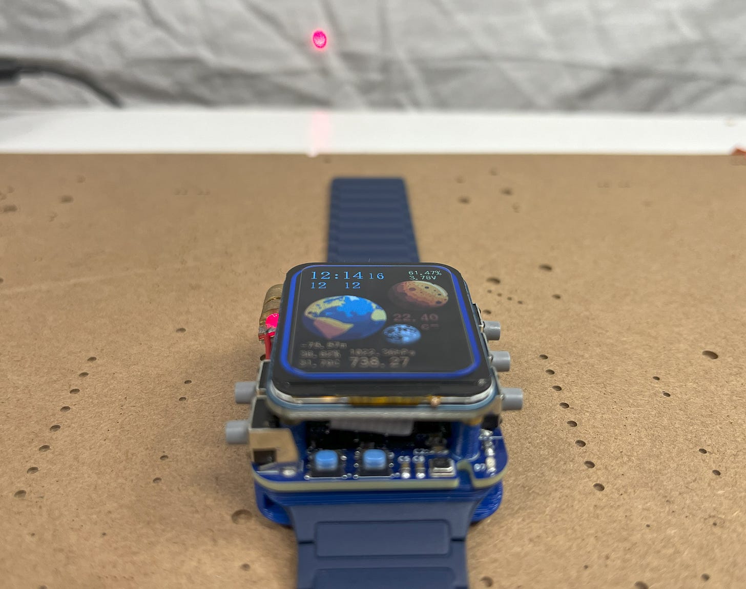
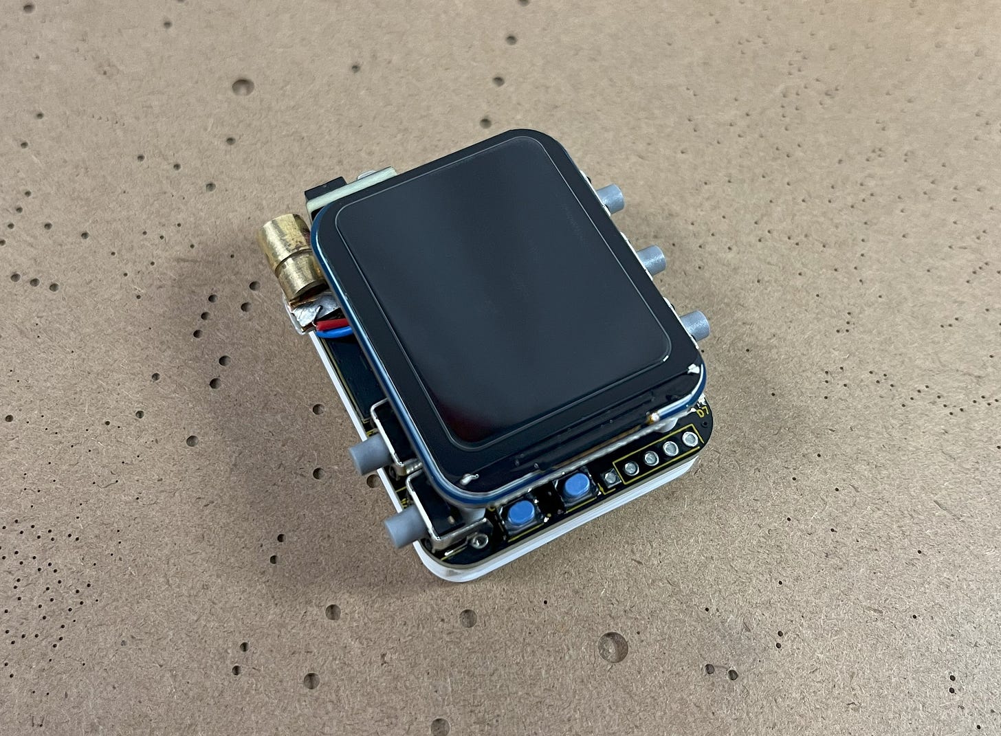
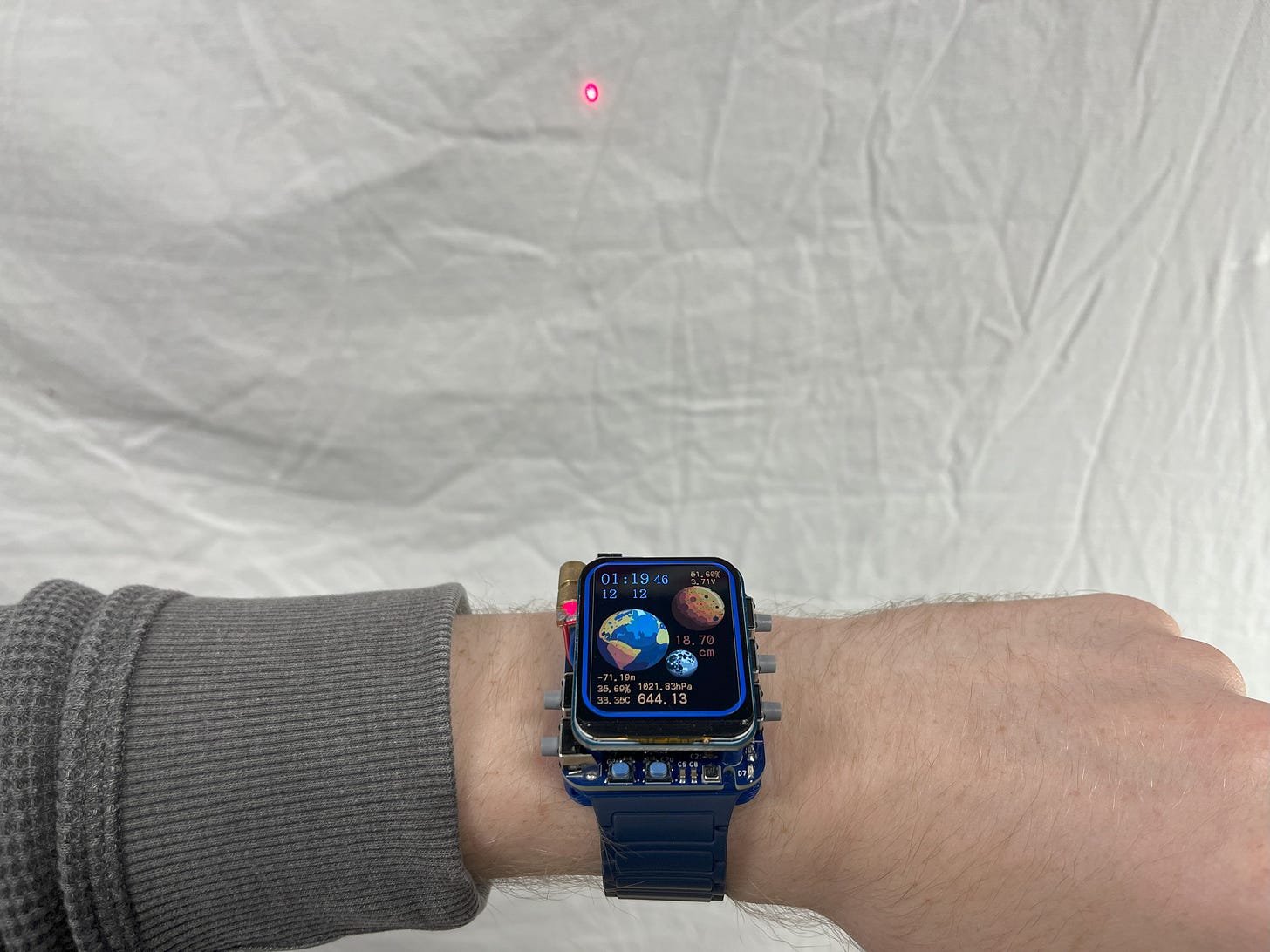
The LiDAR being used is a super neat VL53L1X ToF (time-of-flight) distance sensor from STMicroelectronics. It can measure any distance from 4cm to 4m with <±1% accuracy, perfect for taking measurements or if you’re just curious about how far you currently are from a wall. Since it uses a 940 nm laser (which is infrared and therefore invisible to the human eye), I also included a togglable bright red 650nm 5mW laser right next to it to assist with aiming or if you’re giving a presentation.
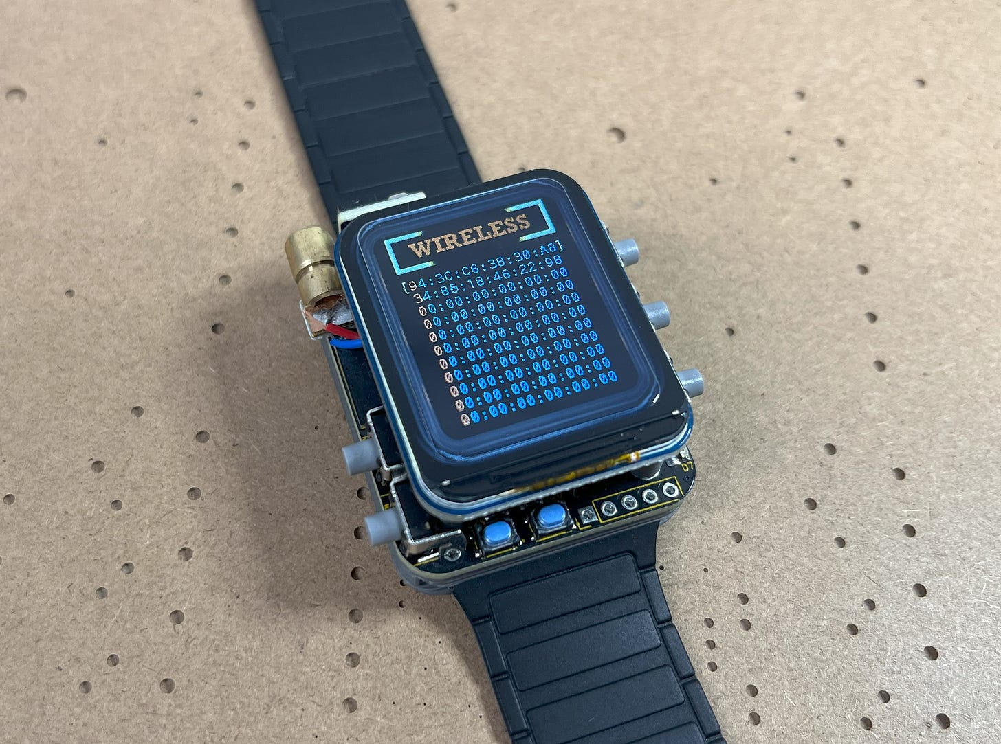
For the wireless portion, the watch utilizes ESP-NOW to quickly broadcast data with ultra-low power consumption. This wireless protocol was chosen over others because of its ability to bypass the traditional WiFi connection setup, which makes the action-reaction time between other devices nearly instantaneous.
*For most 32-bit MCUs.
Basically, you can think of ESP-NOW as just “throwing” data out there but only being readable to the receiving device’s MAC address. For higher security purposes (such as my door lock) the data can also be securely encrypted, making the watch the ultimate control device or “Gateway”.
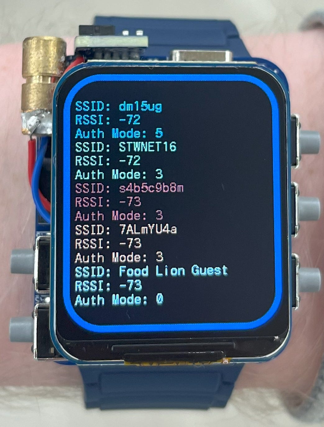
As seen in the video, the watch can also be used to scan WiFi networks and provide you with the network SSID, RSSI (signal strength), and Authentication Mode (how secure the network is 0-7). Here is the result of a quick scan I did at a local Food Lion grocery store:
Always interesting to see what strange networks have been lurking in the shadows!
Since broadcasting wireless data is pretty power-hungry, the watch is programmed to only activate WiFi momentarily to send/receive the data and then automatically disable itself afterward. It also has an automatic 1.5-second sleep mode timer and tilt-to-wake detection very similar to what you might experience on a standard Apple watch. Although, you can’t connect an Apple watch to a DIY door lock/light switcher. ;)
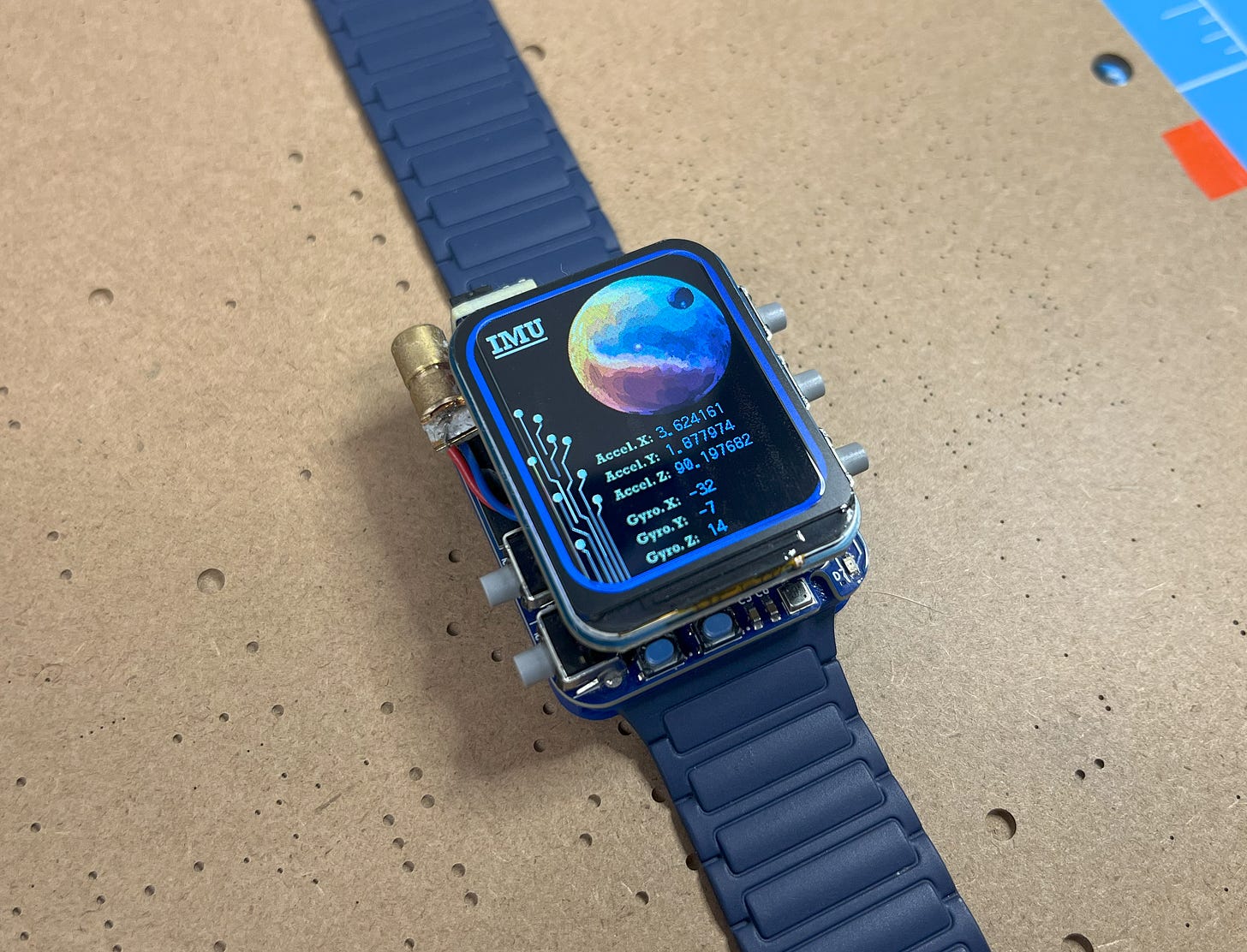
If all this isn’t enough, you can also use the watch as a digital level/slope detector. Just place the watch on the surface in question and click the IMU mode button to get access to real-time tilt and acceleration data.
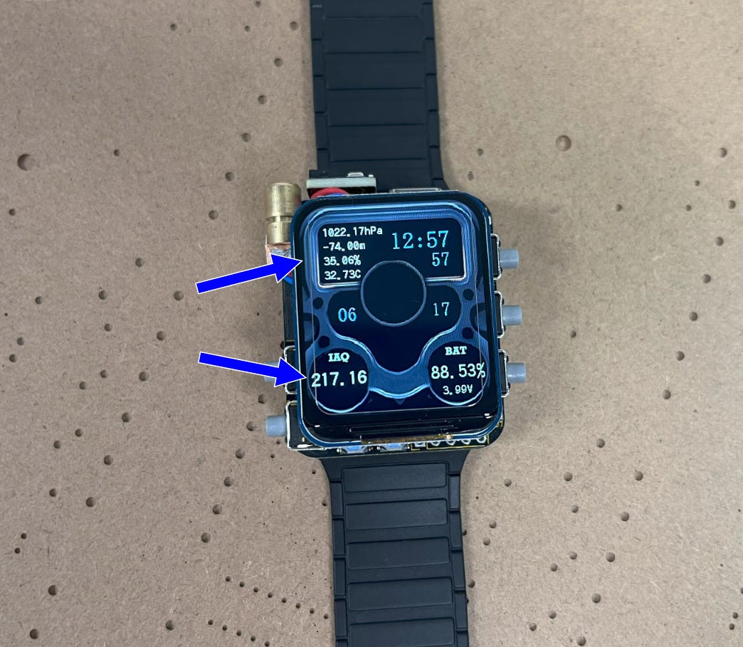
Have a questionable roommate? You can find out what he’s been up to using the watch’s built-in Volatile Organic Compound (VOC) sensor. Simply turn the watch on and watch the IAQ reading change from the result of target gases coming into contact with the heated metal oxide layer of the BME680. Being that this sensor also monitors humidity and pressure, it can grant helpful readings of the current altitude in addition to atmospheric changes. For example, I can usually predict a storm whenever the relative pressure reading drops ~10hPa below the usual level in the area where I live.
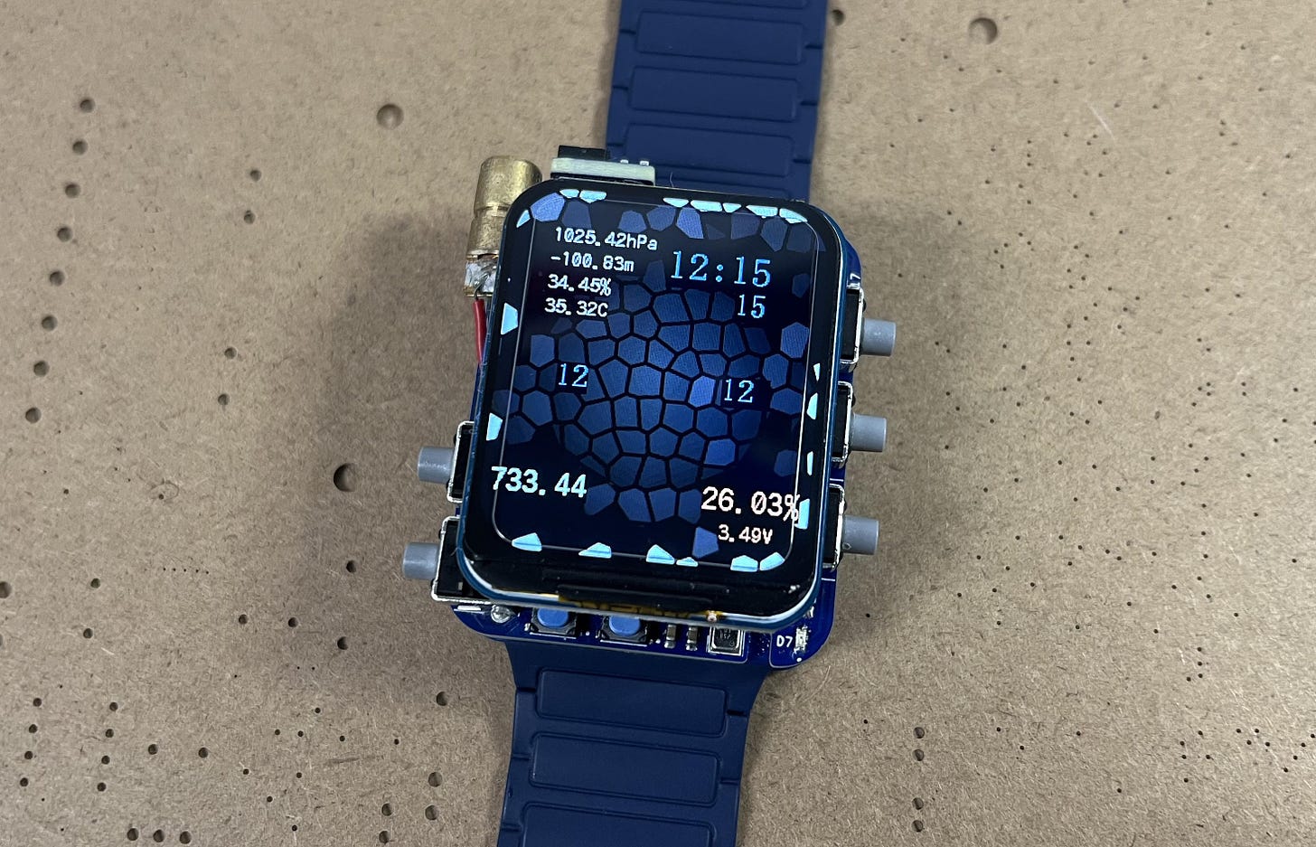
As you probably realized, the watch also comes with multiple themes so you can select the colors you like most. If you don’t like any of them, you can also easily create your own! But more on that later.
*Custom watch face.
This may be one of my coolest projects so far, which is why I’m so excited to share it with you completely open source! Let’s dive into how everything works in a bit more detail.
Working Concept
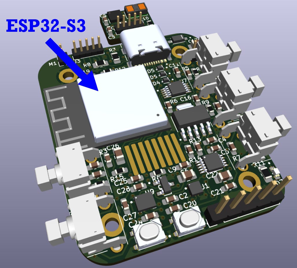
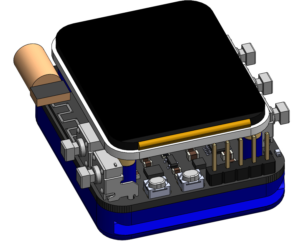
At the core of all these awesome functions is an ESP32-S3-MINI microcontroller or MCU. This handles all the communication between the display, various sensors, and other wireless devices. If you want to learn more, I wrote an entire article about building ESP32 MCUs and how they work here.
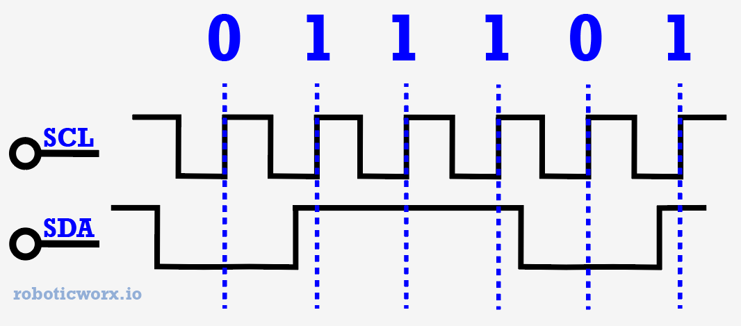
To communicate with these sensors, the MCU utilizes I2C (inter-integrated circuit), which is a popular two-wire communication protocol that uses a clock and data signal to read and write data to different addressed sensors.
From there, there are five general-purpose buttons to take user input and react accordingly. I have a section detailing the different functions and combinations further down in the article.
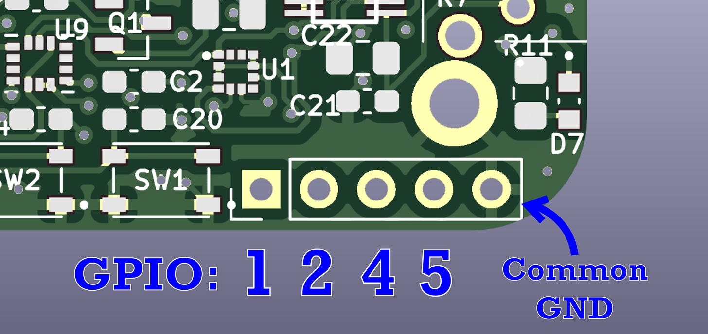
You may have also noticed from the image above that I broke out a few GPIOs on the bottom right. These don’t currently do anything, but I thought they’d be cool to add in case you want to edit any of the code to use them for miscellaneous tasks or as a digital password.
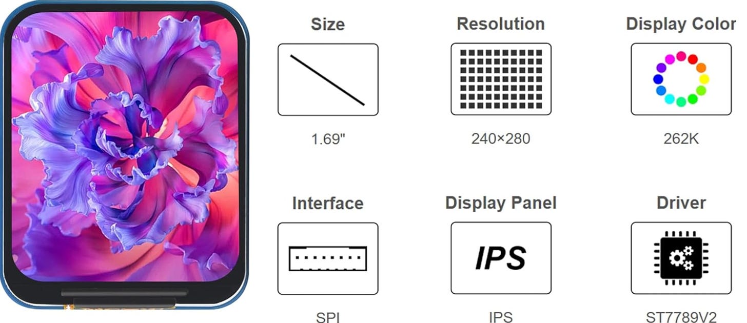
The display being used for this project is a 280x240 resolution 1.69” 262K RGB LCD driven by an ST7789 via Serial Peripheral Interface or SPI. Perfect for illuminating high-resolution images.
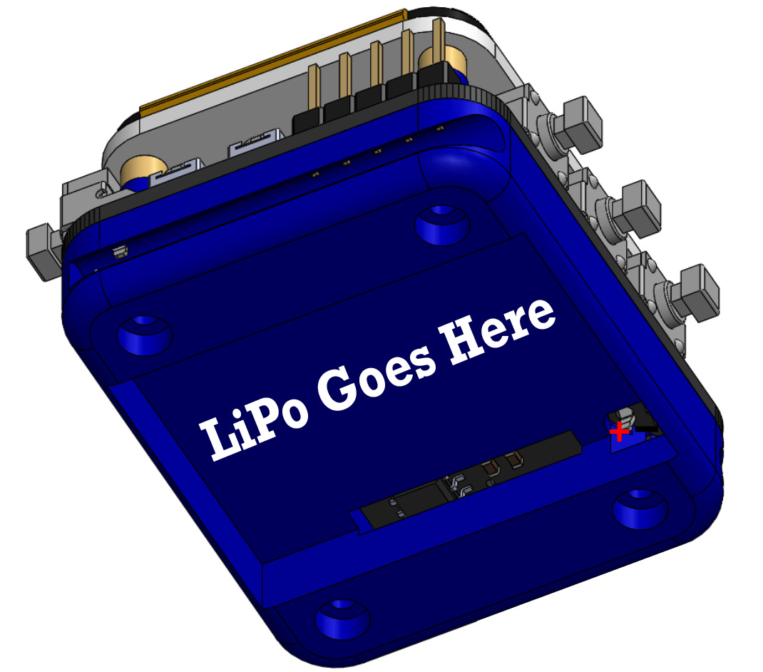
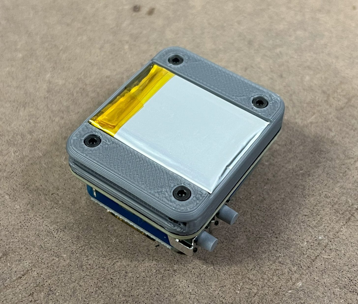
To power it all, I’m using a rechargeable 400mAh Lithium-ion Polymer (LiPo) battery which I’ve slid under the watch band casing.
Harnessing its power, the watch can last 14 hours (standard use) with a full charge time of <43 minutes. Not too shabby for a DIY watch!
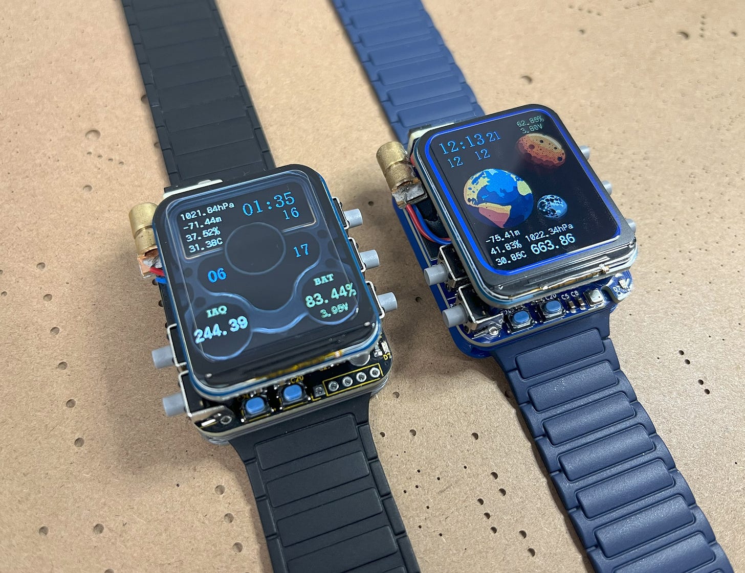
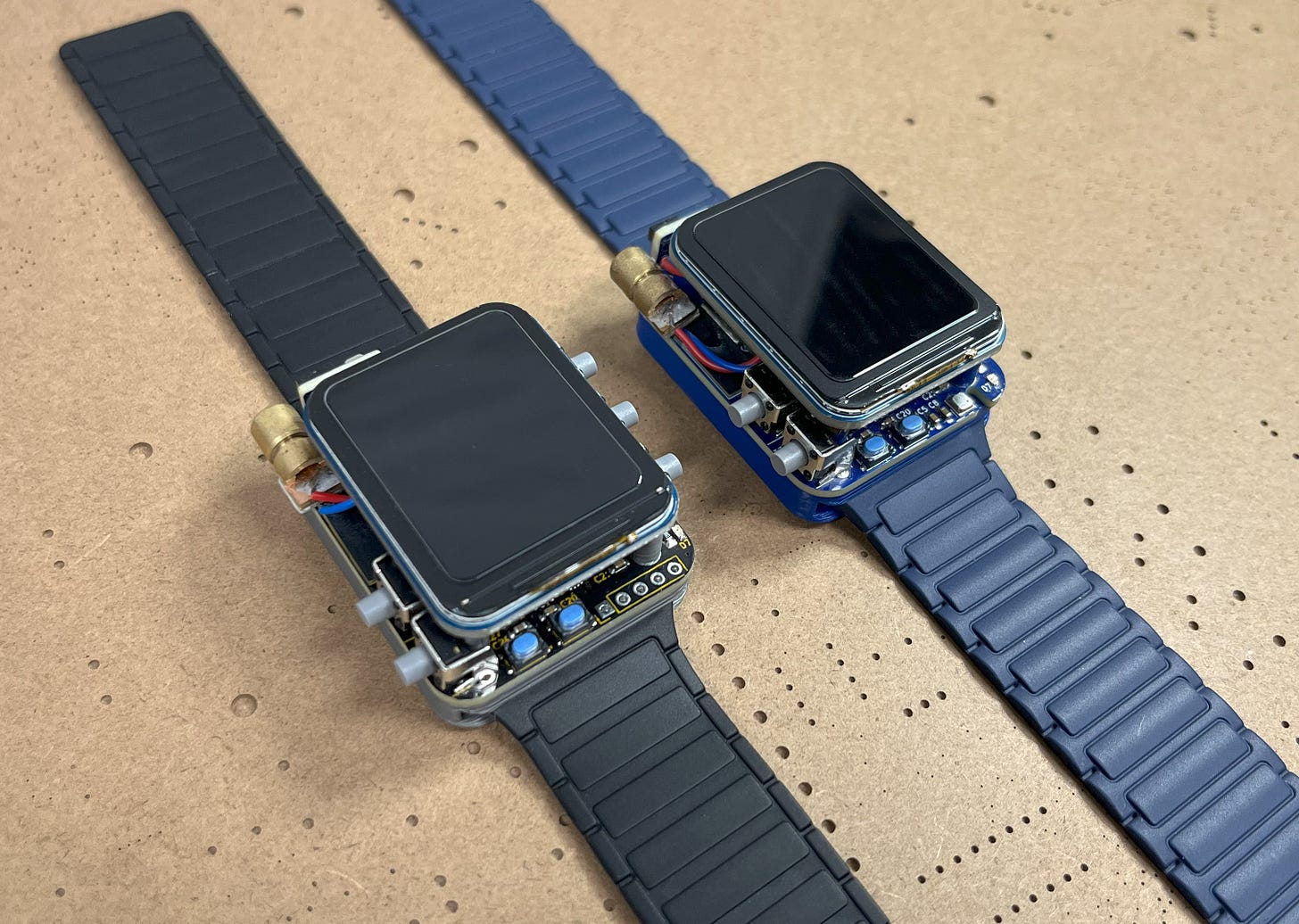
If you’re wondering why the blue version of the watch looks slightly different from the black one, it’s because the blue PCB had a few errors which were fixed with the black one. They both work, but the newer (black) one works better. Don’t worry though, all the files posted to build this project (regardless of the color you choose to build it in) have been updated to the newest version.
Understanding the Hardware
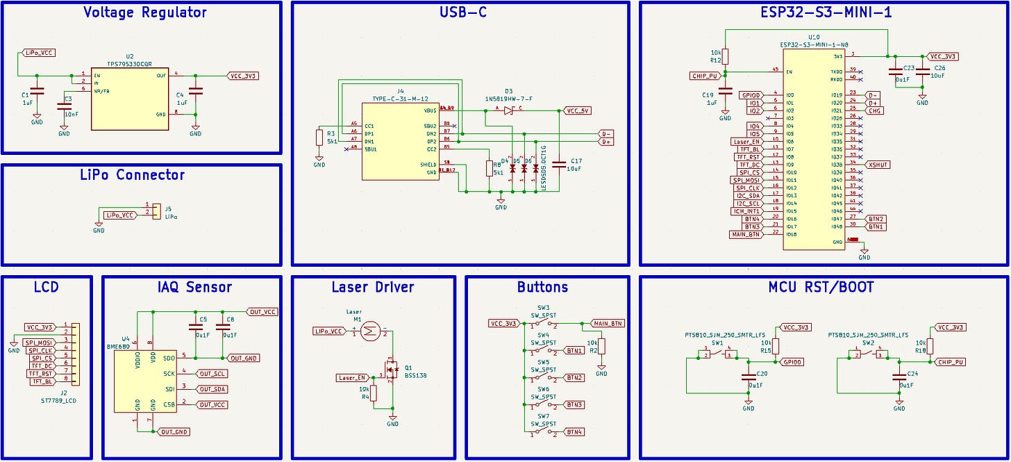
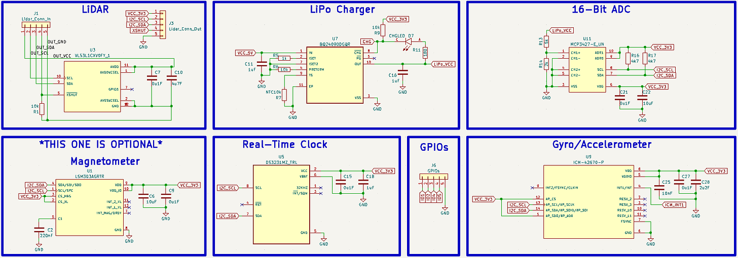
Our main circuit here consists of five sensors (with an optional sixth), a LiPo battery charger, a laser module driver, and the typical circuit for powering, communicating with, and setting up the ESP32-S3 microcontroller. Along with some buttons and connectors of course. Here is the full schematic:
Let’s break it down.
It should be noted that I won’t explain the microcontroller schematic in this article since I covered it in detail here.
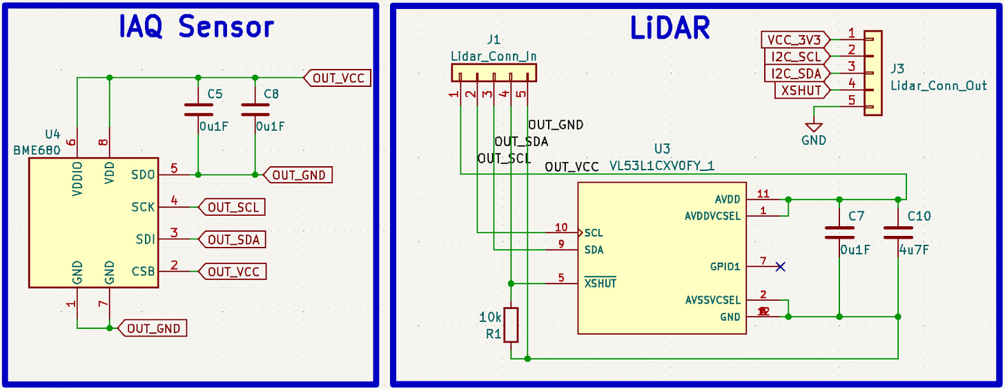
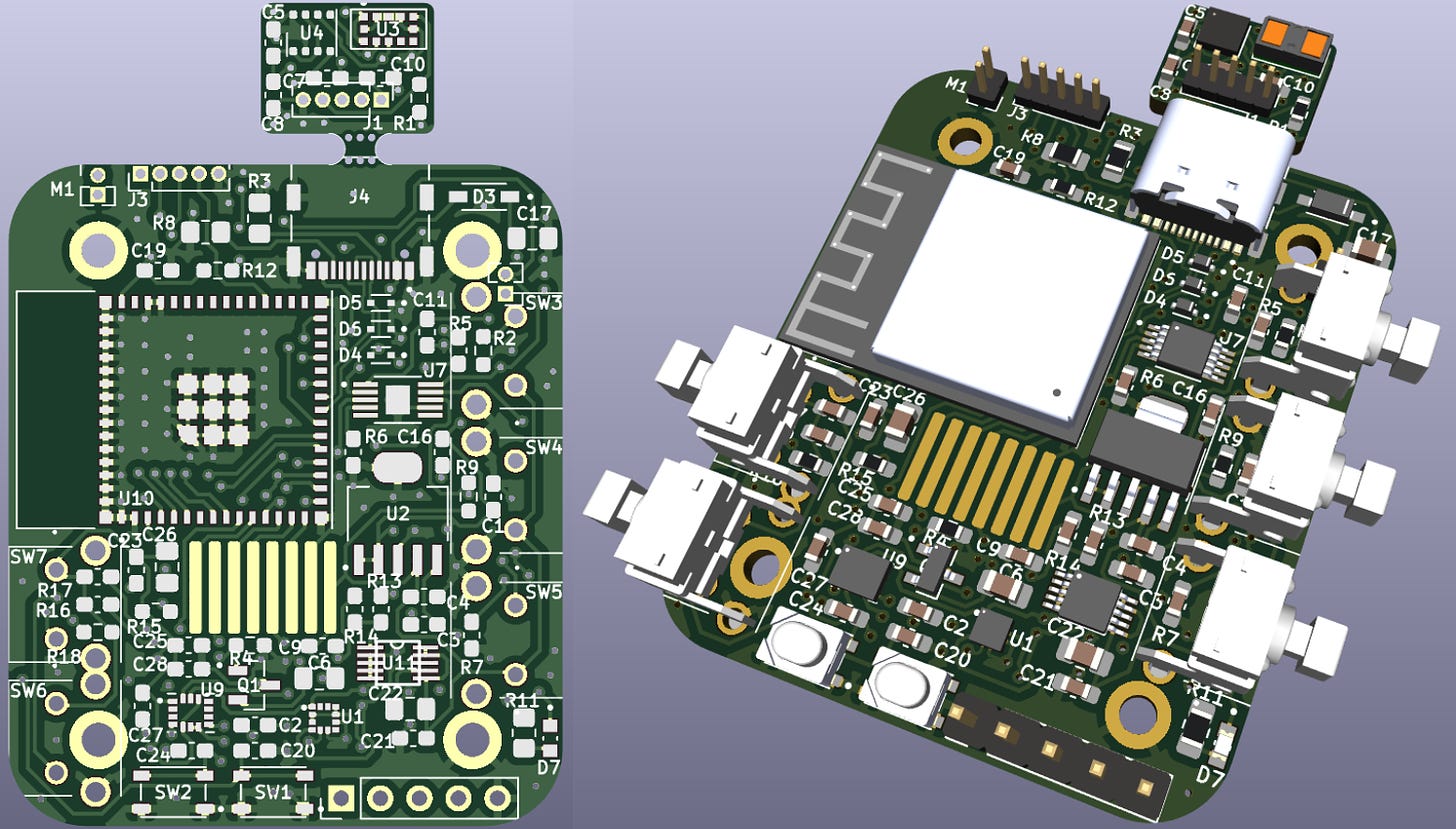
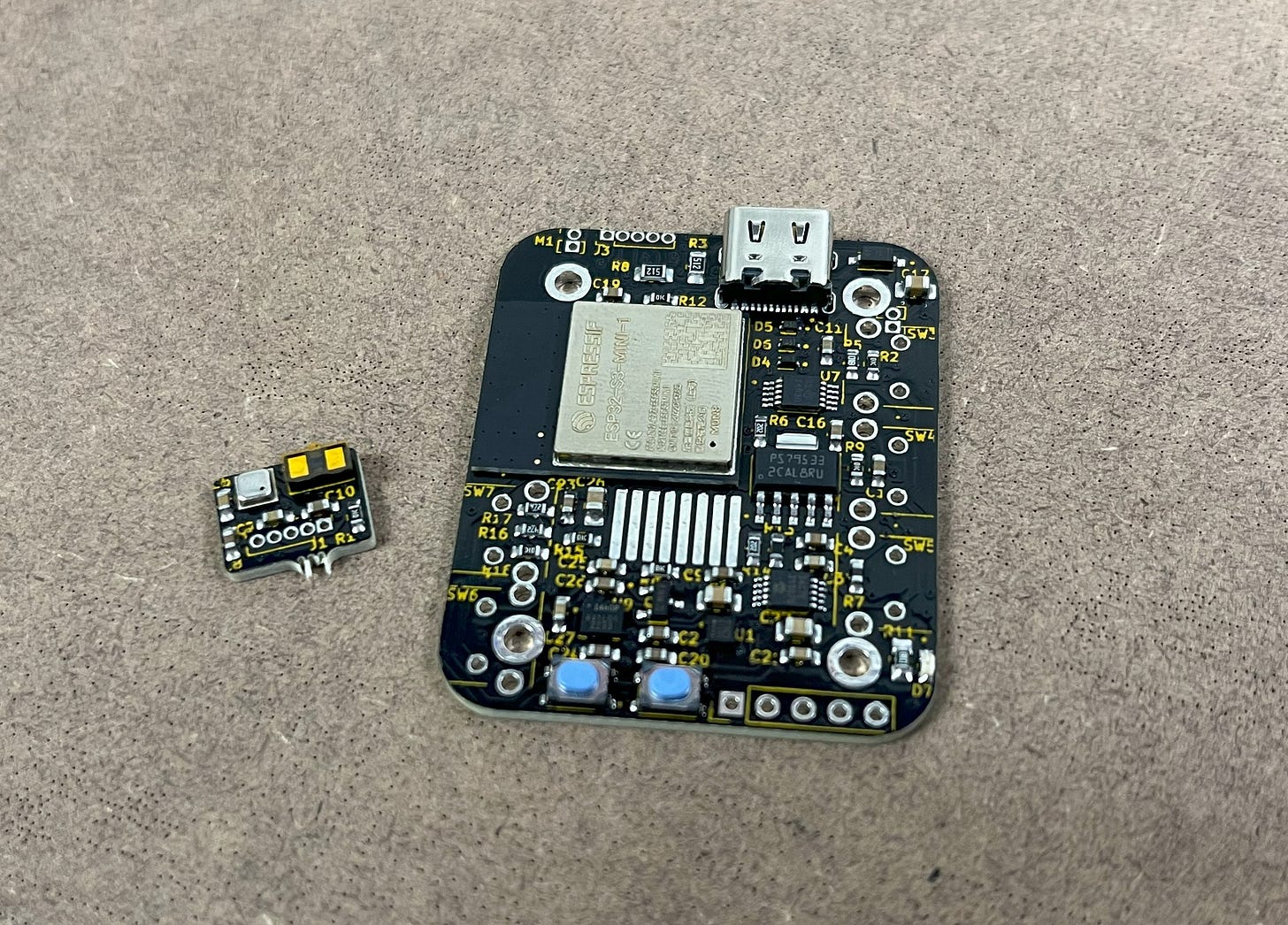
We can start with the IAQ sensor and LiDAR. These two sensors have different global labels than the rest because they are mounted on the vertical portion of the PCB (not part of the main circuit board). This is because:
- The LiDAR needs to be perpendicular to the watch to point at things.
- Environmental readings from the BME680 will be more accurate the further it is from other heat-generating components.
It should also be noted that the VL53L1X LiDAR works best in low ambient light environments. I’ve had no issues when using it indoors, being even better when the lights are off. But, when using it on a sunny day, the ambient light from the sun can introduce noise into the sensor's measurements which reduces the accuracy and reliability of the distance readings. In addition, while the laser pointer is being used to help aim the LiDAR, it is not always a direct indicator of the measuring location. The VL53L1X distance measuring algorithm basically works by taking an area around the center location (about 9.8 degrees in all directions from where you point it) to get a bigger sample of incoming light. It then uses this combined reading to calculate the distance. This said, if you’re trying to measure an environment with lots of stuff close to the laser dot, the measured distance will be a combined reading of what the dot hits + the stuff nearby (within 9.8 degrees).
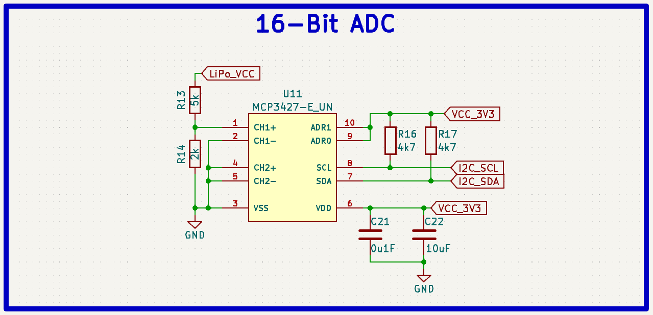
The capacitors C5, C8, C7, and C10 are all used for decoupling to smoothen out the power supply input to the chip. The values were determined by the LiDAR and BME680 datasheets. R1 is being used as an extra pull-down resistor to ensure the LiDAR is disabled when not in use. There are no pull-up resistors for the I2C communication on these since the line is already being pulled up in the MCP3427 ADC circuit (used for battery monitoring) which we can look at next.
Note: The temperature readings from the BME680 may be a bit high due to escaping body heat. I have found that this value -5C is normally the correct temperature.
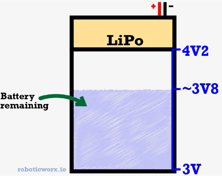
This MCP3427 Analog-to-Digital Converter (or ADC) is pretty similar to the last in terms of the decoupling capacitor values being determined from the part datasheet. However, in this case, the I2C lines are getting pulled up and there is a voltage divider on the left side (R13 and R14). This voltage divider is important because we want to proportionally decrease the input voltage from the LiPo battery to a voltage low enough to be read stably by the ADC. Since battery voltage decreases with charge, this read voltage will be a strong indication of how much battery is remaining in the watch.
If you’re wondering why I’m using a two-channel ADC even though I only need one, it’s because the MCP3427 has the cool ability to select up to eight different I2C addresses. There was a conflicting address problem with my usual ADC (the MCP3425), so I had to switch to the 3427 to resolve it. This is also what the ADR1 and ADR0 pins are for (address selection) if you were curious. Let’s move on to the timekeeper chip.
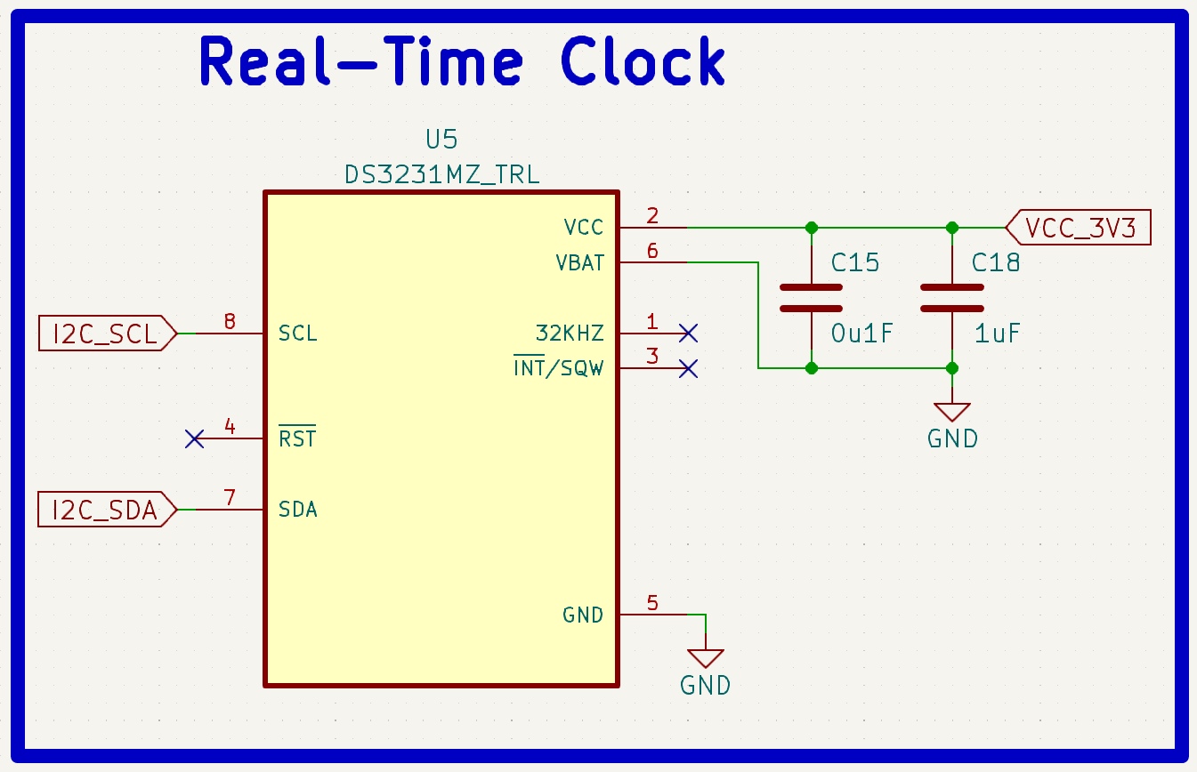
Basically, this chip’s sole purpose is to count. It’s a low-power, high-accuracy Real-Time Clock (or RTC) that has a built-in calendar up to the year 2100. This is useful since it means it will be able to count for extra days and such depending on the month and year. There’s nothing too interesting about the schematic, just a few decoupling capacitors from the datasheet.
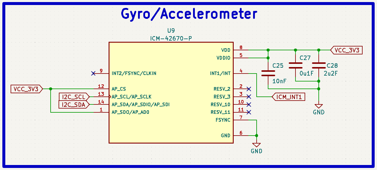
The main Inertial Measurement Unit (IMU) I chose for this project is the ICM42670 gyro/accelerometer. This is what gives you all of that awesome tilt data in addition to waking up the ESP32-S3. This IC is really important as a low-power solution because the “waking up” is handled completely by the ICM42670 independent of the main microcontroller. The ICM42670 monitors the accelerometer constantly and then writes the INT1 pin high when the preprogrammed threshold is hit. This means all the microcontroller has to do is monitor the INT1 pin which saves a lot of power. As far as the decoupling capacitors go, it’s the same deal as before with the AP_CS and AP_SDO pins high to tell the chip that we want to communicate via I2C rather than SPI.
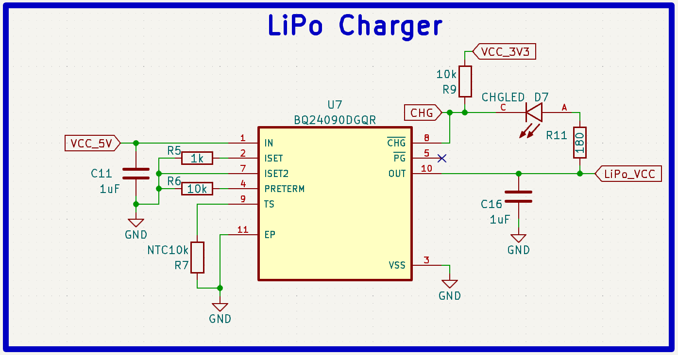
To handle charging the LiPo battery, I’m using the same BQ24090DGQR that I’ve used in all my other projects but with an added 10k thermistor (R7) to ensure automatic shutdown if the battery ever gets too hot. This schematic uses the same standard decoupling caps C11 and C16 but with some extra resistors R5 and R6 to set charge termination and speed. All R11 does is protect the charging LED so it can be increased if you’d prefer the LED to be dimmer. R9 is used to pull up the opposing side to ensure the charging LED only turns on when the CHG pin is pulled low. I also connected this pin to the microcontroller so that I could do a cool color change on the screen when the USB-C is plugged in.
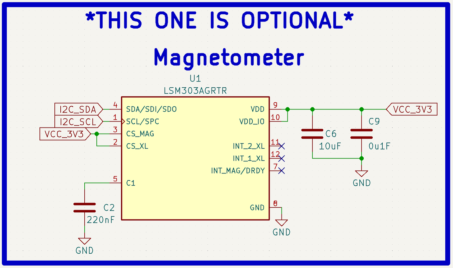
As far as the magnetometer goes, I left space to implement it on the schematic and PCB but it’s not supported in the programming. I wasn’t able to get it working with the code on time but figured I would leave it in anyways in case someone else wants to mess with it. It does no harm! If you’re able to get it working, let me know and I’ll update it.
Now let’s check out the laser driver!
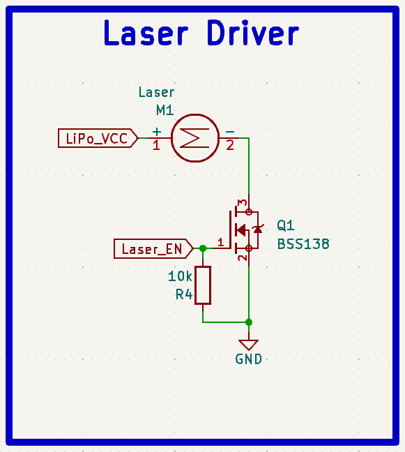
What this circuit does is take a low current input from the microcontroller to activate a small MOSFET, which when on, allows a higher current to flow through the laser diode to the ground. I also connected a pull-down resistor to the MOSFET input to ensure that the digital switch only turns on when the microcontroller sends a high signal. That’s it!
Will There Be a Version 2?
Definitely! This has been a super practical project (and personal favorite), and I’ve already had lots of ideas that I want to implement on a v2. This will hopefully include:
- Further RFID capabilities that are similar to what the Flipper Zero can do (might be saved for v3 depending on how challenging it is to implement).
- An infrared camera (for thermal imaging) that’s built into the watch for temperature sensing at 32x24 resolution (confirmed).
- Touch screen!
- Long-range radio communication for sending commands via a LoRa module.
- 5GHz wireless capabilities (hopefully the ESP32-C5 will be out for this).
- GPS live-coordinate capabilities.
- Finishing the implementation of a magnetometer.
- Live camera monitoring (external cameras feed onto the watch display).
- Improved battery life.
No doubt these will be pretty hard to implement considering that the PCB I designed for the watch is already crammed full of components. If you’d like to see how I attempt it, be sure to subscribe or even consider becoming a paid subscriber since I’m sure it’ll be pretty expensive to prototype. I could really use the help!
Is there something else you want to see on version 2? Let me know your thoughts and feedback in the comments!
Building the Board
Now let’s explore how the actual PCB (Printed Circuit Board) was designed and the board assembly.
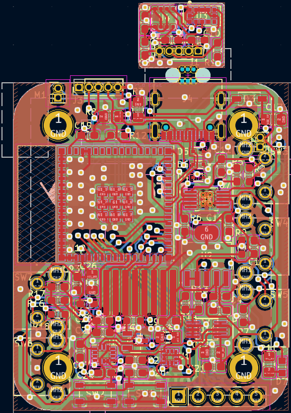
Being even more compact than my Solder Sustainer v2 PCB, this was no easy task. There were so many connections needed in such a small space (43x36mm) that I had to build it as a four-layer board instead of my usual two-layer. This way, I could put extra connections on the back and still get good isolation thanks to the two ground layers in between.
- The Gerber/fabrication file for the board can be found here.
- Editable KiCad PCB files are available here to paid subscribers. Want to become a paid subscriber? It’s only $5 and I would really appreciate your support!
- The part list for the PCB can be found here with the placement sheet available here.
- As always, I know that it can seem like a pain to have to order parts but it’s really not so bad as almost all the parts you order from one project get reused. Think about how much you’ll learn with some hands-on experience!
If you’re interested in learning more about PCB layouts and routing, check out Robert Feranec and Phil’s Lab on YouTube. They’re great designers and I’ve learned a lot from them. I also explained a lot about how I route my PCBs in my MCU article.
Now all we need to do is get the board made. A perfect job for my go-to PCB manufacturer, PCBWay!
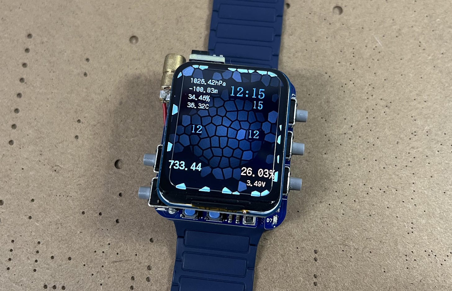
Their PCB quality is always incredible, and they even have other services available such as 3D printing and CNC machining. PCBWay also features nine different solder mask colors to choose from and three different silkscreens which is pretty awesome. I chose mine to be black and yellow to try and go for a steampunk-ish theme but that’s just me.
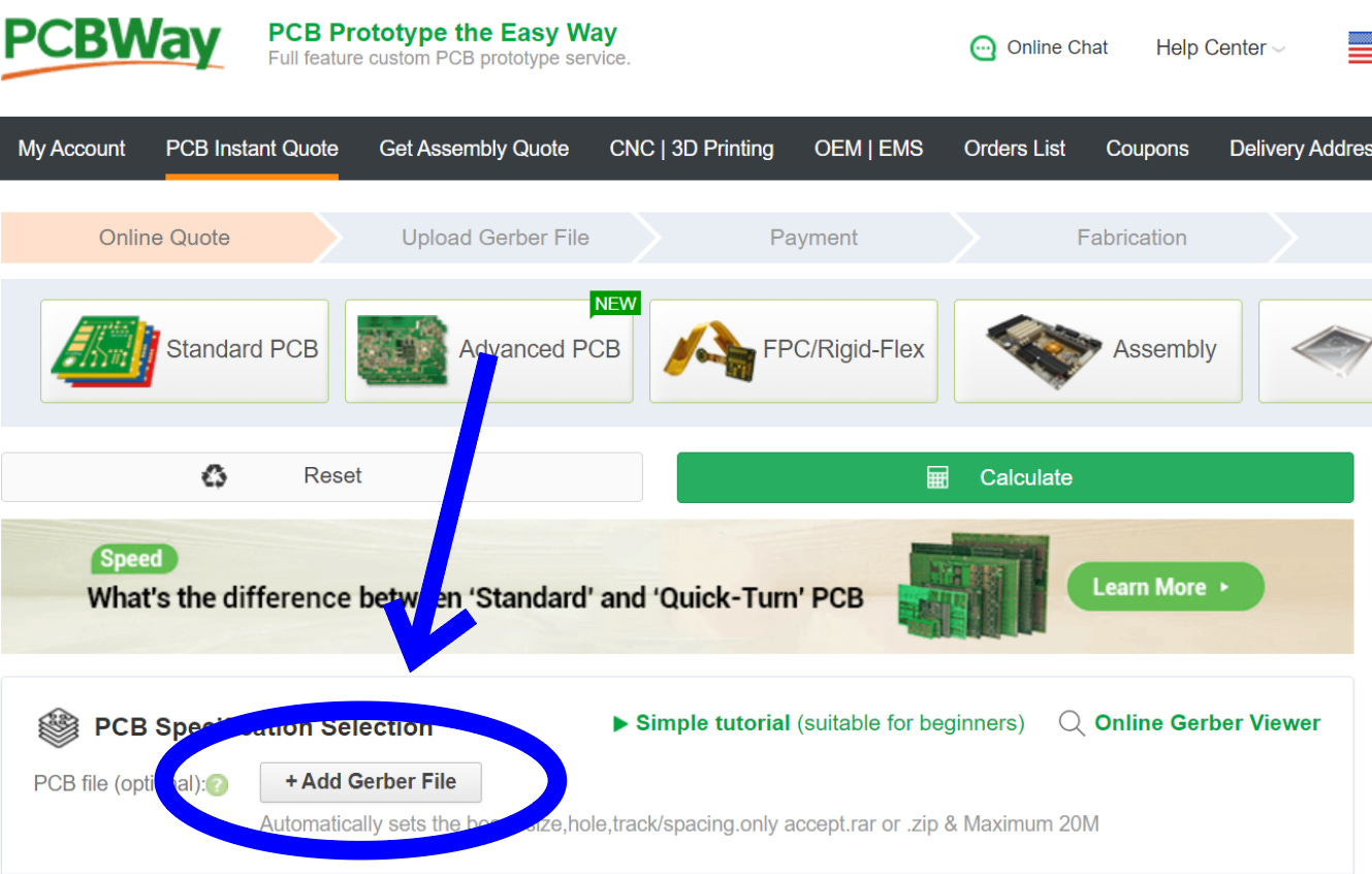
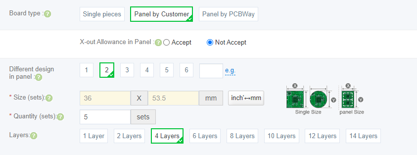
Since I designed with KiCad, I didn't even have to leave my design software to check out thanks to their convenient plug-in! If not though, you can always just go to PCBWay.com, click on quick-order PCB, and upload the Gerber file for the board. Or alternatively, just go here which I have saved in my favorites bar. I recommend clicking the stencil option at checkout to save some headaches!
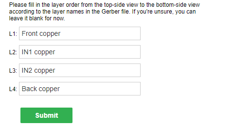
If you’re asked about the stack-up, you can just fill it out like so:
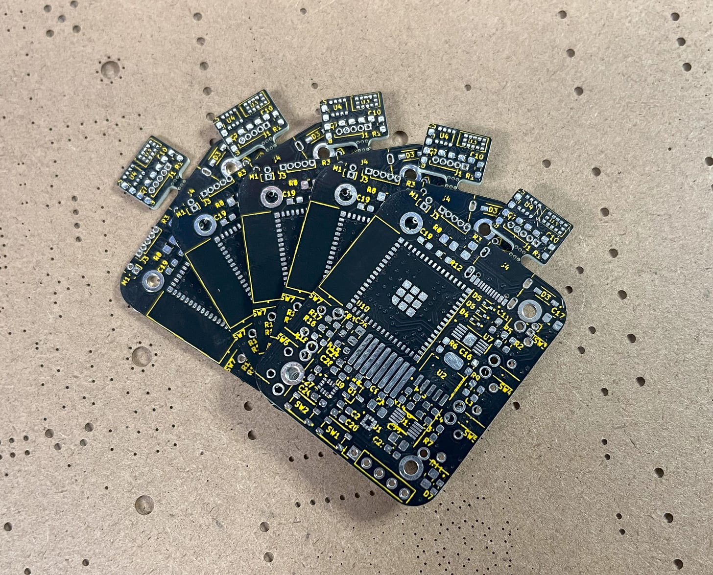
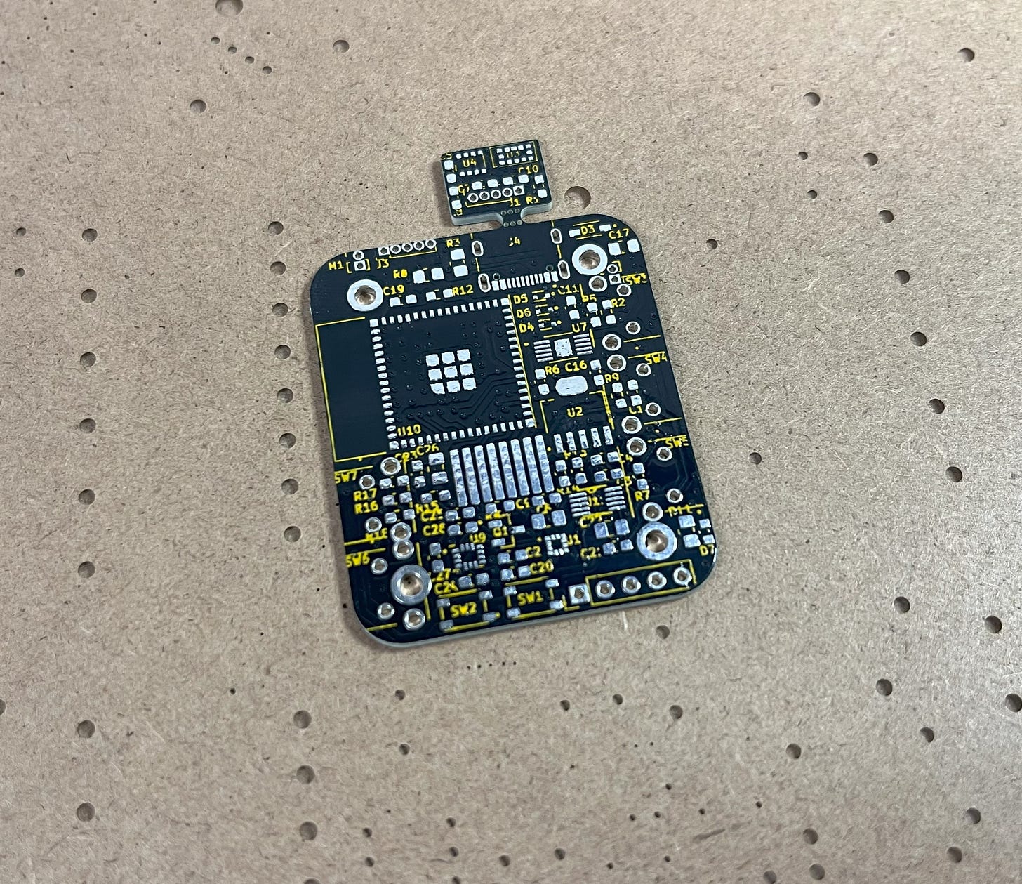
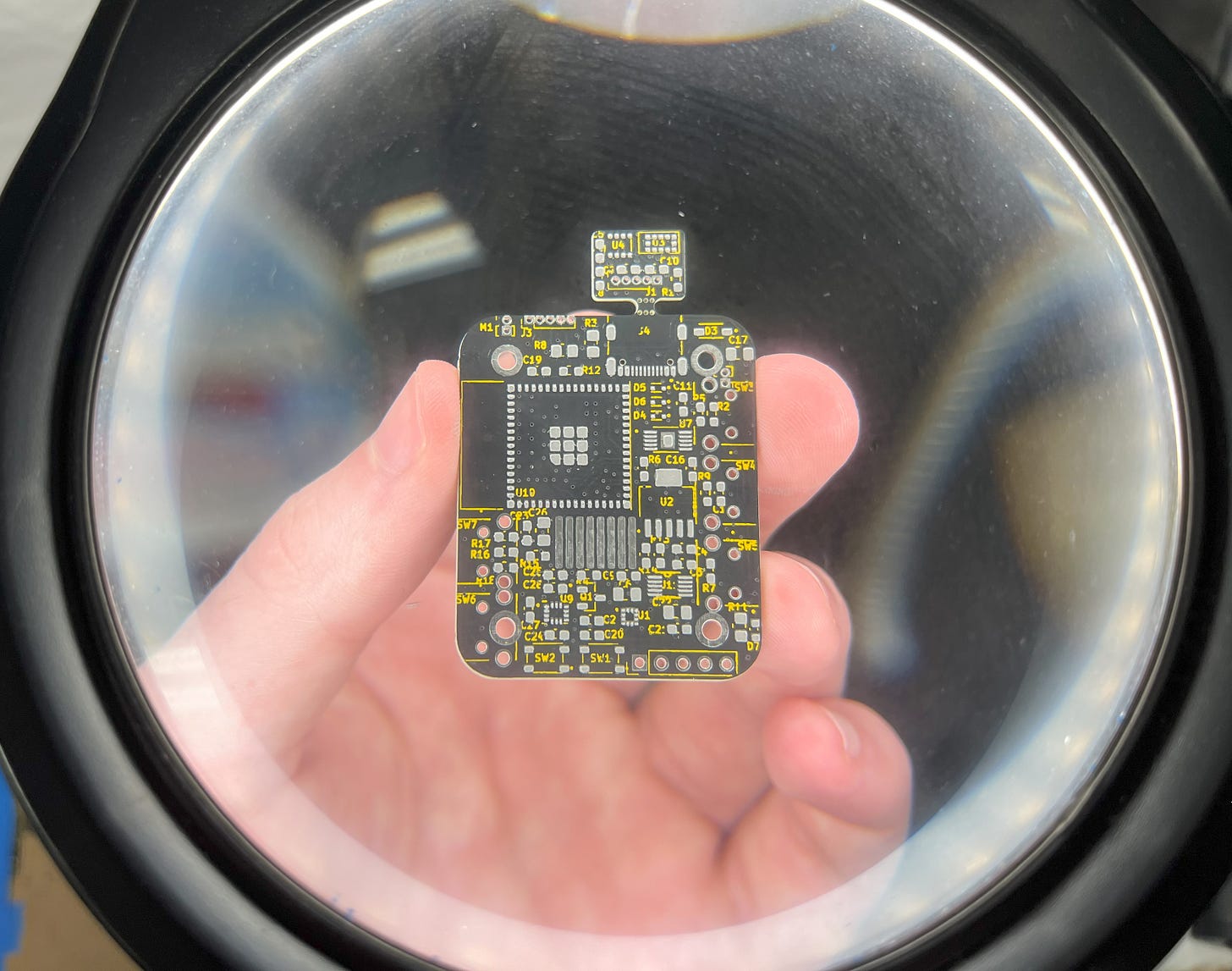
As usual, the PCBs looked fantastic when they arrived a few days later!
Now it’s time to get assembling! The reference/placement sheet for the PCB can be found here. Due to the compactness of the board, it may be hard to read the component number on the silkscreen in some places. To fix this, I found it easiest to just upload the Gerber file to this online Gerber viewer (courtesy of PCBWay) and then place the components relative to there since it’s much more legible.
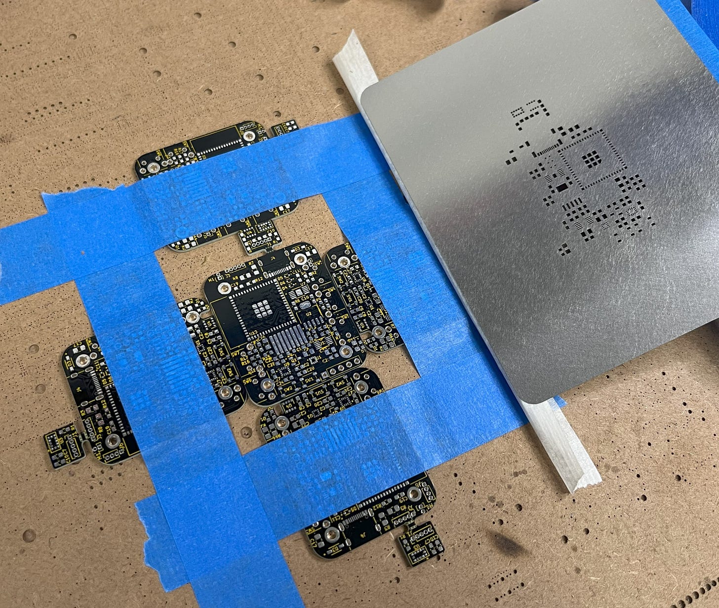
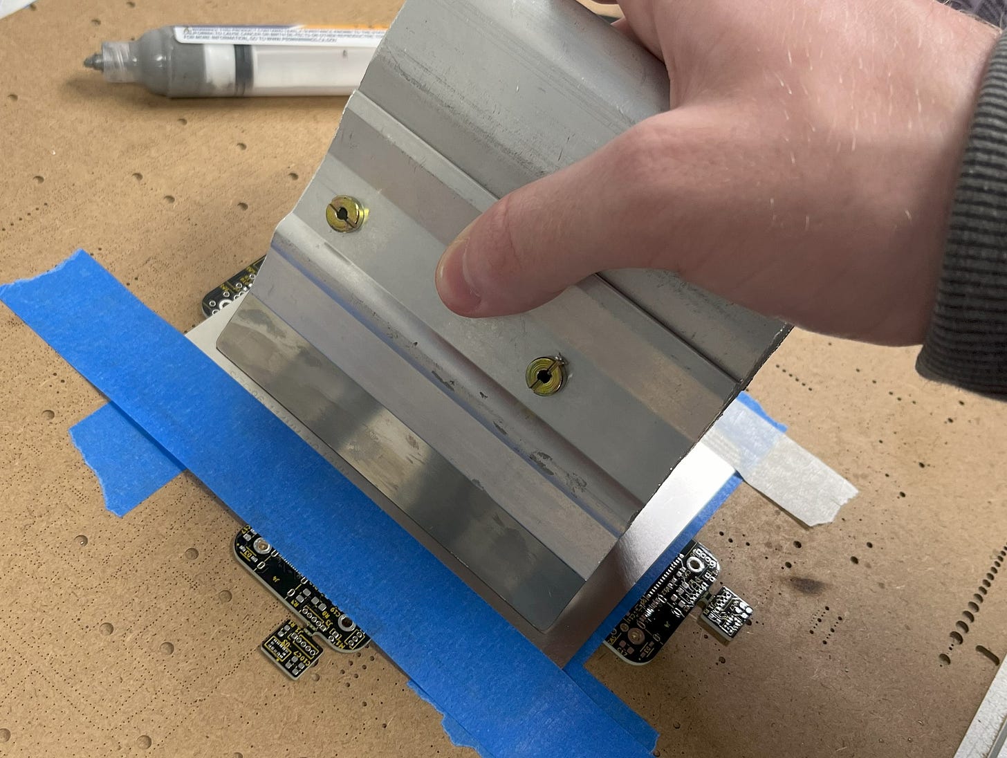
To build the board, first tape it down and apply solder paste using the stencil.
You should then have a nice layer of solder paste over all the component pads.
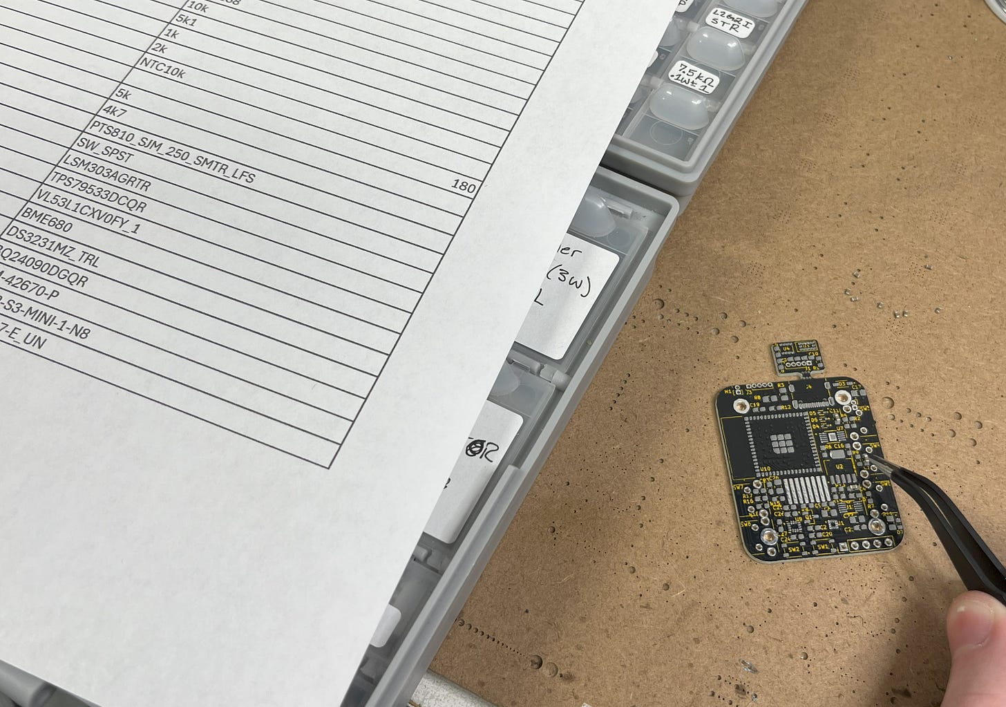
With that, start placing the components in collaboration with the reference sheet.
NOTE: Only place the LSM303AGRTR (U1) if you plan to implement it on your own. I placed it as an example, but it does not have any support in the programming. This said, placing the component will do nothing but eat up the battery unless you plan to implement it separately.
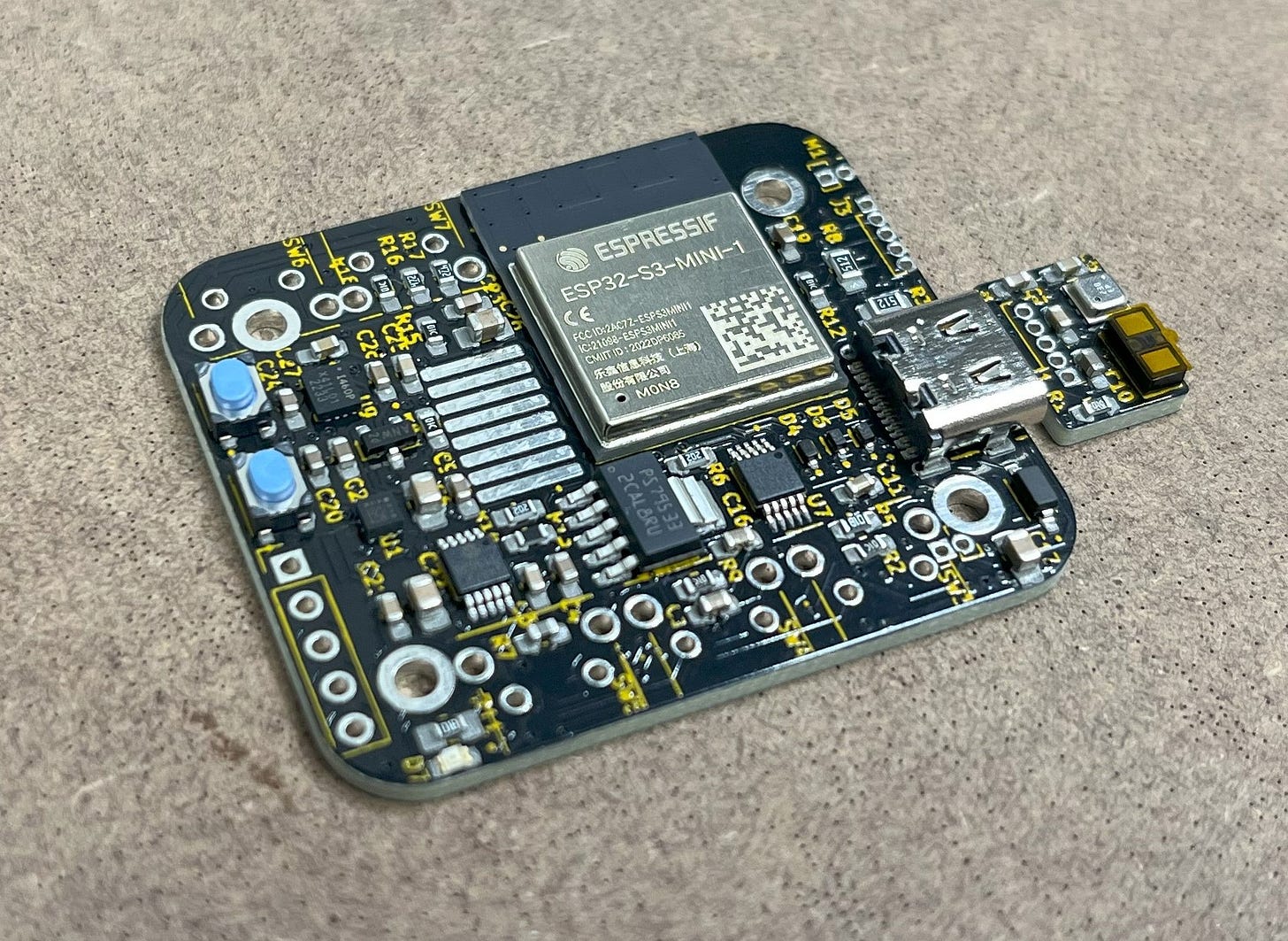
You should then have a really nice-looking board!
*I added U1 in this pic but you probably shouldn’t.
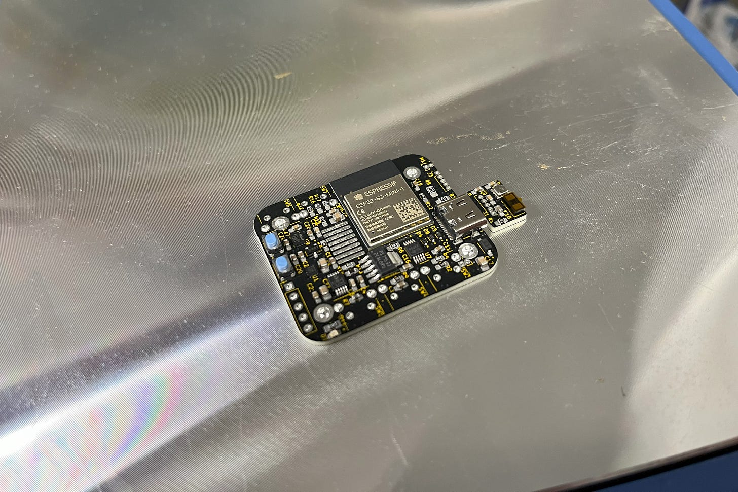
Next, carefully place the board on your hotplate and turn it on to melt the solder paste.
Beautiful!
Of course, this is not the finished product but is the mostly finished PCB. I’ll go over the rest in the Assembly section below.
Assembly
Here is the rest of the watch assembly.
The STL 3D printer files can be found here for free on my Thingiverse!
If you’re interested in also obtaining the logo-less STL files, door locker CAD, light switcher CAD, and all the editable STEP files, please consider becoming a paid subscriber! I don’t use ads, so I rely on your support! Plus, it’s only $5 and you will receive the following benefits. Already a paid subscriber? Access your materials here!
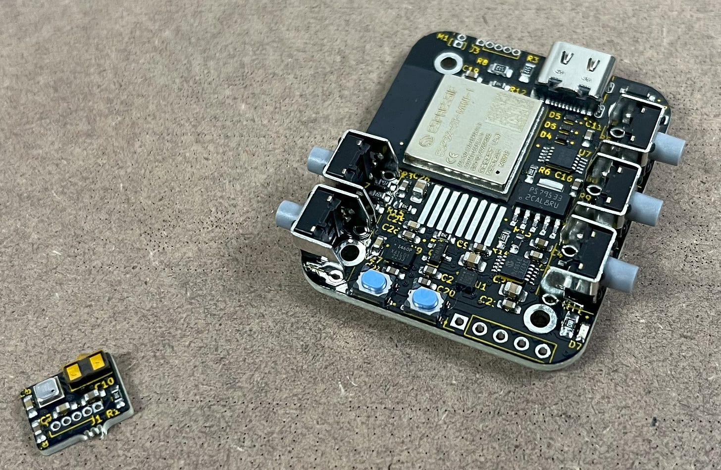
With the PCB done, break off the top mouse bites with the LiDAR and BME680.
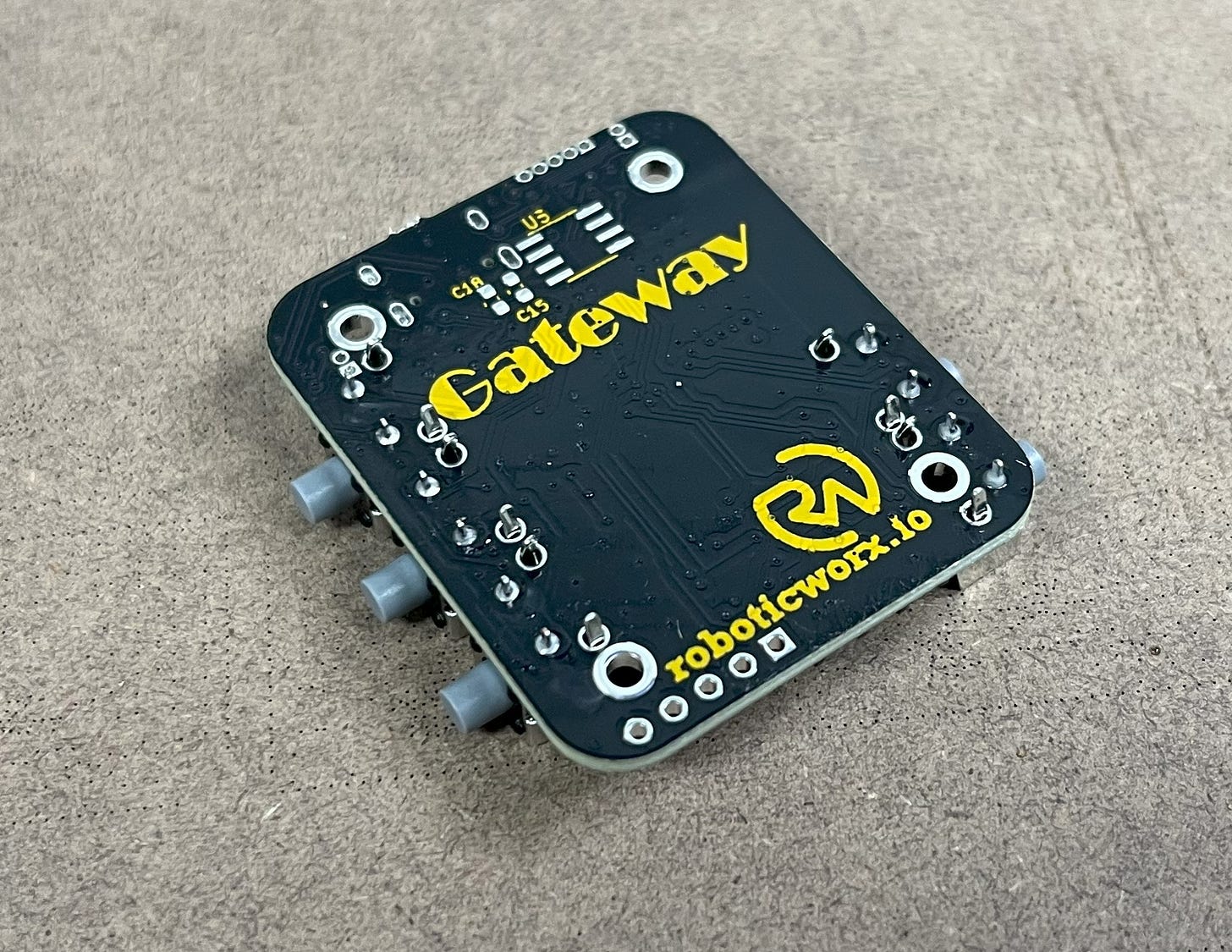
Then, pop in the buttons and flip the board over.
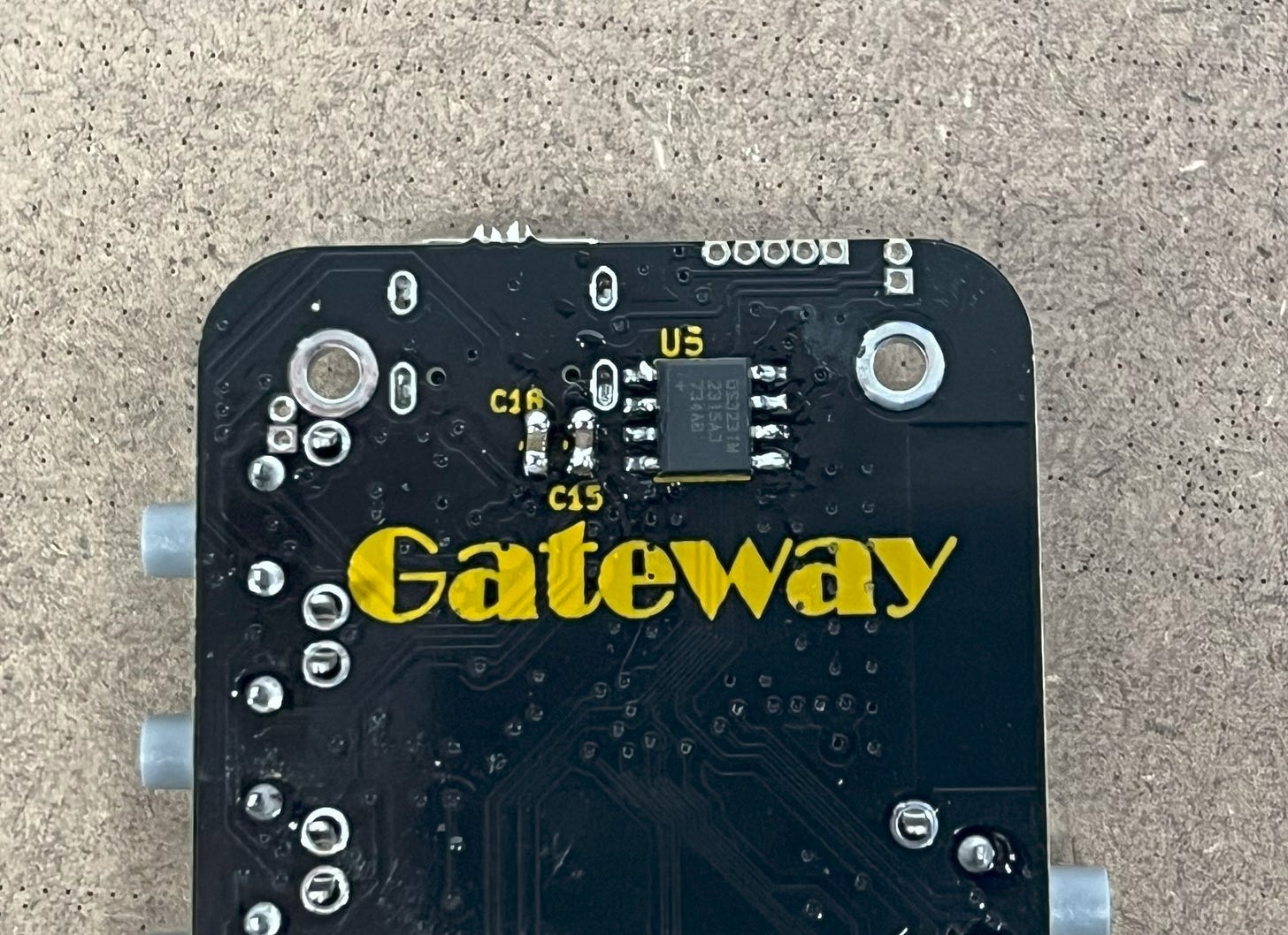
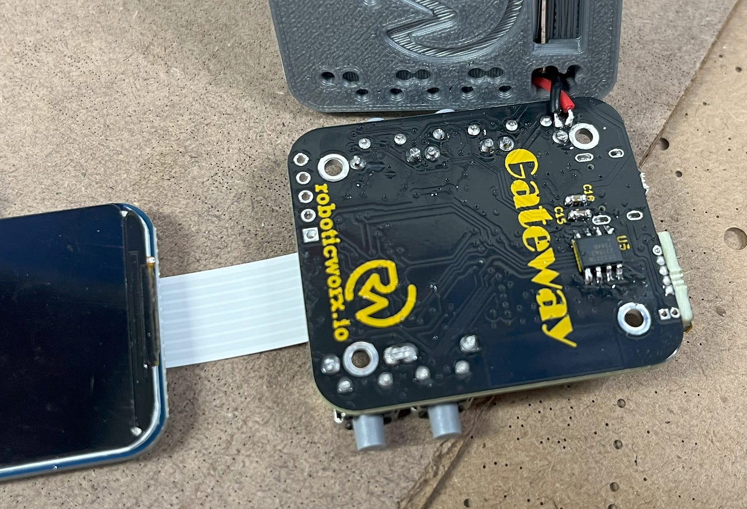
Here, you can hand-solder on the DS3231 RTC IC as well as C15 and C18. It may not be very pretty, but that’s okay: no one will ever see it again.
After that, you can also go ahead and solder the buttons too.
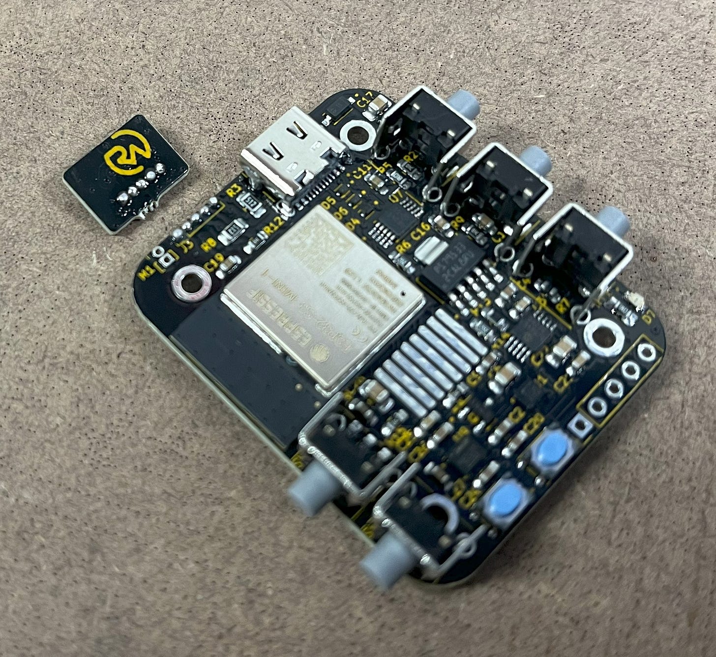
Then, grab your top half piece (LiDAR and BME680) and dab some solder onto it. You should also put some solder along the pin headers on the top of the main PCB. This will make it easier to connect them up.
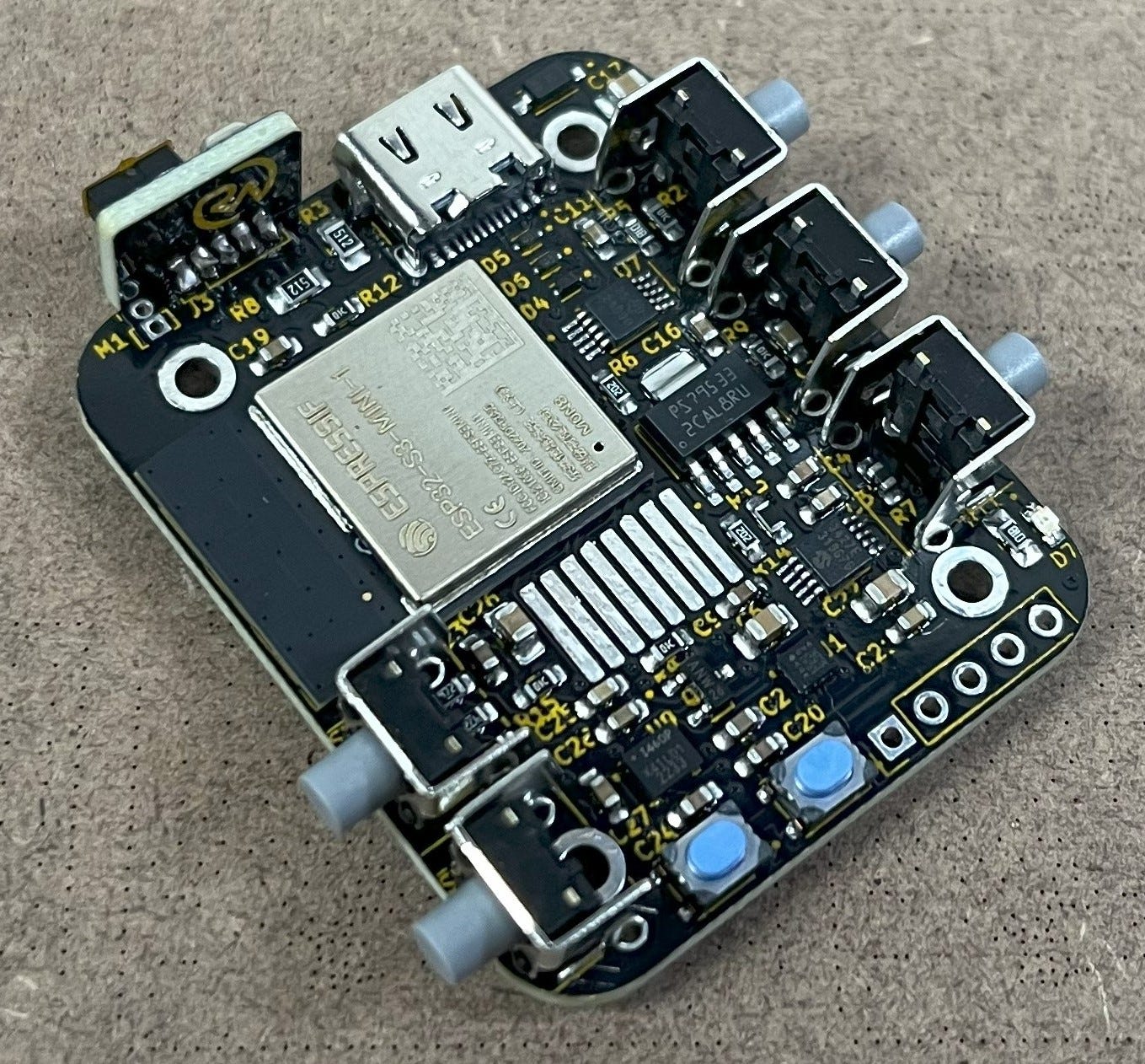
With that, hold the top half piece up as well as you can and melt the two solder blobs together. I recommend only doing one first and then adjusting it until you’re happy. Ideally, the top half should be 90 degrees to the PCB and flush against it. When that is the case, you can melt the rest together.
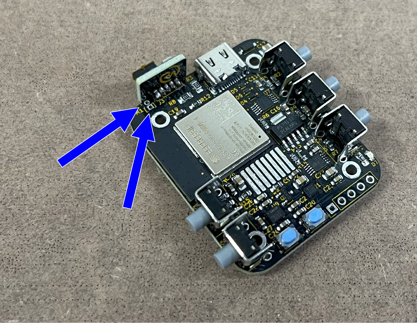
I also recommend pre-soldering the two M1 headers. This will make it easier to attach the laser pointer module later.
Just melt some solder on the two similar to what you did for J3. (This is not done yet in the photo.)
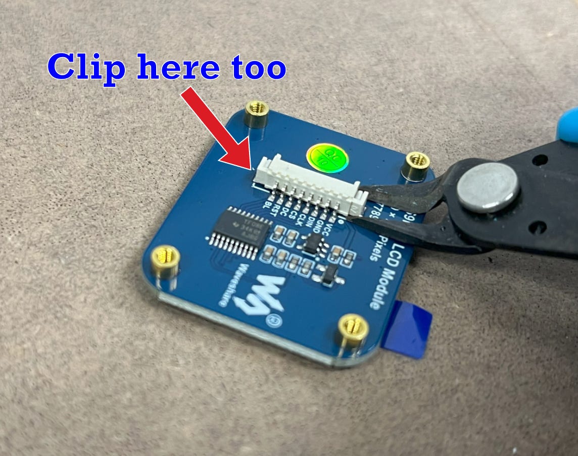
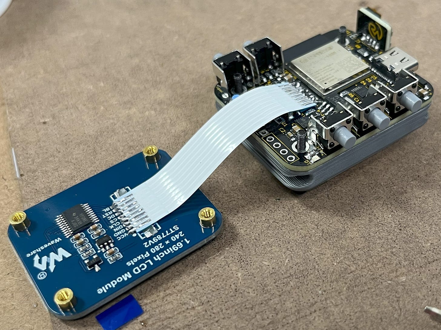
Awesome! Now we can work on readying the display. First, grab it and clip the two supports. Be careful not to clip it too close to the board, since you don’t want to accidentally break a trace.
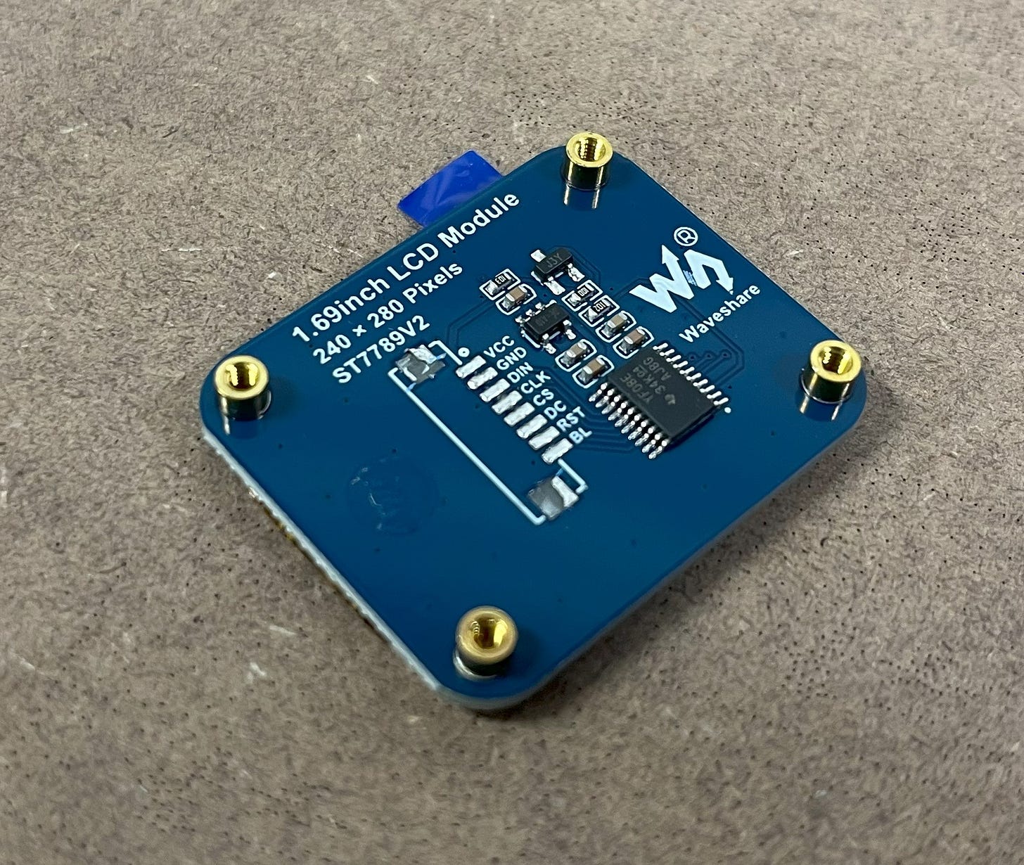
After that, you can use a hot air gun or similar to remove the rest of the connector.
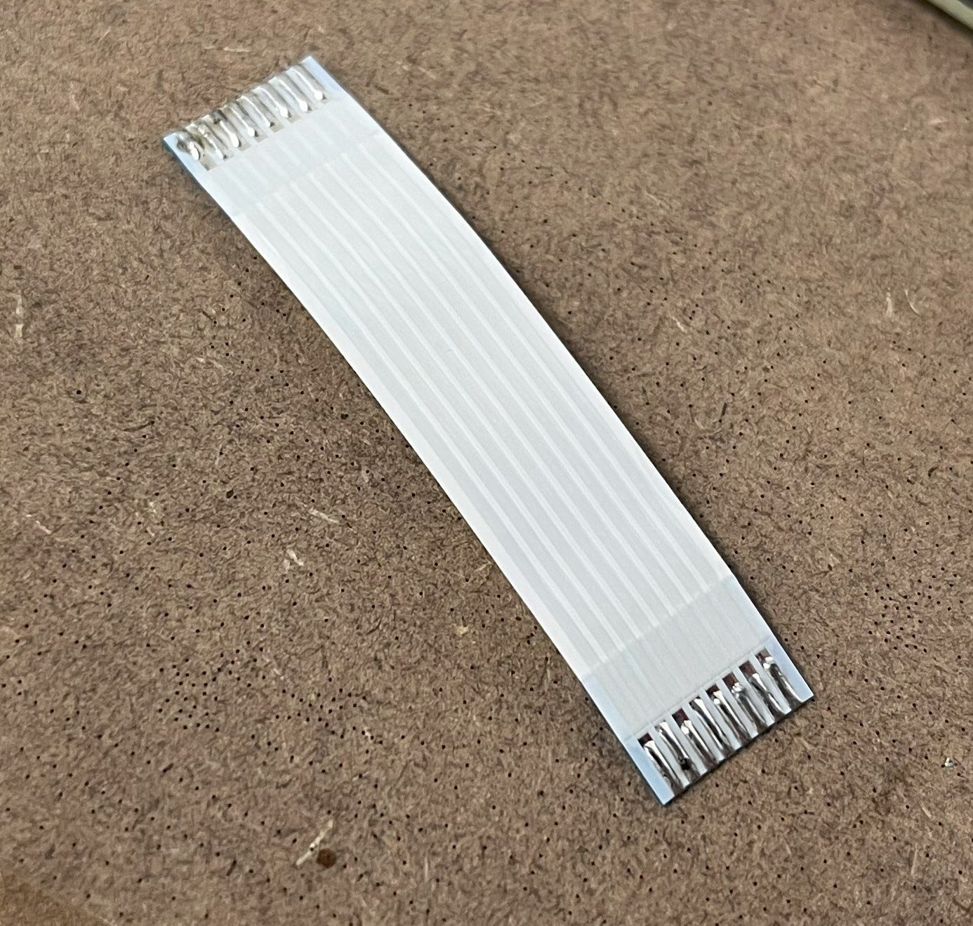
Then, grab your FFC cable (in BOM) and pre-solder the ends.
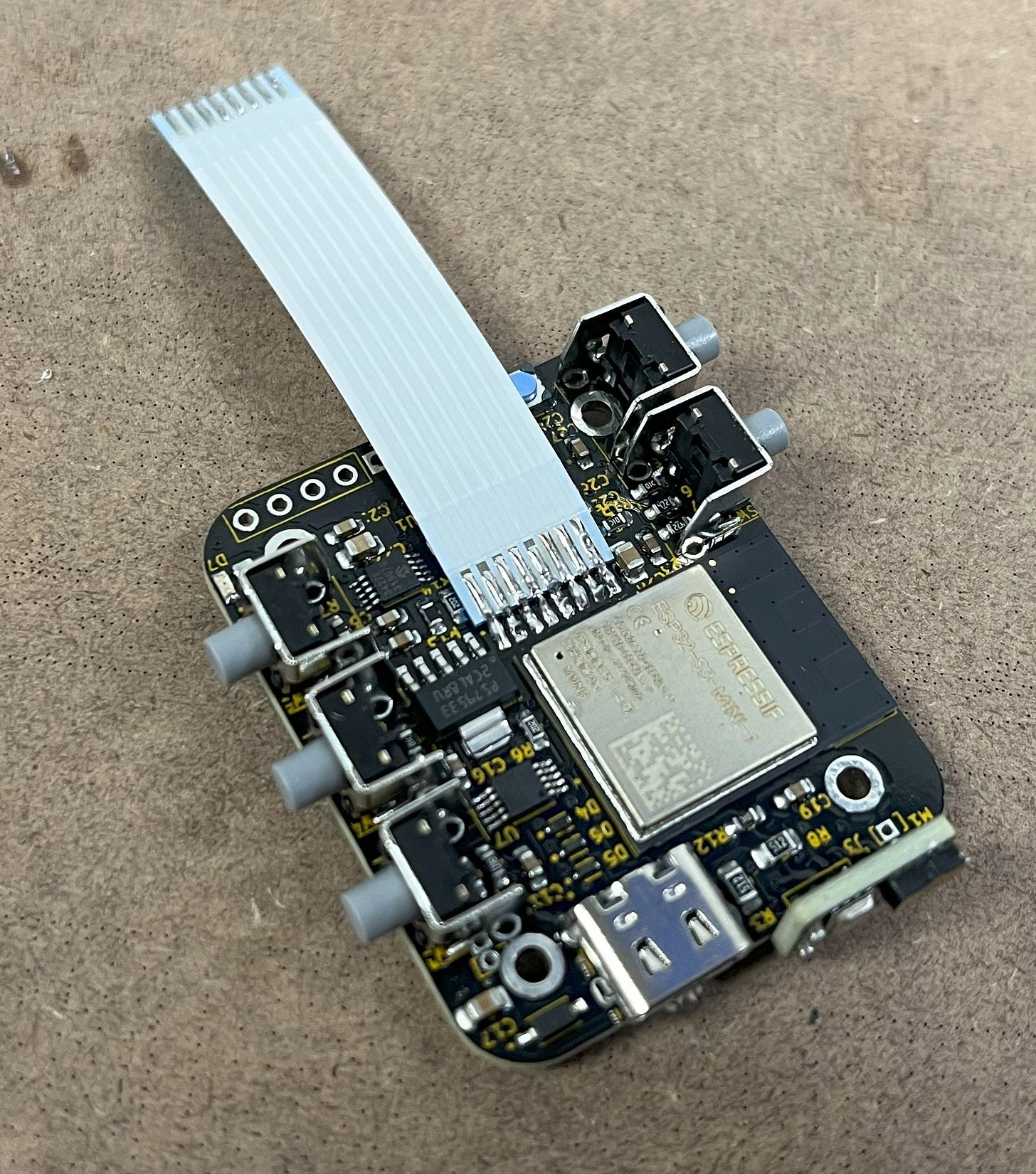
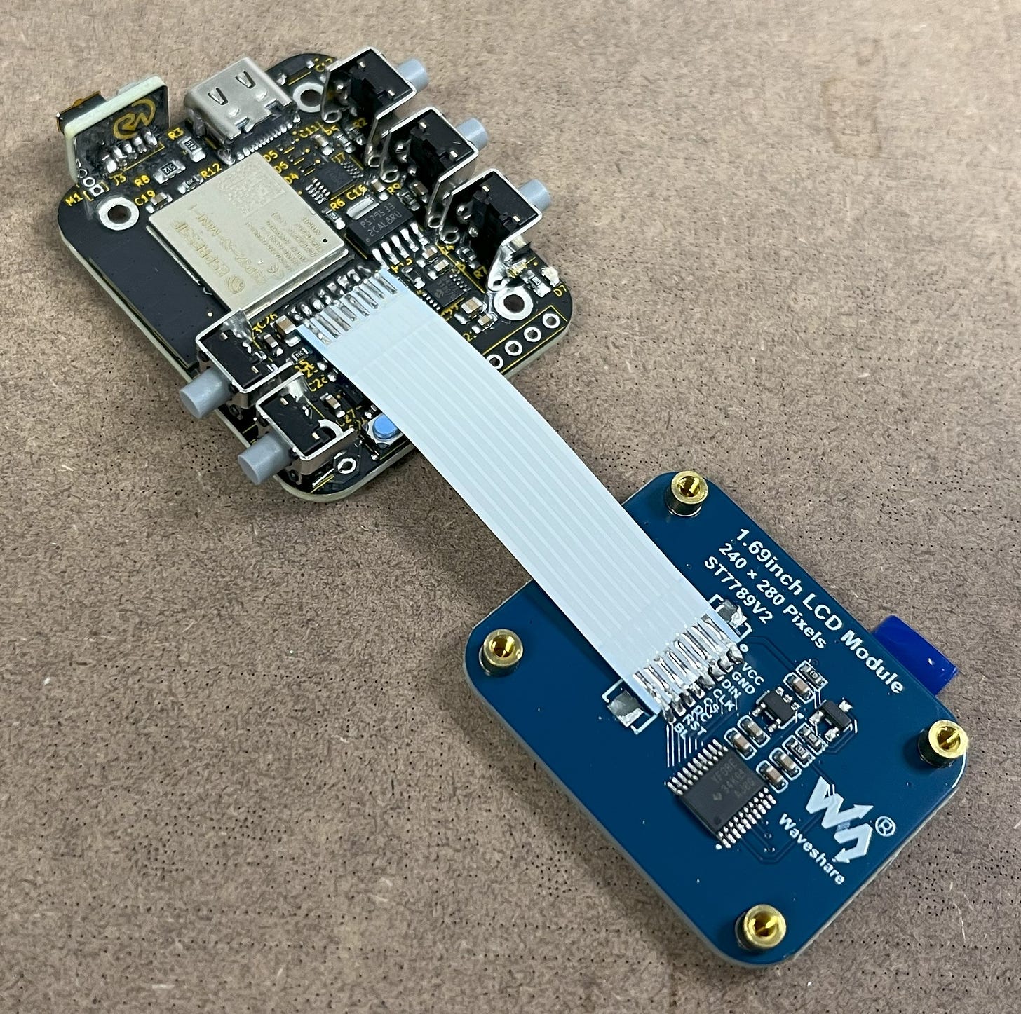
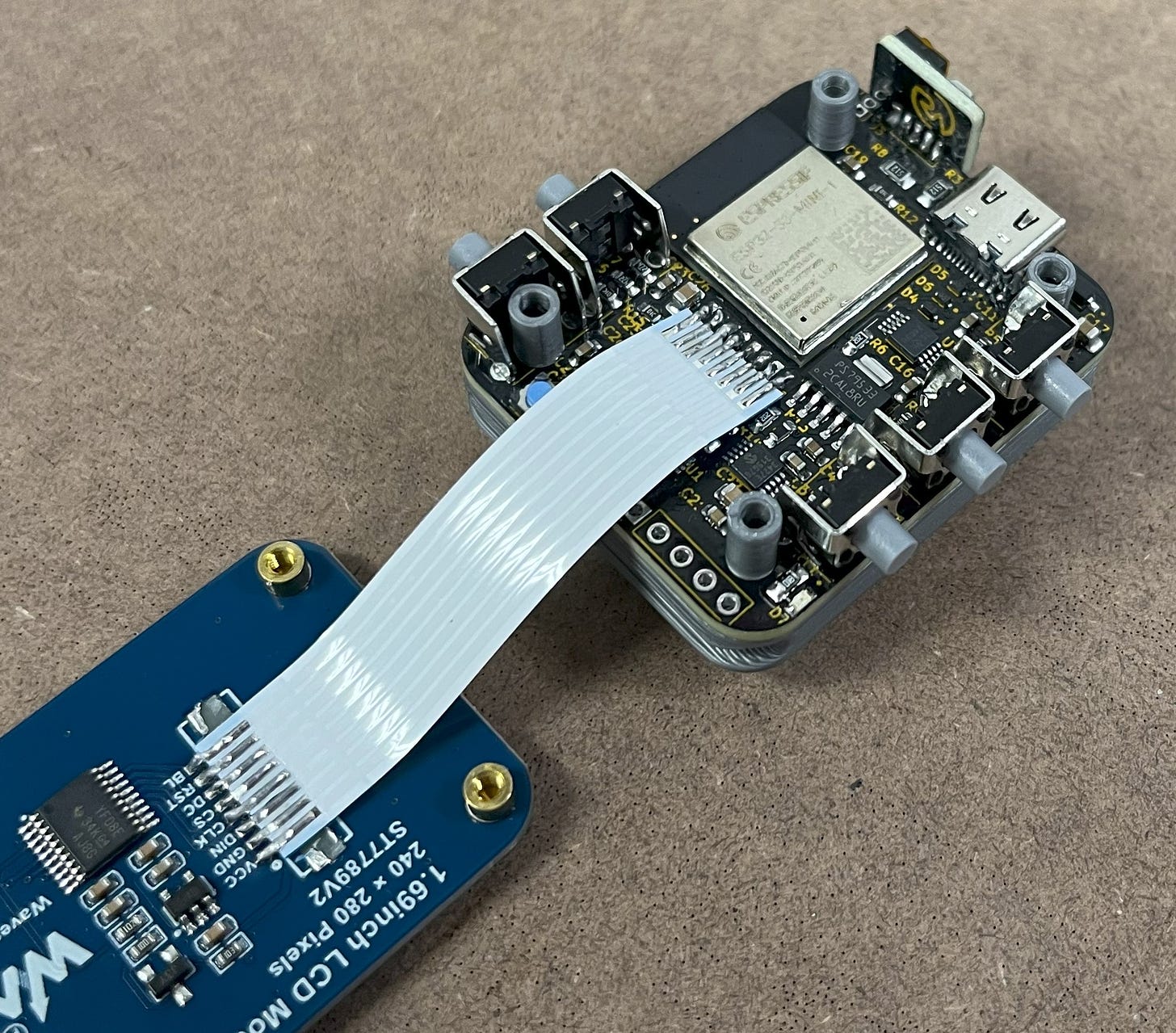
You can then connect it to the main PCB. To do this, I recommend laying the FFC cable flat against the board, putting a little solder on your iron tip, and then bridging it to the pad. I found it best to do this one at a time.
Now, you can do the same with the screen.
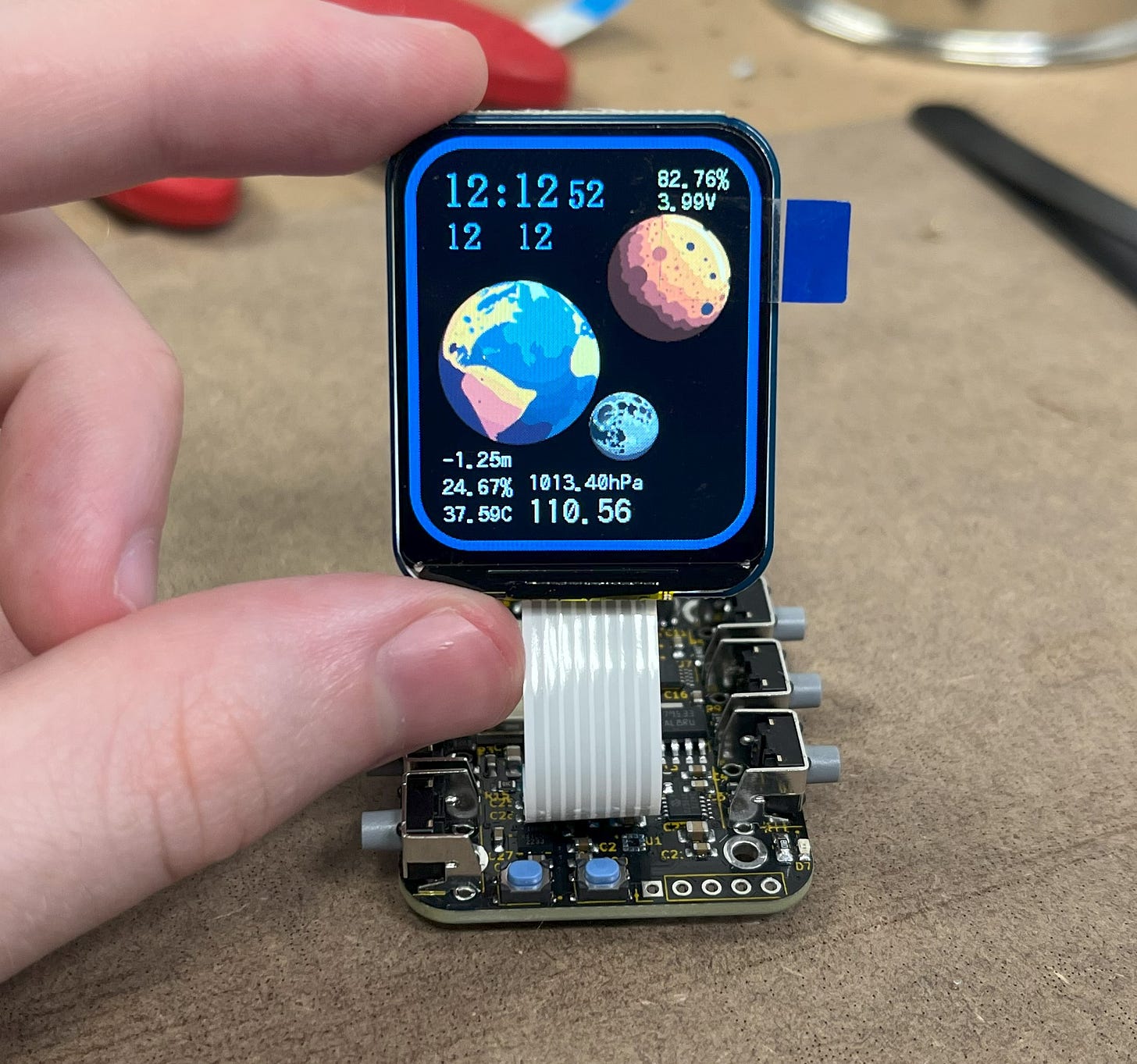
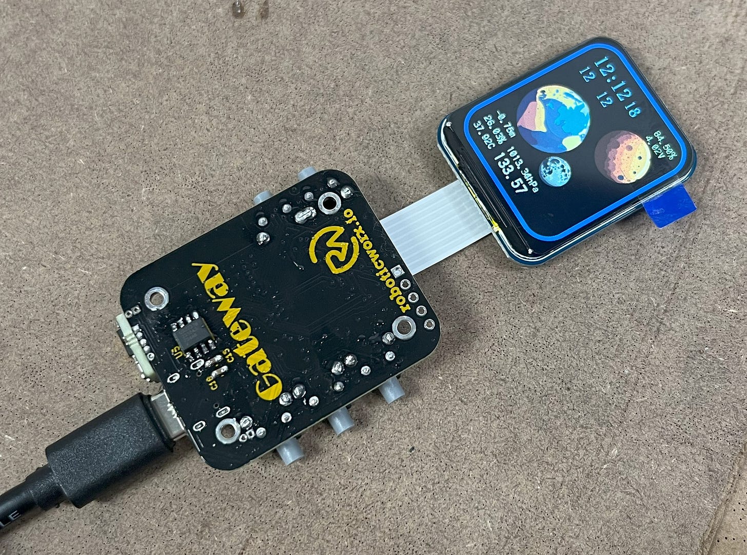
To ensure everything is working correctly, this is an easy time to test the PCB. Upload the main program via the USB-C port and make sure that everything looks good. Instructions to upload to the board can be found in the programming section.
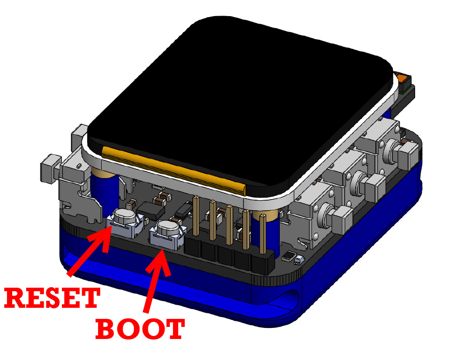
If after uploading the program you see that the screen doesn’t seem to be responding, just give it some time to cool down (with removed power) and try again. You can also try hitting the reset button (left-most button) and cycling power to the board. This should resolve it.
*What it should look like (with theme 2).
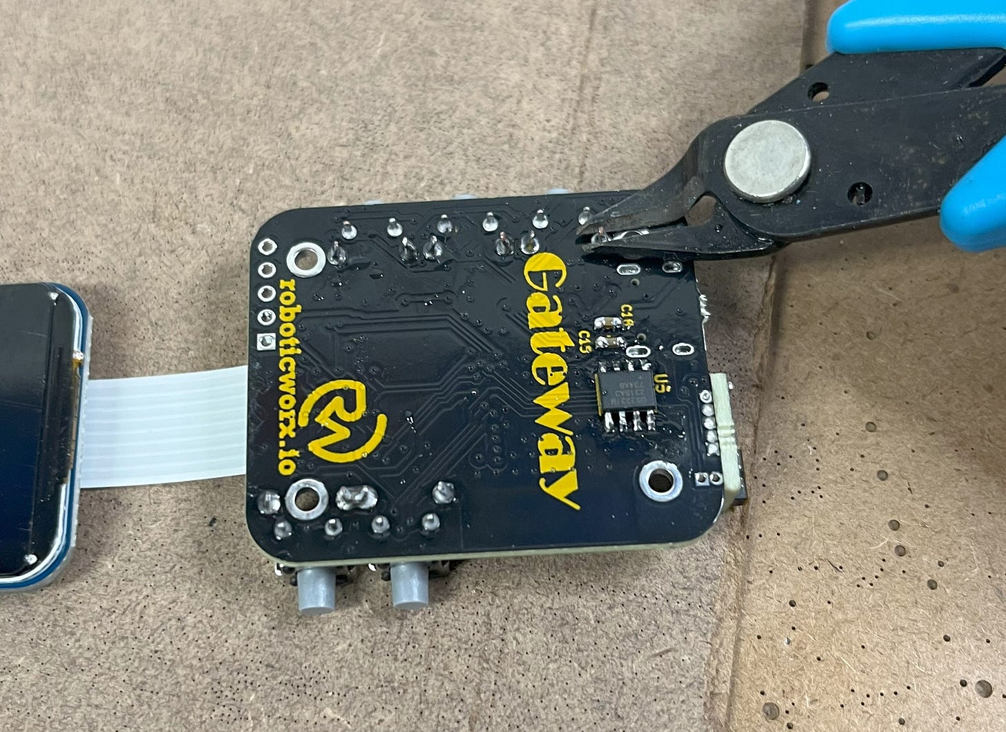
With that, you can go ahead and trim the button ends on the bottom of the PCB. This will help with fitting.
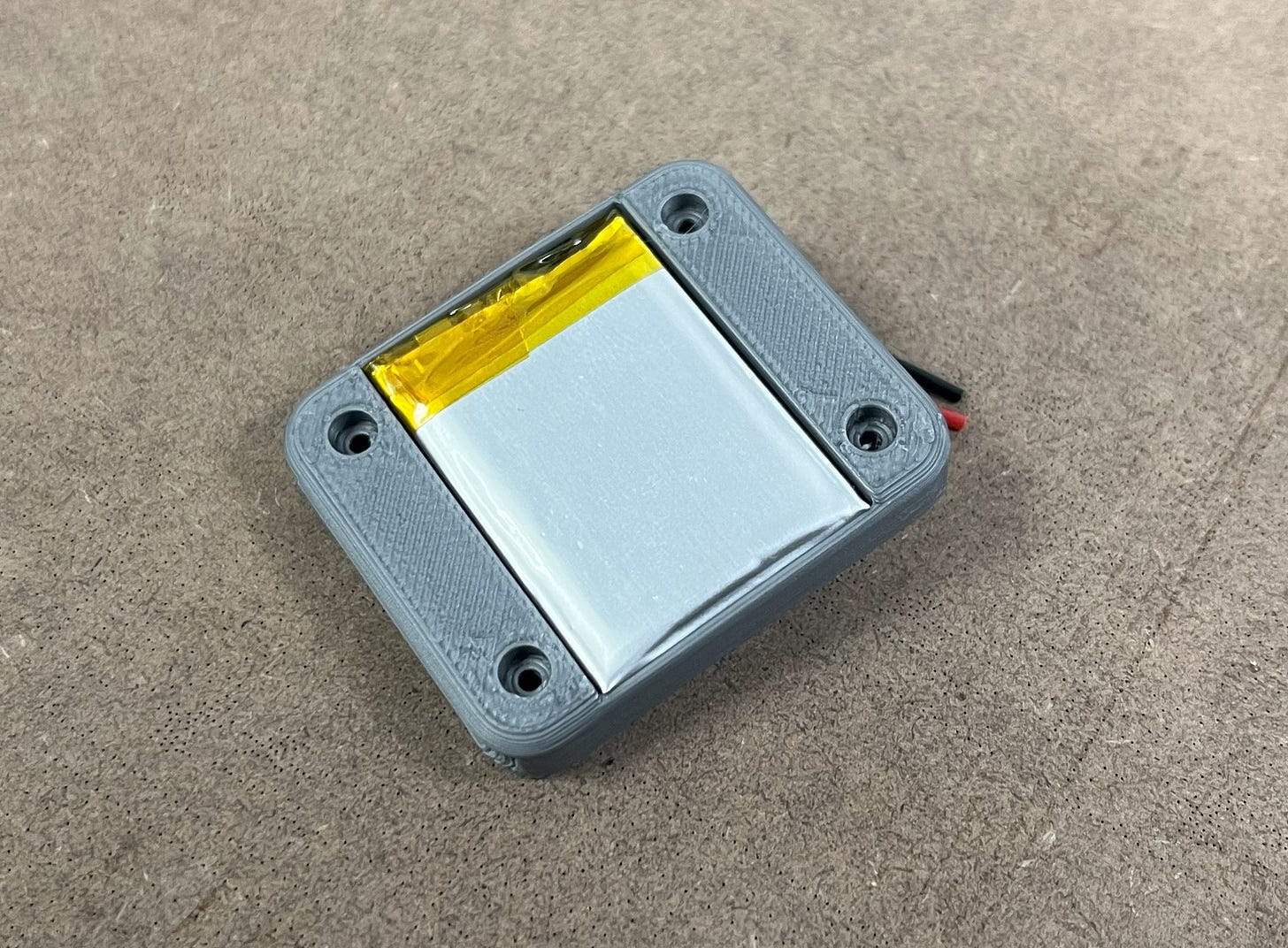
After that, grab your 3D-printed casing (files linked in BOM) and slide in the 400mAh LiPo battery.
Note: For some reason, the manufacturer of this battery seems to be sending them in two different sizes (one is a few millimeters longer than the other). This isn’t an issue, but it should be noted that because of this there are two versions of the base watch CAD on my Thingiverse page.
Logo-less STL files are available here to $5 paid subscribers.
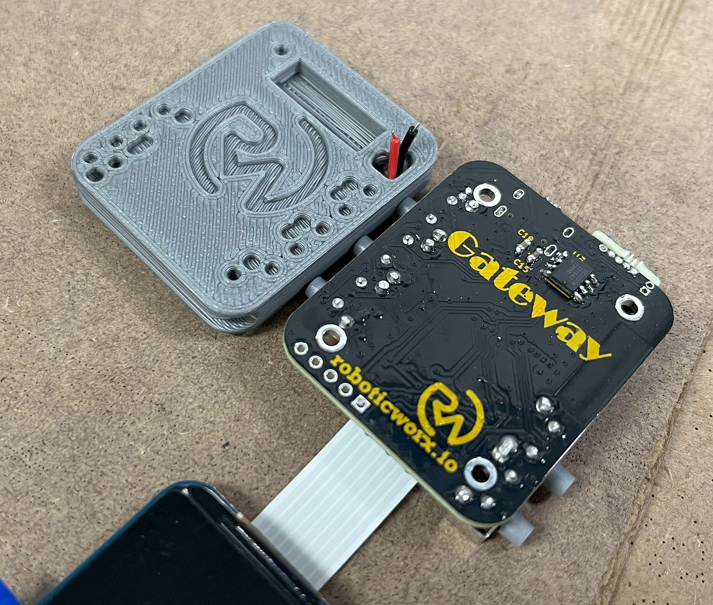
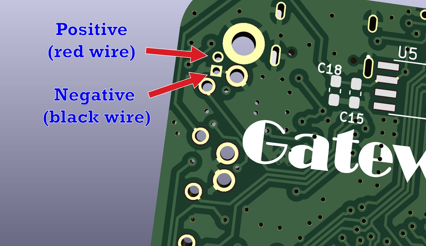
Then, trim the ends down a bit and apply some solder to the wire and the battery terminal connectors (positive and negative) on the back of the board.
*On the back of the PCB.
Next, make the connection. I recommend soldering the ground (black) wire on first since it takes longer to heat up.
NOTE: If the screen doesn’t seem to be turning on after soldering the battery connectors, plug in the charging cable to fix it. I believe it’s a security mechanism of the LiPo since it was getting rapid inrush currents when making the connection. By charging the battery, you reset it. You may also need to do this after soldering the laser module to the PCB.
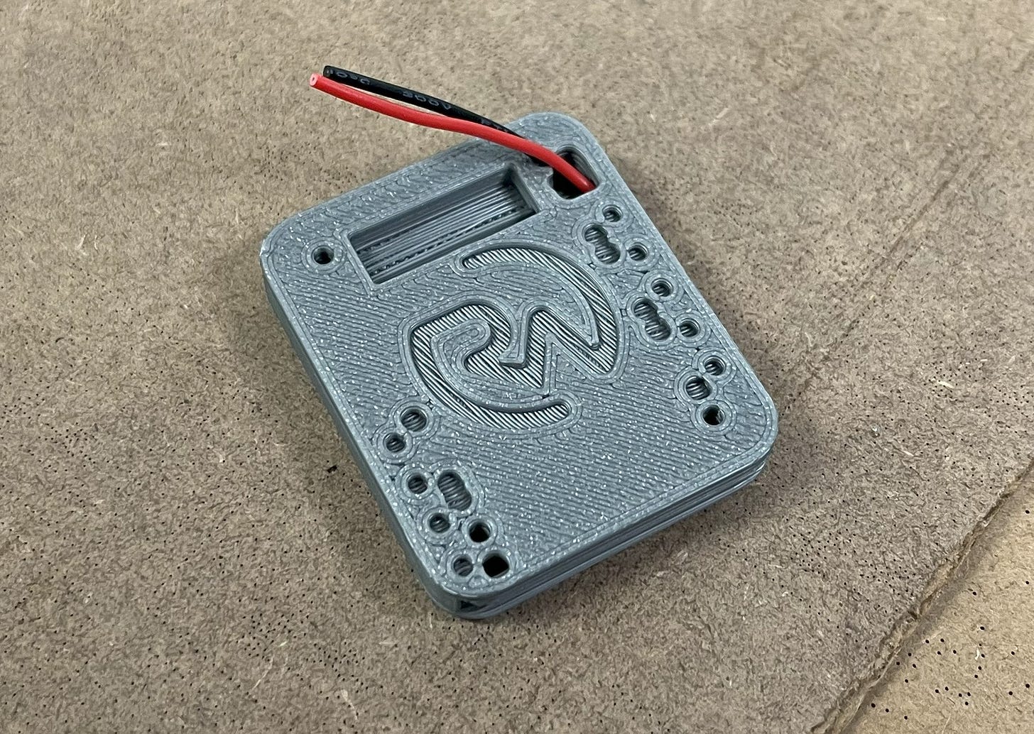
With that, stuff the 3D-printed casing over it. It may not be a perfect fit, but it’ll work if you push it down some.
Awesome! You can also go ahead and slightly screw in some M2x16mm bolts. Just be sure not to screw them in all the way, they should only be sticking out ~6mm past the PCB on the top.
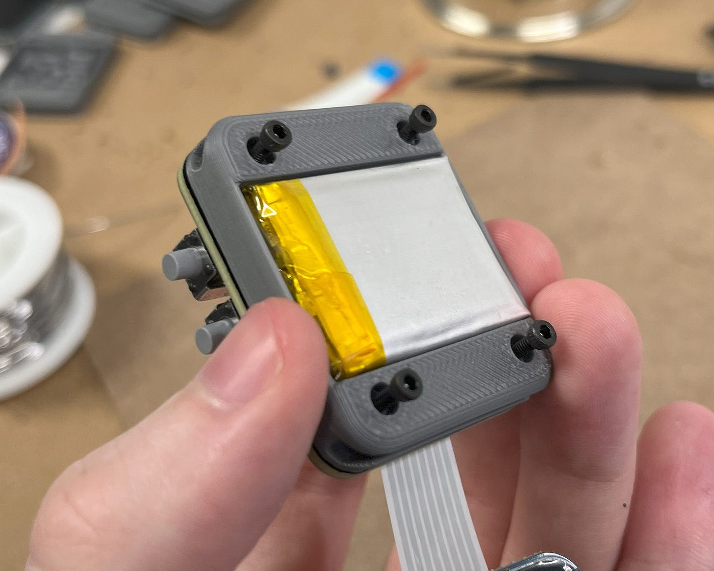
Continued...
After that, grab your 3D-printed spacers (also linked in BOM) and place them over the exposed bolt ends.
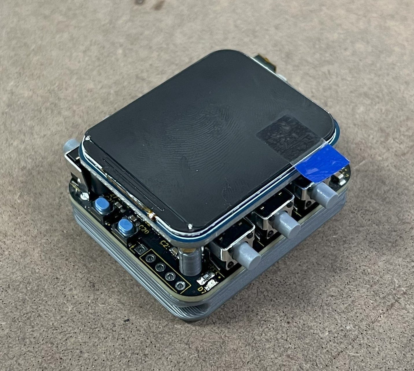
Then, tuck in the FFC cable and line up the display over the PCB. It should be noted there will probably be some small protectors over each screw insert on the back of the display, these should be removed. When that’s done you can finish screwing in the bolts.
*Don’t mind the fingerprint haha.
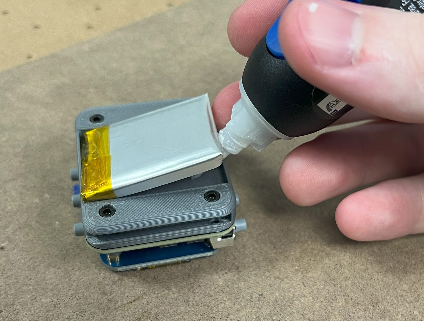
Next, flip it back over and lift up the battery with some tweezers or similar. This way you can put some super glue on the bottom to ensure the battery stays in place. This is being done now so that the battery can be removable up to this point in case a mistake was made.
Almost done!
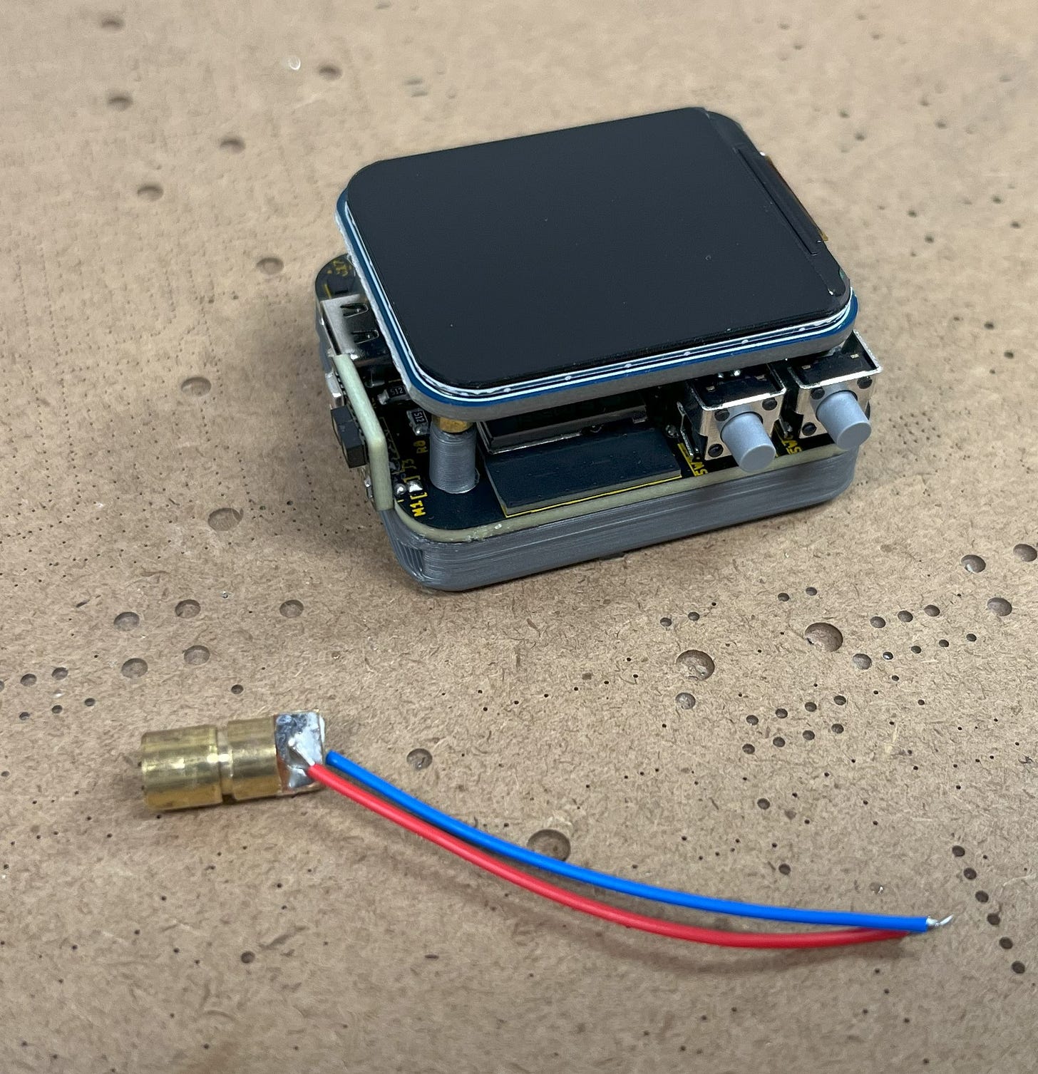
With that, grab a laser module and cut it around halfway. Then, pre-solder the wire ends some. This will make the connection easier.
Afterward, push the wire end under the screen but behind the support.
Then, solder each to a M1 header.
Now, twist the laser module a few times to help with wire management, and then grab your trusty super glue again. You’ll want to place the glue on the PCB under where the laser module will go. You’ll also want to do your best to align the laser module so that it is pointing straight-forward and flush with the side of the ESP32-S3-MINI antenna. The better this is done, the better the accuracy of the laser dot to the actual measuring location.
With that, remove the film protector over the LCD screen and LiDAR and you’re done!
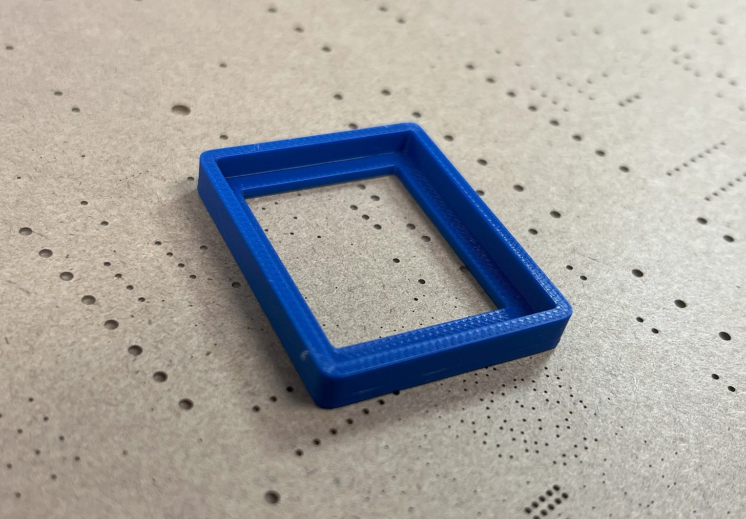
If you’d also like to add the glass screen protector over the watch LCD, first, print out the screen alignment guide (linked in BOM).
Then, place it over the watch screen. Feel free to clean the screen before doing this if you have been using it previously.
Next, peel off the screen protector film and align it to the guide. Then give it a firm push in the middle.
You can then remove the guide. Viola!
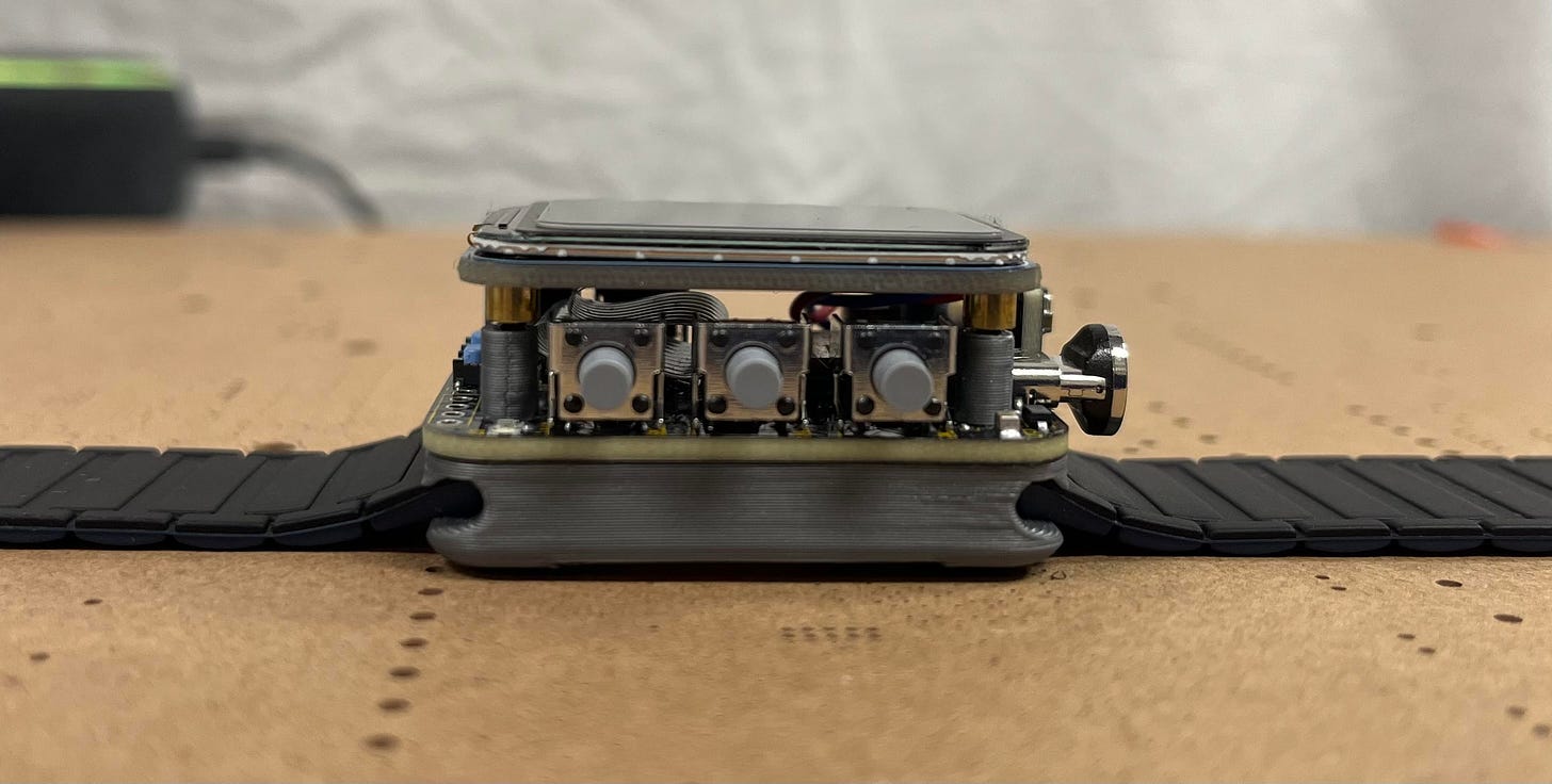
To insert the watch band (options linked in BOM) just slide them into the exposed side. It may be a tight fit but this is intentional to ensure they don’t fall off at a later time.
I’ve personally really liked the magnetic band but other options are fine too.
With this last step, you’re done! Enjoy your cool new watch! :)
Having an issue with a certain step or other? Leave a comment letting me know and I will do my best to help troubleshoot.
NOTE: The screen is fragile so if it ever breaks, just unscrew the bolts and desolder the part of the FFC cable that connects to the screen. Then, order a new screen and solder the cable back after removing the connector that it comes with (in assembly instructions). EZPZ!
Operating The Watch
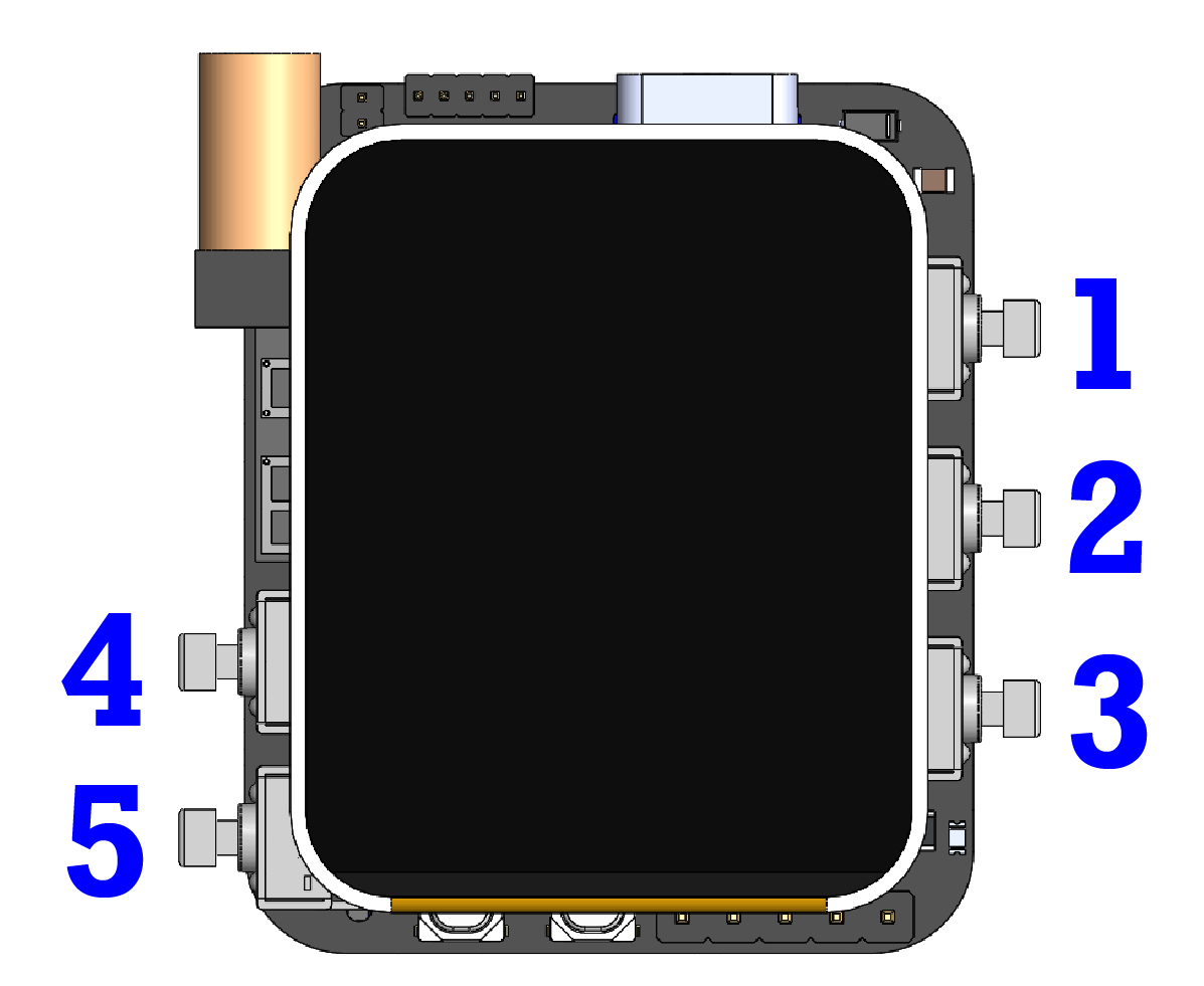
Being a pretty complex project, I thought it’d be a good idea to add a section about how to use the watch and operate the different buttons/combinations. Here’s the general button layout and what they do:
Buttons:
- Button 1 is your all-purpose home button. At any point when this button is clicked, you will return to the home watch face where the watch is able to enter sleep mode (enables the 1.5-second timer). This button also wakes up the watch (in addition to tilt-to-wake) if it was previously in sleep mode.
- Button 2 puts the watch in its wireless mode. From there, buttons 2-5 are reassigned to help navigate the different MAC addresses. Button 3 switches through the MAC addresses, button 4 changes the MAC address digit selected, and button 5 iterates through the digits of the currently selected MAC address. When you’ve changed the addresses to your liking, clicking button 2 on the currently selected address sends a 1 to it wirelessly (this is the default for binary operations like lights on/off but it can be easily changed if you’d like). When all this is done, you can click button 1 to return to the home watch face and turn the other buttons back to their normal functions.
- Button 3 is the Inertial Measurement Unit (IMU) mode button. After clicking button 3, a menu will appear to show current gyroscopic and accelerative readings from the onboard ICM42670. These readings can be useful for slope detection and digital leveling as described earlier, with tilt readings from the accelerometer being converted to degrees (0-0 is flat). It may seem counter-intuitive that the “tilt” data is under the accelerometer readings and vice versa, but this is actually correct since the accelerometer measures the force of gravity acting on the device. If the device is tilted, the gravity component will be distributed among the different axes, which changes the tilt angle.
- Buttons 4 and 5 are special since they alone don’t do anything but contribute to combinations when being held. I’ll go over the combinations next, but it should also be noted that pressing them both down at the same time will put the watch in a “frozen” state. This only means the watch won’t be able to enter sleep mode until they’re both pressed again which can be useful when trying to read the watch’s environmental data.
Combinations:
- Holding button 4 and clicking button 1 will turn on the watch’s flashlight screen. All this means is that the watch screen will turn a bright white to help illuminate your surroundings; which is useful when it’s super dark and you can’t see much.
- Holding button 4 and clicking button 2 will notify the watch to start a WiFi scan. This will change the watch to a new blank screen where local 2.4GHz networks will appear a few seconds later. Network data will include the SSID (name), RSSI (signal strength), and Auth Mode (how secure the network is 0-7).
- Holding button 4 and clicking button 3 will put the watch in clock change mode. This is super useful since it allows you to update the current time without having to change anything in the program code. While in this mode, button 4 can be used to iterate through the time menu, and button 5 iterates the selected unit. When you’re done setting the time, go to the seconds unit (IMPORTANT) and then hold buttons 4 and 5 at the same time to update the current time. If you don’t want to update the time, you can also just press button 1 to return to the watch face.
- Button 5 combinations are unique since they all act as wireless hotkeys. This way, you don’t have to navigate to the wireless menu every time you want to send a wireless signal. Holding button 5 and clicking button 1 will send a 1 to the first MAC address in the menu, holding button 5 and clicking button 2 will send a 1 to the second MAC address in the menu, and so on up to three. It should be noted that the watch must be on for all of these to work except when sending data to the first MAC address (button 1 wakes it up).
- To activate the LiDAR, hold button 1 and press button 2. To activate the laser pointer, hold button 1 and press button 3. You can do the same combination for each to disable them.
If at any point something is going wrong, you can always click the hardware reset button found next to the boot button. This should resolve most problems. Just know that you will need to update the time as well as any MAC addresses.
If there is still a problem and the screen seemingly won’t turn on, etc., then one of the sensors may have crashed leading to broken code. If this happens, let the watch battery die (don’t use it for a day) and then plug it back in later. This will reset the sensors. If this still doesn’t work, let the watch battery die again and let it sit for longer.
Programming
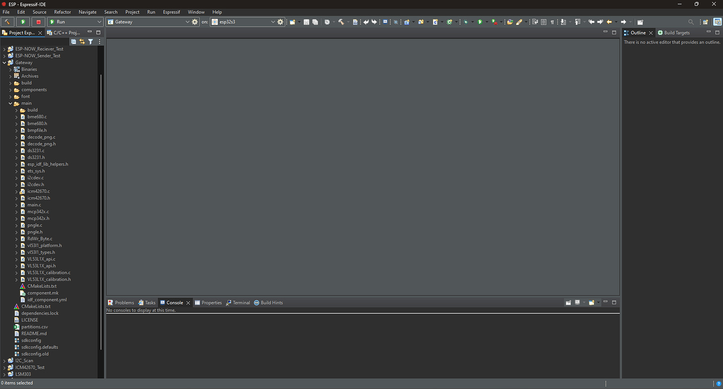
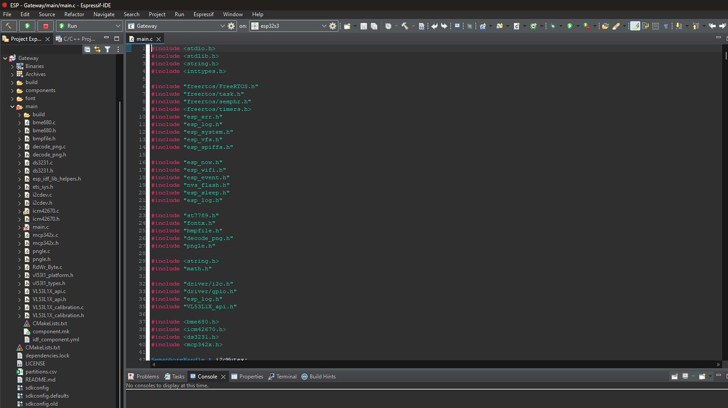
Contrary to my typical method of programming, this project was too complex to properly write in the Arduino IDE. I’ve been looking for an excuse for a while now to step up my programming game by moving to ESP-IDF (the official IoT development framework for ESP32 microcontrollers) and I thought this would be the perfect project for it! By migrating to ESP-IDF, I get to utilize FreeRTOS (a real-time operating system for robotics and electronics on a commercial level) in addition to more advanced features so I can have complete control over the MCU.
*Espressif-IDE in night mode.
Since I know many of you have probably never used ESP-IDF before (like me before this project), I wrote another entire article about installing it and the basics of how it works which is available here for free.
This took a while, show your support by subscribing (it's free)!
Subscribed
Since the code for this project is quite extensive, I unfortunately will not be going over every line like I usually do. However, to make up for it, the full code is posted in its entirety on my GitHub page. If you have any additional questions about the programming or ideas for improving the code (I’m sure it’s not perfect), I’d be happy to answer them in the comments! You can also find a basic Arduino-Gateway receiver sketch here.
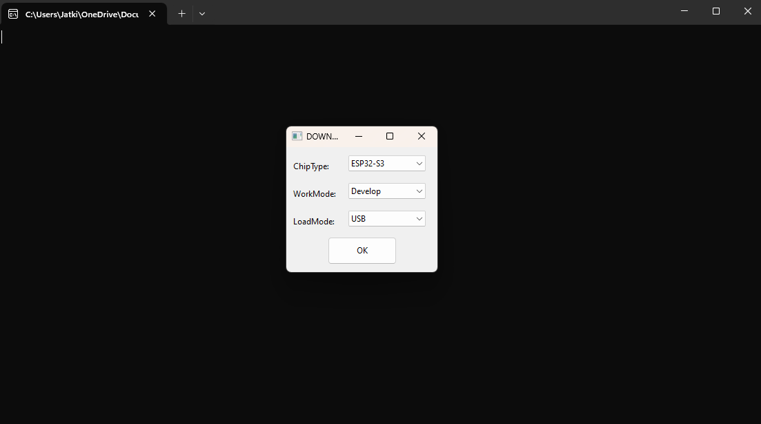
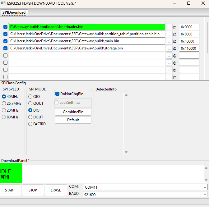
If you’re not interested in editing any code, you can also program the board easily through this online flasher which doesn’t require any ESP-IDF installation. All you need to do is go here and download Espressif’s latest Flash downloader tool.
Then, click on the executable (.exe) file and enter the chip information.
After that, download these four prebuilt files:
- bootloader.bin
- partition-table.bin
- main.bin
- storage.bin
Which are available in either:
- Steampunk theme (click to go to the download page)
- Planets theme (click to go to the download page)
Note: There are two versions of the main.bin file for each. One is 24 hour time and the other is 12 hour time. You can pick the one you prefer.
When that’s done, select each file from your computer and assign them to the given addresses on the right (0x0000, 0x8000, 0x10000, and 0x110000). Ensure the same address is lined up with the corresponding file like in the image below.
NOTE: Make sure each file is selected by clicking the check mark to the left of it. Also, before uploading any code (flasher tool or otherwise), you must put the board into bootloader mode. You can do this by holding the boot button (right-most button) > clicking the reset button (left-most button) > and then releasing the boot button.
Next, plug in the board and select the corresponding COM port in the bottom right. Afterward, click “START” and wait for the green bar to fill. When it’s done flashing, reset the board and you’re done!
Curious how I knew what bin files and addresses were needed? In the build folder of all ESP-IDF projects is a file named “flash_args” which contains the names of the necessary bin files and the address where they should be flashed.
Custom Watch Themes and Colors
If the default watch themes I made aren’t quite your thing, you’re in luck! The watch screens are just decoded PNG images and can be easily switched out and customized to your liking. Here’s how!
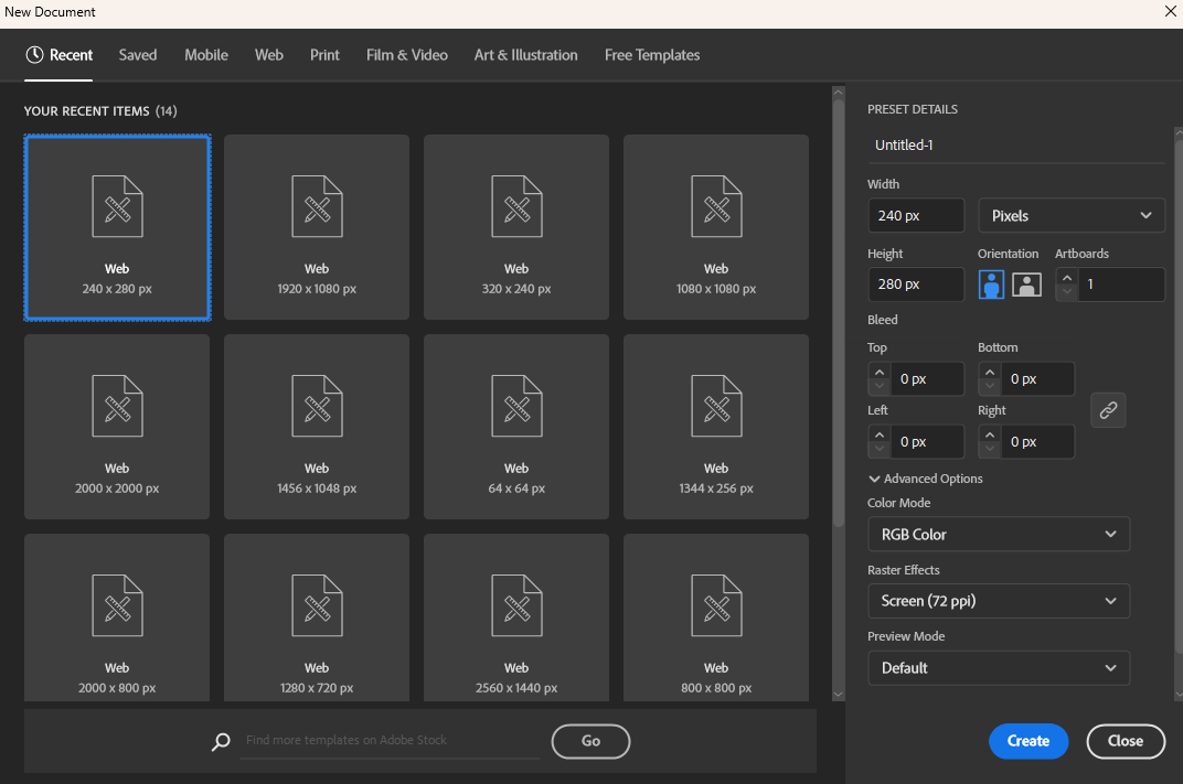
First, open up some sort of image design software or pick out some pictures that you like online. Then, map it to a 240x280 pixel workspace. In my case, I’m using Adobe Illustrator for this.
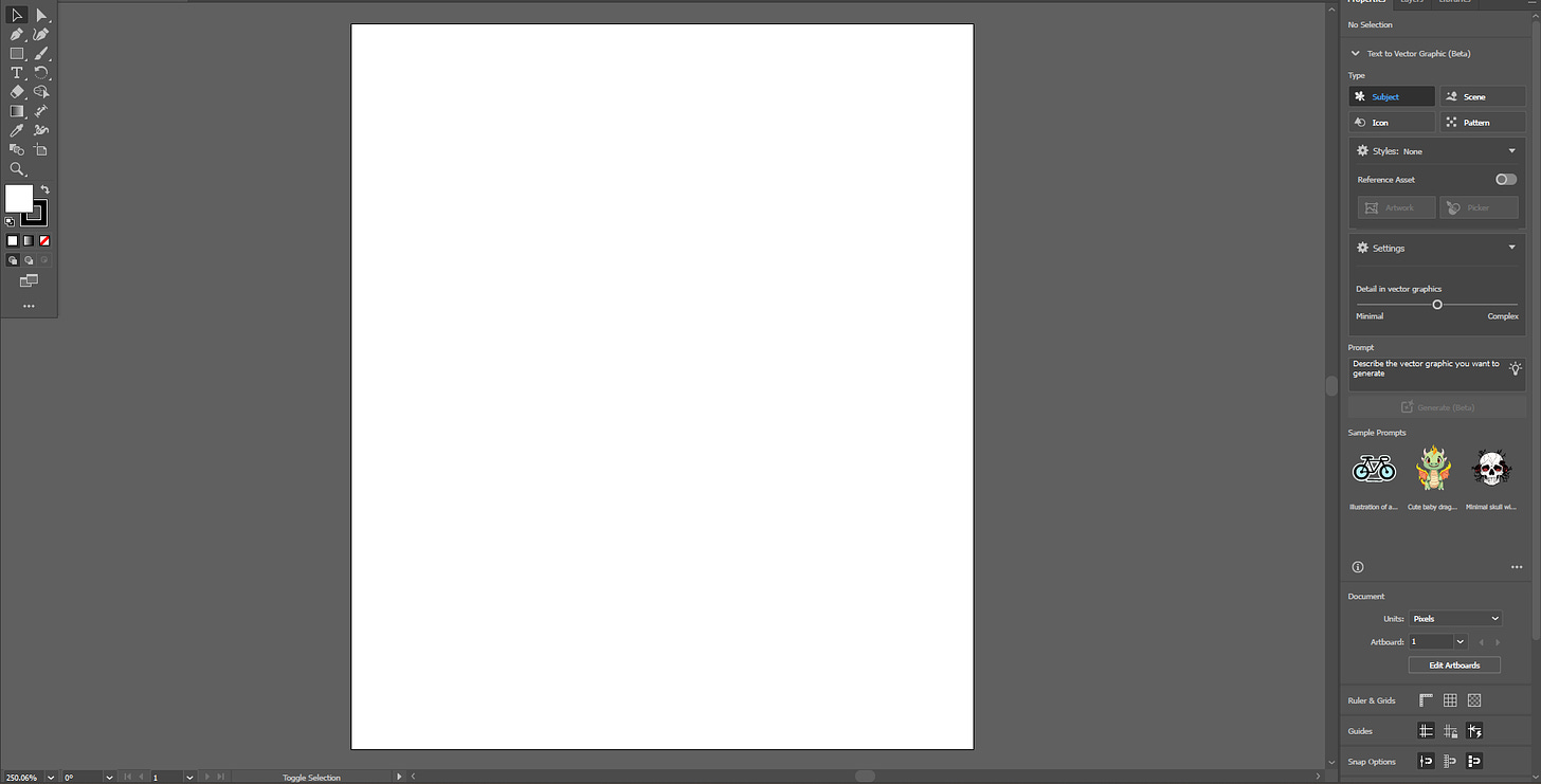
You should then have a nice blank canvas.
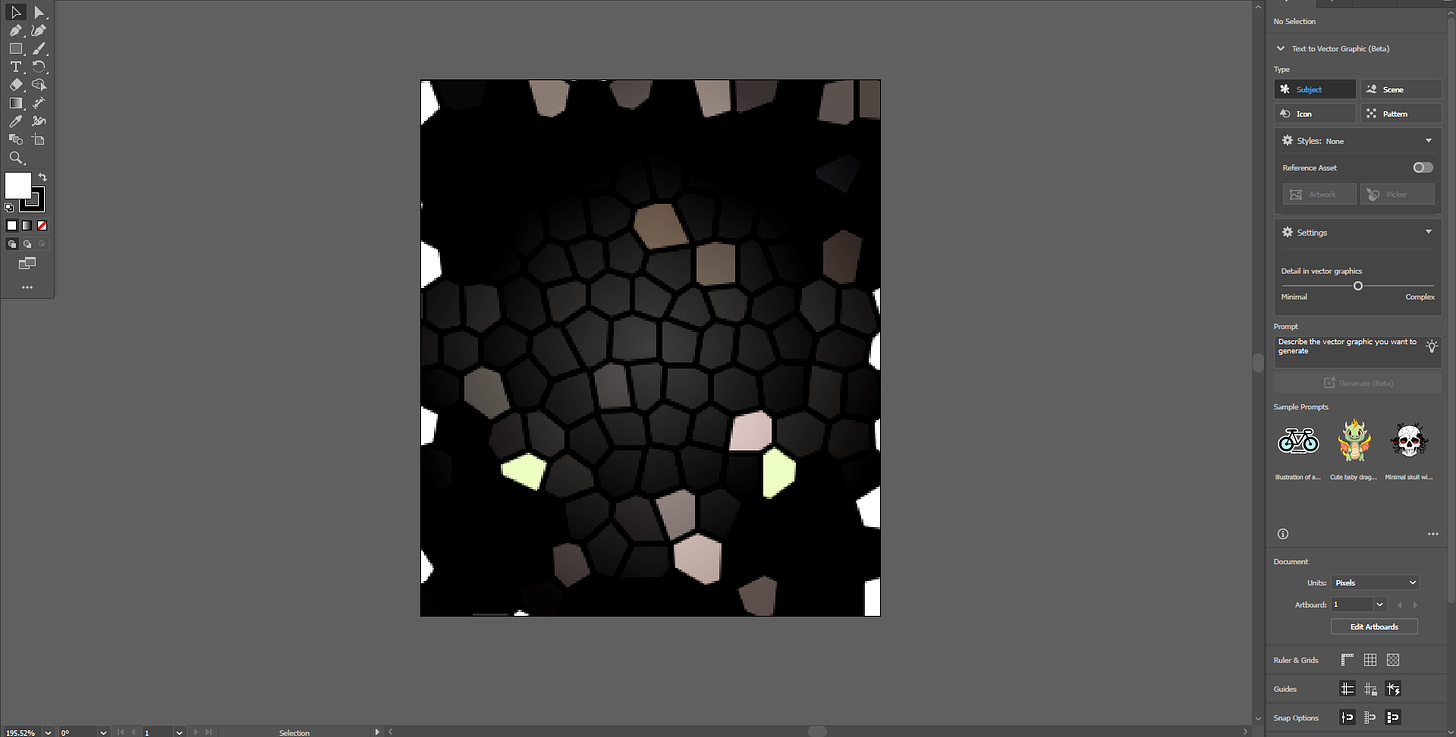
If you find an online image to use, you can copy it to the canvas. Otherwise, you can make your own. For this example, I just made some neat-looking stained glass frames.
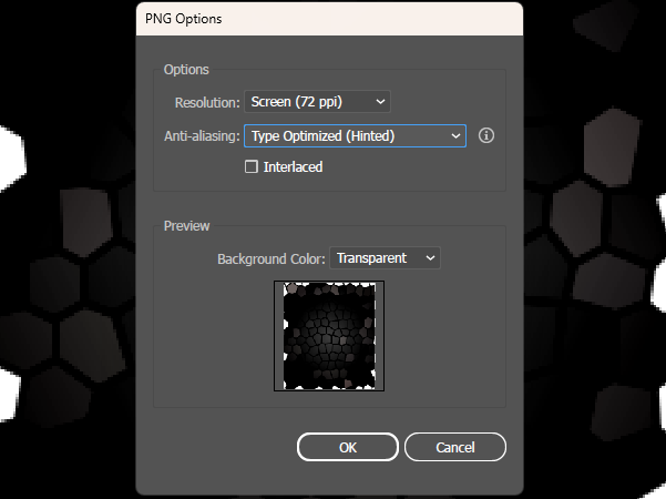
When you’re done with your design, export it as a PNG image.
*This image is downloadable.
With that, open up ESP-IDF and navigate to the main.c file.
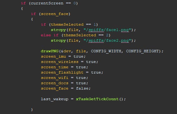
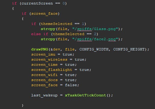
From there, scroll down to the ST7789 task. Within the task, only a bit below the start, you should see some code that looks like this:
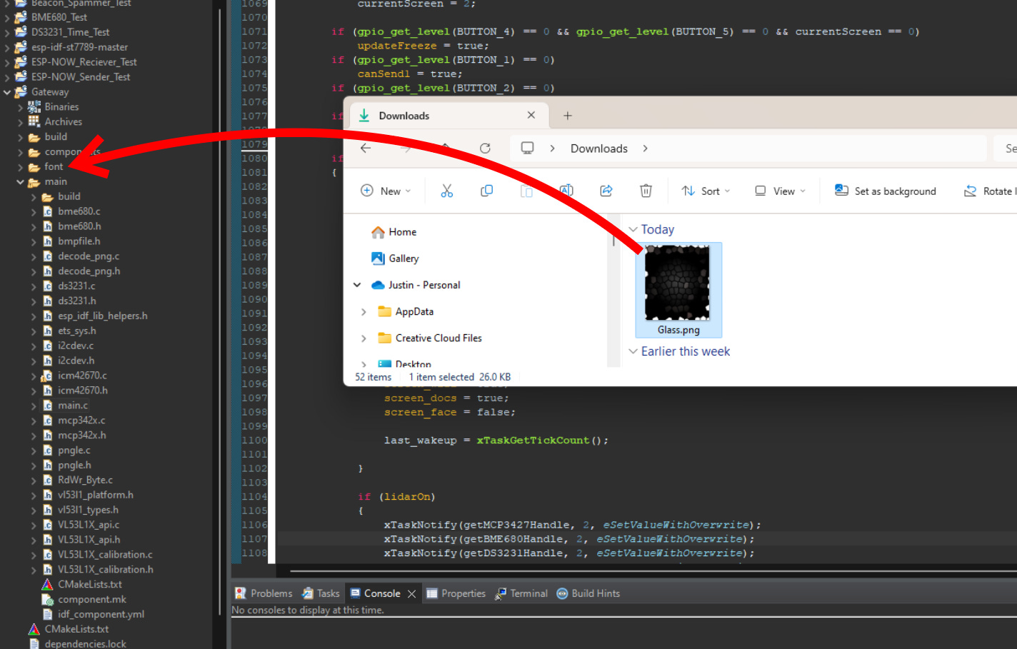
This is the code first executed when switching to the main watch face (screen 0). The two lines of code mentioning the face1 and face2 PNGs are the two default watch faces I made. Depending on your default theme (1 for steampunk, 2 for planets), this is the line of code that you'll change to update your watch face. All you have to do is drag the new image you created into the font file, click on “copy”, then change the text from face1 (or face2) to the name of the image. In my case (the default theme was steampunk), I’ll change it to “Glass”.
*This text is case-sensitive!
Then just like that, your watch face is updated to the image you made for it!
*Default text locations will be different depending on the theme selected. Above is the text for theme 1/steampunk
Note: You will have to repeat this process for the other screens (currentScreen = 1, 2, etc.) if you want to change those as well. It may also be necessary to adjust the coordinates (xpos and ypos variables) if you want to change where any text is located. This should all be done within the ST7789 function.
BOM
This is the Bill of Materials for my Gateway Smartwatch project!
I’ll put everything that you need to have here so that you don’t have to go scrolling around looking for the links I sprinkled throughout the article.
- All the CAD for this project can be found on my Thingiverse. Everything else including the Gerber files, part list, etc. can be found here on my GitHub.
- The editable STEP files, logo-less STL files, door locker CAD, light switcher CAD, and editable PCB files are available here to paid subscribers. Thanks so much for your support!
- LCD screen
- Laser module
- 400mAh Lithium-ion Polymer battery
- Magnetic Apple watch band (if not, these generic ones are also fine)
- Magnetic charger (optional)
- Glass screen protector
- Optional (if you don’t already have them):
- Mini soldering iron (what I use, but any will do)
- Solder paste
- Solder (my roll of choice)
- Hot plate
- Hot air rework gun (great for fixing broken or misaligned ICs)!
- Some nuts & bolts
- Basic screwdriver kit (one of many options)
Disclosure: These are affiliate links. I get a portion of product sales at no extra cost to you.
Thanks so much for reading! I hope this was a helpful and informative article. If you decide to do the build, please feel free to leave any questions in the comments below. If not, I hope you were still able to enjoy reading and learn something new!
Have constructive criticism or a suggestion for a future project? I’m always looking to improve my work. Leave it in the comments! Until next time.
Be sure to follow me on Instagram! :)
If you feel this read was worth at least $5, please consider becoming a paid subscriber. I don’t use ads, so I rely on your support to keep going! You will also receive the following benefits.
