ESP Something
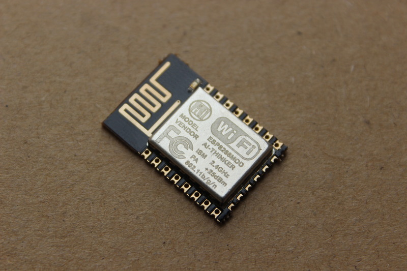
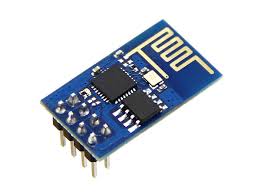
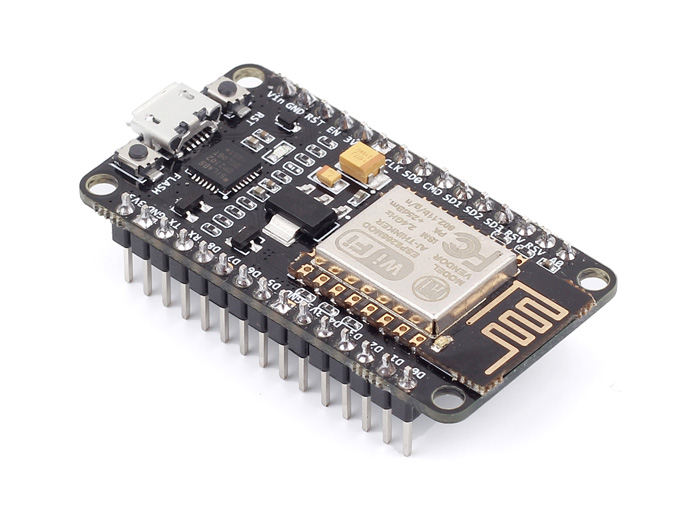
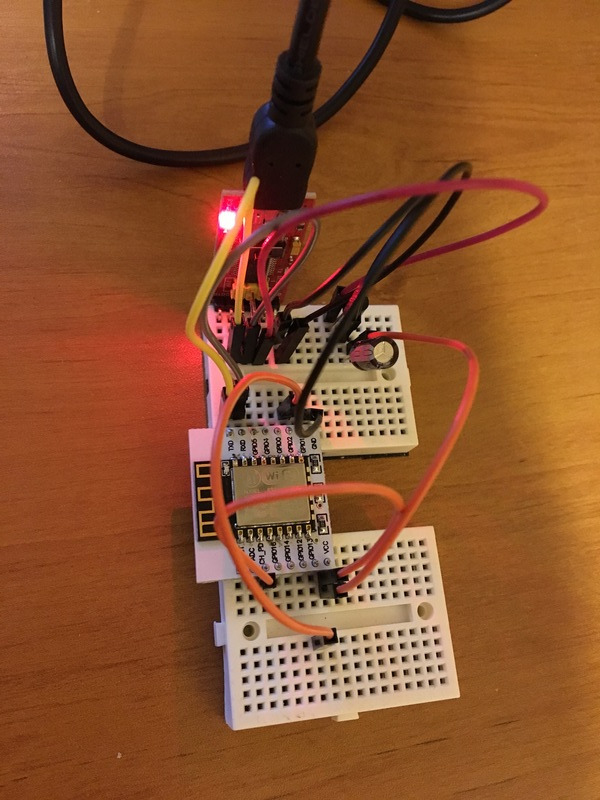
My purpose here is to share my experience with the ESP8266 through the ESP-01, ESP-12 and NodeMCU modules.
I'll explain :
1. How to connect ESP-01 to your computer
2. Reload the AT firmware
3. Use Arduino IDE to program the chip
4. Node MCU experience
5. DeepSleep or power your module with battery
6. Pure ESP12 - Connect it to your computer and get ready for embedded projects
ESP-01 - Communication Test
You need :
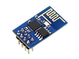
- ESP-01 module of course
- Serial-USB adapter
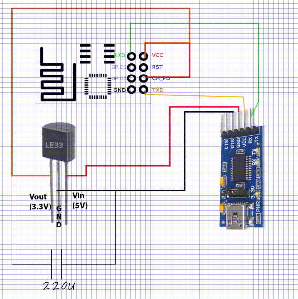
- A 3.3V regulator, I used a LE33CZ (max 100mA), it works but I recommend a model with 1A Max.
Follow the schematic.
Note: CH_PD needs to be connected to +VCC, as it is mentioned in the datasheet of ESP8266.
Communicate with the ESP :
Normally when you buy such module :
- the AT firmware is already in the memory
- the default serial speed is 115200 bps
Theoretically you may use any Serial Communication software. Just take care to add New Line & Carriage Return after each command.
- I tried to use PutTTY to send AT commands but with no success, because of these New Line & Carriage Return characters. I didn't find the way to do it.
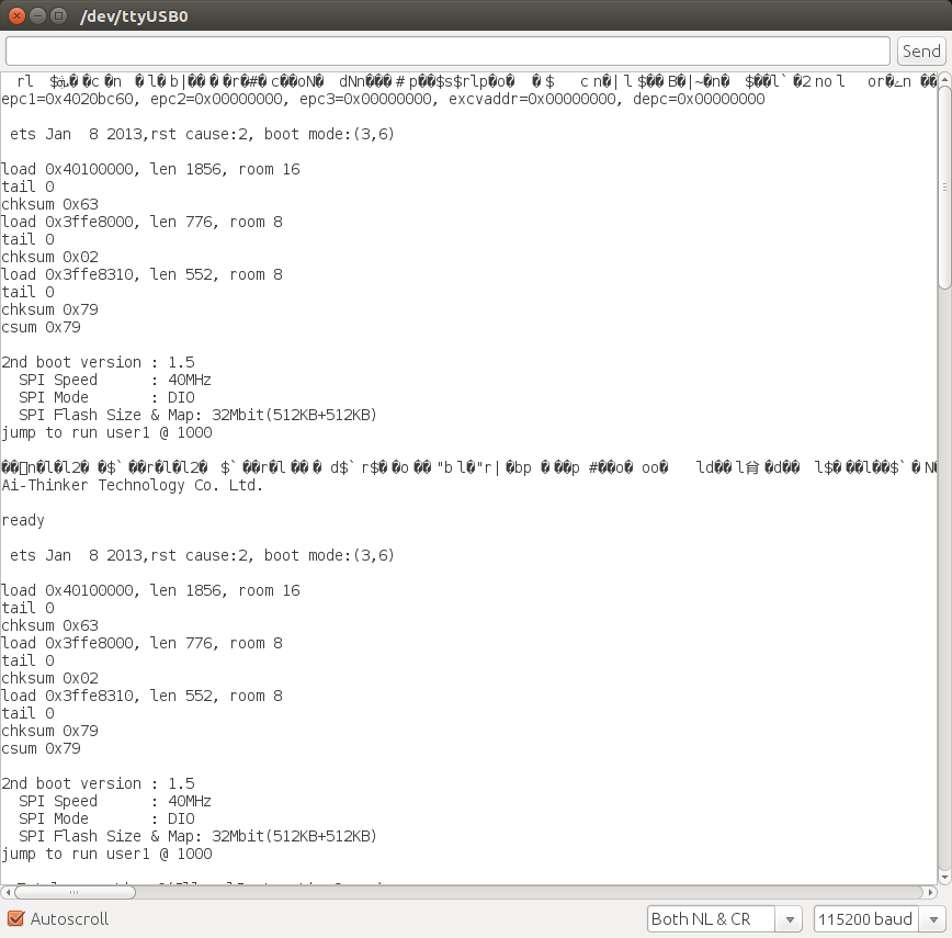
- So I used the serial monitor of ARDUINO, take care to set up "Both NL&CR" else it won't work.
Once you're ready :
- Try to type : AT
- ESP should answer : OK
Now you're in. Refer to Espressif documentation for AT commands.
With AT commands you can connect to WiFi and create an HTTP server. But you cannot command GPIO.
Downloads
ESP-01 - Reload the AT Firmware
In case when you receive the module there is no software inside (but normally it is), I explain here how to reload it with a multi-platform tool.
You can skip this step if the previous one was ok for you.
First thing you need to know :
- To enter in program mode you need to put GPIO0 at 0V and do a RESET while GPIO0 is still at 0V.
- Then the module is ready to load firmware in the flash memory
Go to Espressif.com to download the SDK :
- In the folder bin/at, the README file will tell you what files to load in the memory and the start addresses
Example :
# NON-BOOT MODE
## download
eagle.flash.bin 0x00000
eagle.irom0text.bin 0x10000
blank.bin
Flash size 8Mbit: 0x7e000 & 0xfe000
Flash size 16Mbit: 0x7e000 & 0x1fe000
Flash size 16Mbit-C1: 0xfe000 & 0x1fe000
Flash size 32Mbit: 0x7e000 & 0x3fe000
Flash size 32Mbit-C1: 0xfe000 & 0x3fe000
esp_init_data_default.bin (optional)
Flash size 8Mbit: 0xfc000
Flash size 16Mbit: 0x1fc000
Flash size 16Mbit-C1: 0x1fc000
Flash size 32Mbit: 0x3fc000
Flash size 32Mbit-C1: 0x3fc000
Note : You need to know the size & type of memory you have in your module. That's a point we will deal with in few seconds...
Use esptool.py to load the firmware :
- Espressif recommends to use their own software, but it is on Windows
- So https://github.com/espressif/esptool is a good alternative
- python esptool.py --port /dev/ttyUSB0 --baud 115200 write_flash 0x00000 ./at/noboot/eagle.flash.bin
- python esptool.py --port /dev/ttyUSB0 --baud 115200 write_flash 0x10000 ./at/noboot/eagle.irom0text.bin
- python esptool.py --port /dev/ttyUSB0 --baud 115200 write_flash 0x7e000 ./bin/blank.bin
- python esptool.py --port /dev/ttyUSB0 --baud 115200 write_flash 0xfc000 ./bin/esp_init_data_default.bin
- ...
Important note :
You cannot do these things if you do not know what kind of memory you have in your module.
I give you a tip :
python esptool.py --port /dev/ttyUSB0 --baud 115200 flash_id
Then check out the combo at https://code.coreboot.org/p/flashrom/source/tree/HEAD/trunk/flashchips.h:
manufacturer c8 is GigaDevice and device 4013 is GD25Q40, which is a 4Mbit=512KByte device
manufacturer ef is Winbond (ex Nexcom) and device 4016 is W25Q32, which is a 32Mbit=4MByte device
Use ARDUINO IDE
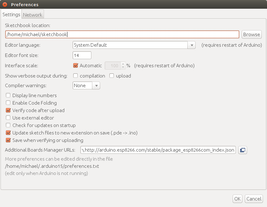
In the preferences settings, add this URL to "Additional Boards Manager URLs" :
http://arduino.esp8266.com/stable/package_esp8266c...
Restart ARDUINO after that. Then in "TOOL->BOARD" you will be able to select Generic ESP8266 Module.
In File->Examples you will find examples of sketches to help to start programming with ARDUINO.
Notes :
- When you download your program don't forget to enter in programming mode (GPIO0=0V and RESET).
- Once you have downloaded an arduino program on the ESP, the AT firmware is not available anymore, so AT commands are not to.
- Use the option : sketch + wifi settings
Node MCU
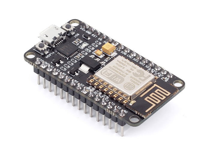
If you buy this kind of module, it is really convenient :
- ESP-12 inside
- You have a flash + reset button to enter easily in programming mode
- Pins
- An integrated USB port...
But if you want to integrate it in a project, it may not be the best. We will see the "pure" ESP12 at the end of this instructable.
DeepSleep or Power Your Module With Battery
It is cool to have WiFi but it takes power. If you let the module ON not sure you can embed it for a long time in a batteries project.
Fortunately the ESP can enter in deep sleep mode. It then consumes few micro-amps.
It is possible to do that with AT commands.
But I will show it through arduino programming.
First, wire WakeUpPin=GPIO16 to the RESET of the ESP. Because when the ESP enter in deep sleep mode, it wakes up by reseting itself through the GPIO16 pin.
To enter in DeepSleep mode, use the code : ESP.deepSleep(<time>,WAKE_RF_DEFAULT);
<time> is in micro-seconds. The ESP will sleep during <time> uS before reseting.
Pure ESP12 - Connect It to Your Computer and Get Ready for Embedded Projects
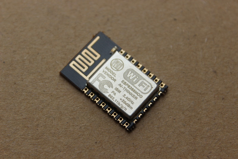
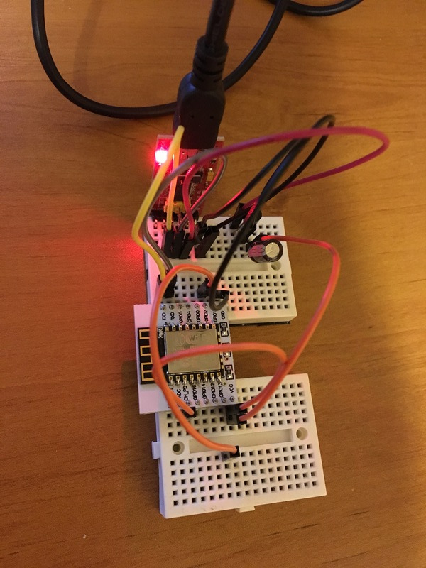
Don't be afraid to buy the pure ESP12 module. It is cheap, light and tiny.
Connect it the same way as the ESP-01 module, with a Serial-USB adapter.
Don't forget that CH_PD should be at Vcc.
Then you can make embedded projects, on batteries, with WiFi and a powerful micro-controller !!