ESP RainMaker IoT Project With Google Alexa Bluetooth IR Using ESP32 Control Relays
by techstudycell in Circuits > Microcontrollers
4958 Views, 22 Favorites, 0 Comments
ESP RainMaker IoT Project With Google Alexa Bluetooth IR Using ESP32 Control Relays
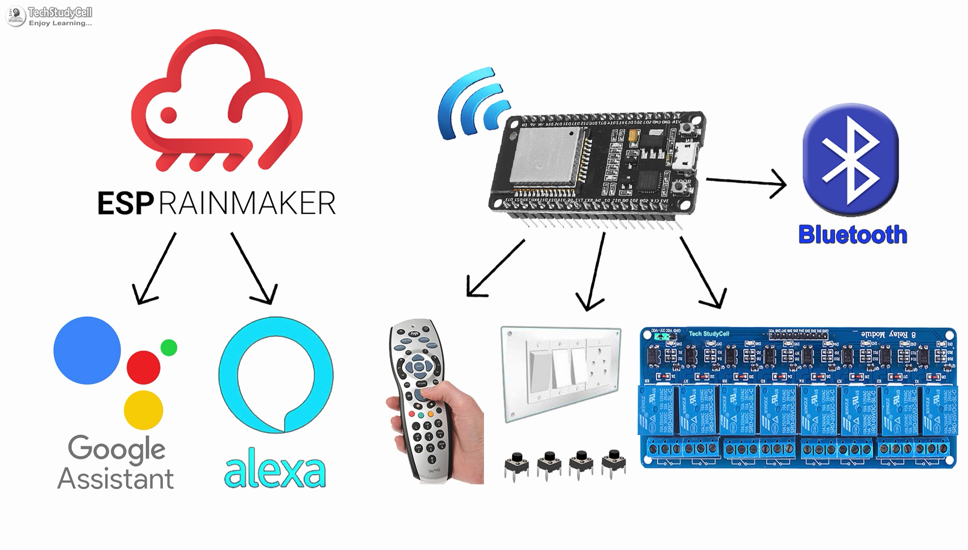
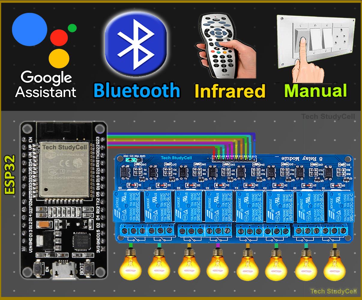
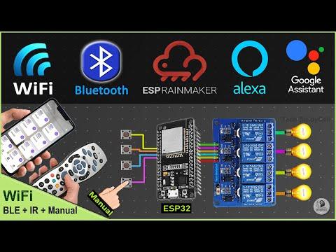
In this IoT project, I have shown how to make ESP RainMaker IoT Project using ESP32 to control relays with Google Assistant, Alexa, Bluetooth, IR remote, and manual switches. real-time feedback.
I have shown all the steps to make this ESP32 home automation system in the article.
This ESP32 control smart relay has the following features:
- Control home appliances with WiFi (Google Home & Amazon Alexa app).
- Control home appliances with Voice Commands using Google Assistant & Alexa.
- Control home appliances with any Bluetooth or BLE module.
- Control home appliances with an IR remote.
- Control home appliances with manual switches or push buttons.
- Monitor real-time feedback in the ESP RainMaker App.
- Control appliances without WiFi (Bluetooth + IR Remote + Switches).
So, you can easily make this home automation project at home just by using an ESP32 and relay module. Or you can also use a custom-designed PCB for this project.
Supplies
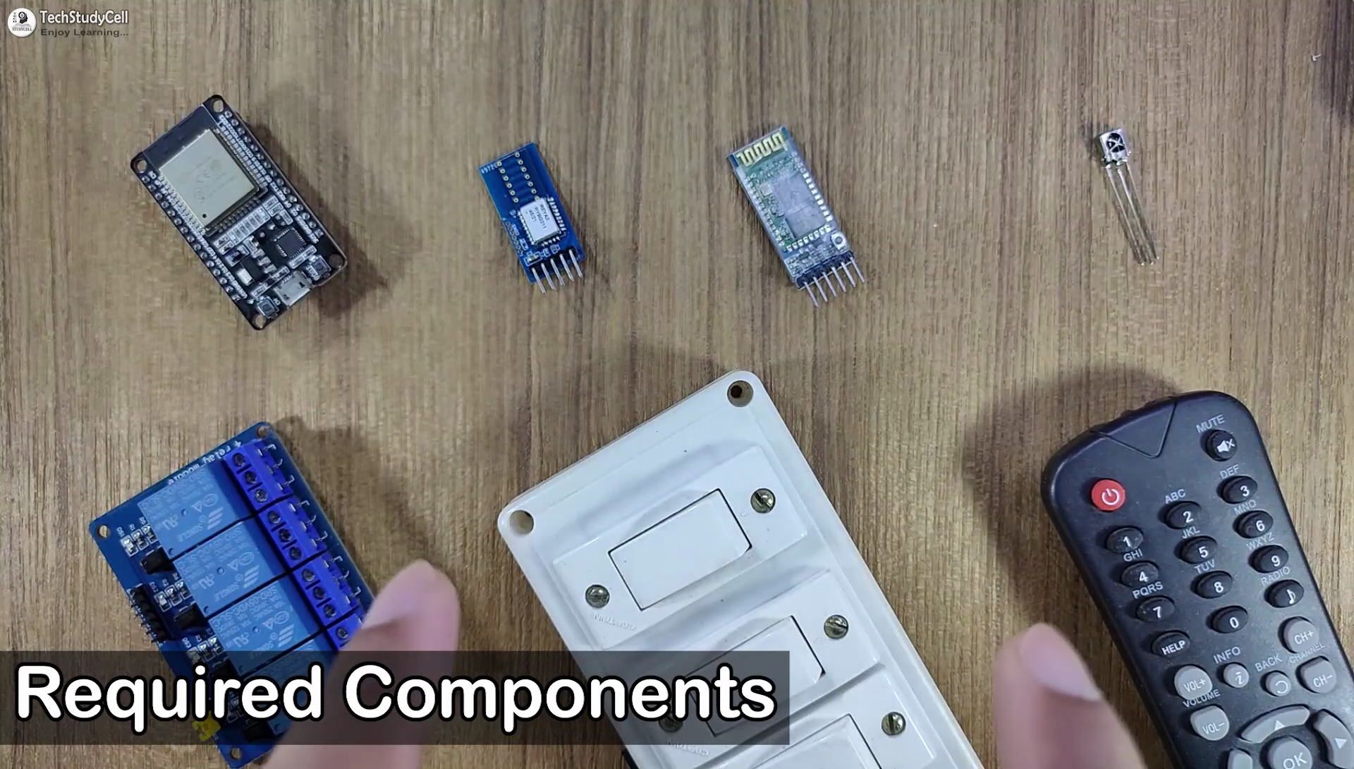

Required components:
- ESP32 DevKIT V1 Amazon
- 4-channel or 8-channel 5V SPDT Relay Module Amazon
- TSOP1838 IR receiver (with metallic casing)
- Bluetooth or BLE module (ANY)
- Manual Switches or Pushbuttons Amazon
- Any IR Remote
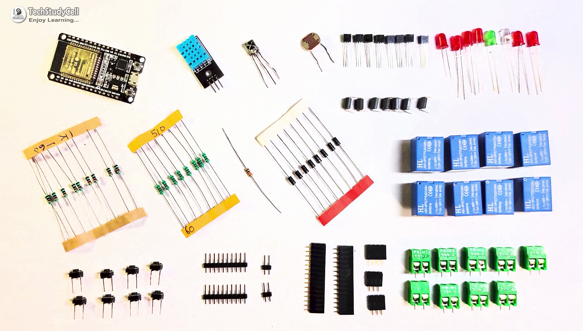
Required components for PCB:
- ESP32 DEVKIT V1
- TSOP1838 IR receiver (with metallic case)
- Relays 5v (SPDT) (8 no)
- BC547 Transistors (8 no)
- PC817 Optocuplors (8 no)
- 510-ohm 0.25-watt Resistor (8 no) (R1 - R8)
- 1k 0.25-watt Resistors (10 no) (R9 - R18)
- LED 5-mm (10 no)
- 1N4007 Diodes (8 no) (D1 - D8)
- Push Buttons (8 no) or Switches
- Terminal Connectors
- Jumper
- 5V DC supply
Circuit Diagram of the ESP32 IoT Project
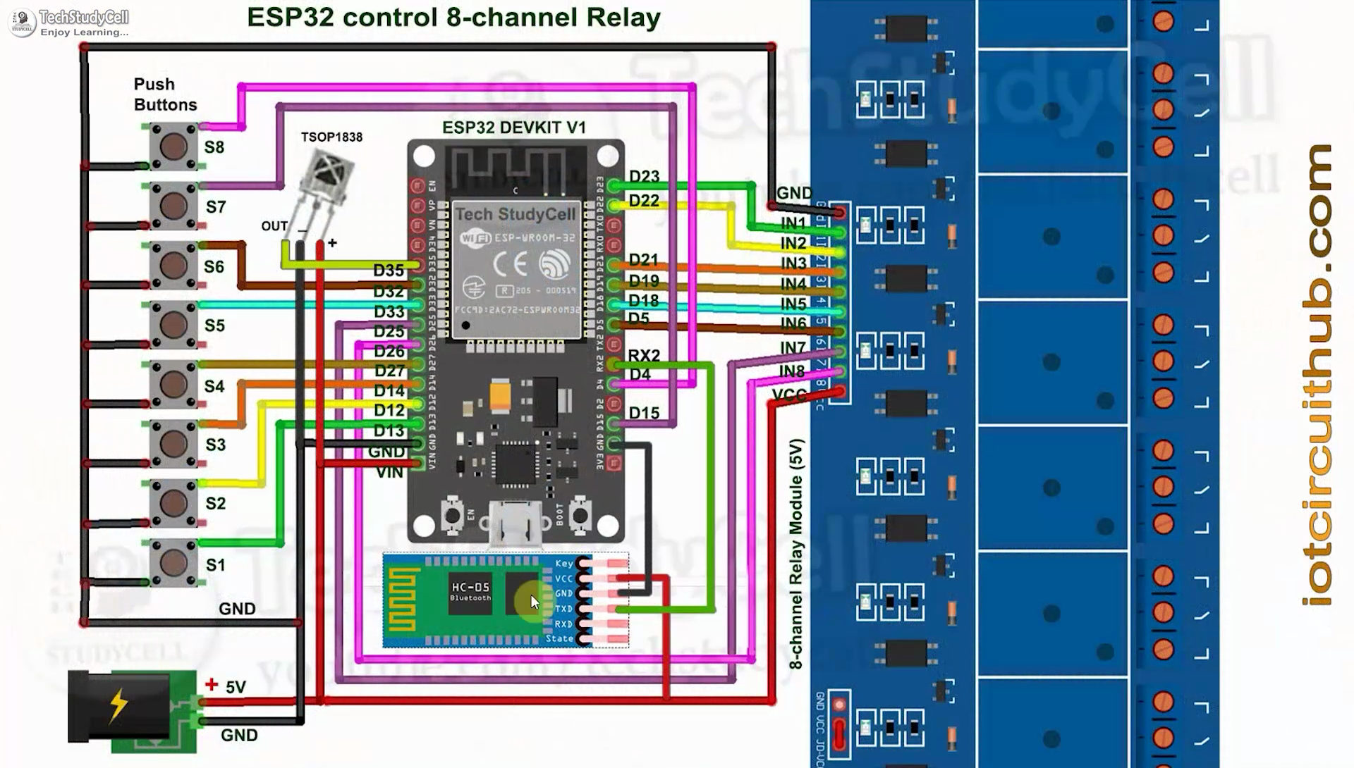
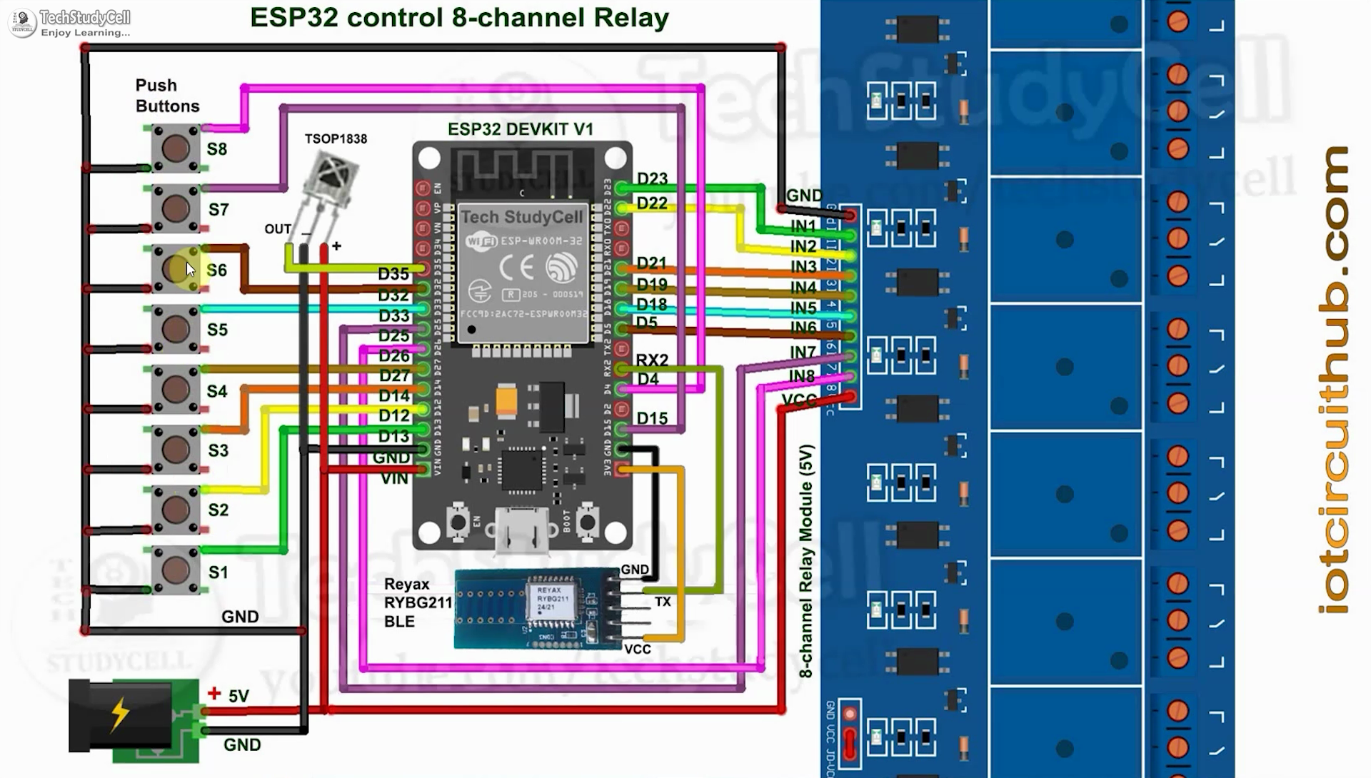
This is the complete circuit diagram for this home automation project. I have explained the circuit in the tutorial video.
The circuit is very simple, I have used the GPIO pins D23, D22, D21, D19, D18, D5, D25 & D26 to control the 8 relays.
And the GPIO pins D13, D12, D14, D27, D33, D32, D15 & D4 are connected with pushbuttons to control the 8 relays manually.
And the output pin of the IR Receiver is connected with GPIO D35.
For Bluetooth control, you can connect any Bluetooth or BLE modules with ESP32. In the first circuit, I have connected the HC-05 Bluetooth module with ESP32.
If you want to use any 3.3V BLE module, then refer to the second circuit.
The TX pin of the Bluetooth or BLE module is connected with the RX2 (GPIO16) pin of ESP32 for serial communication.
I have not used the inbuilt BLE of ESP32 as it is used to Reset WiFi details through OTA from the ESP RainMaker app.
I have used the INPUT_PULLUP function in Arduino IDE instead of using the pull-up resistors.
I have used a 5V 5A DC power supply.
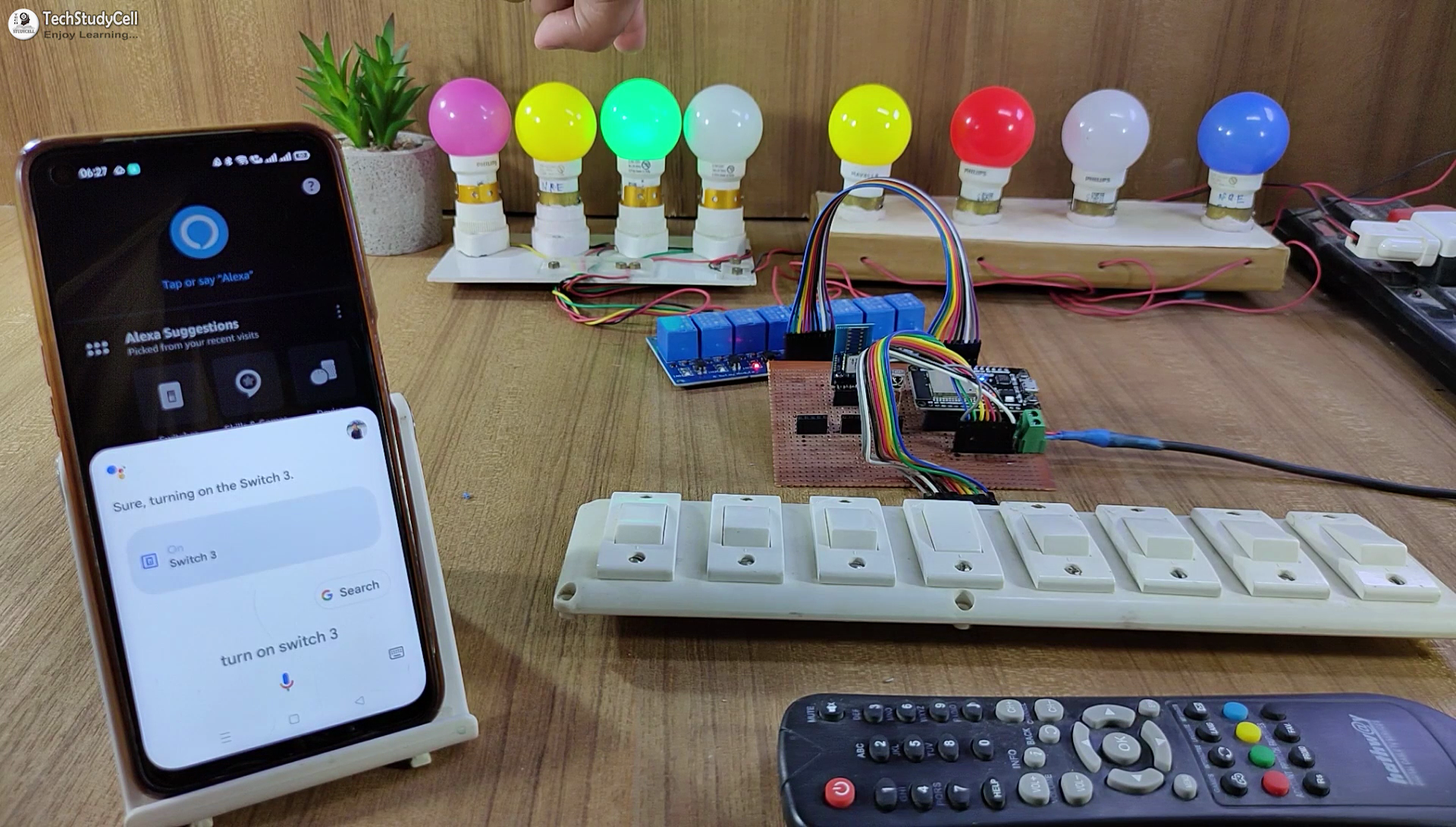
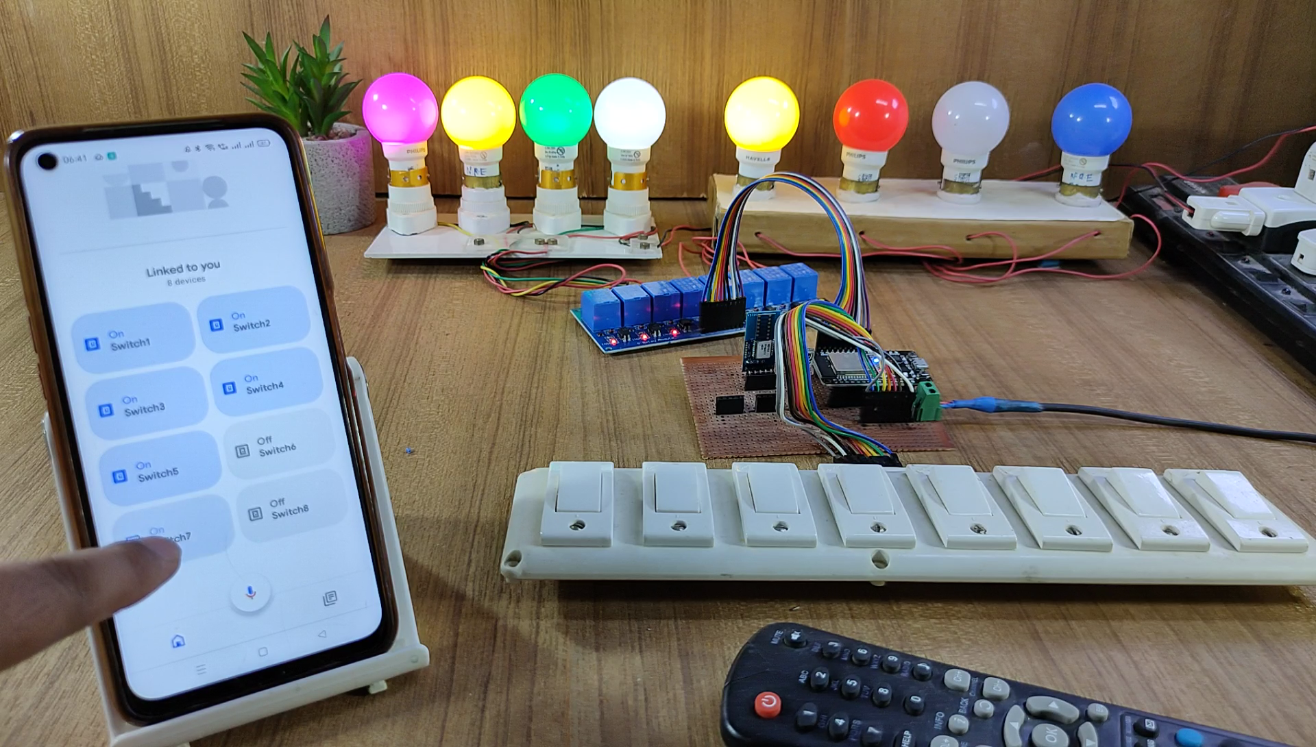
Google Assistant & Alexa Control Relay Using ESP32
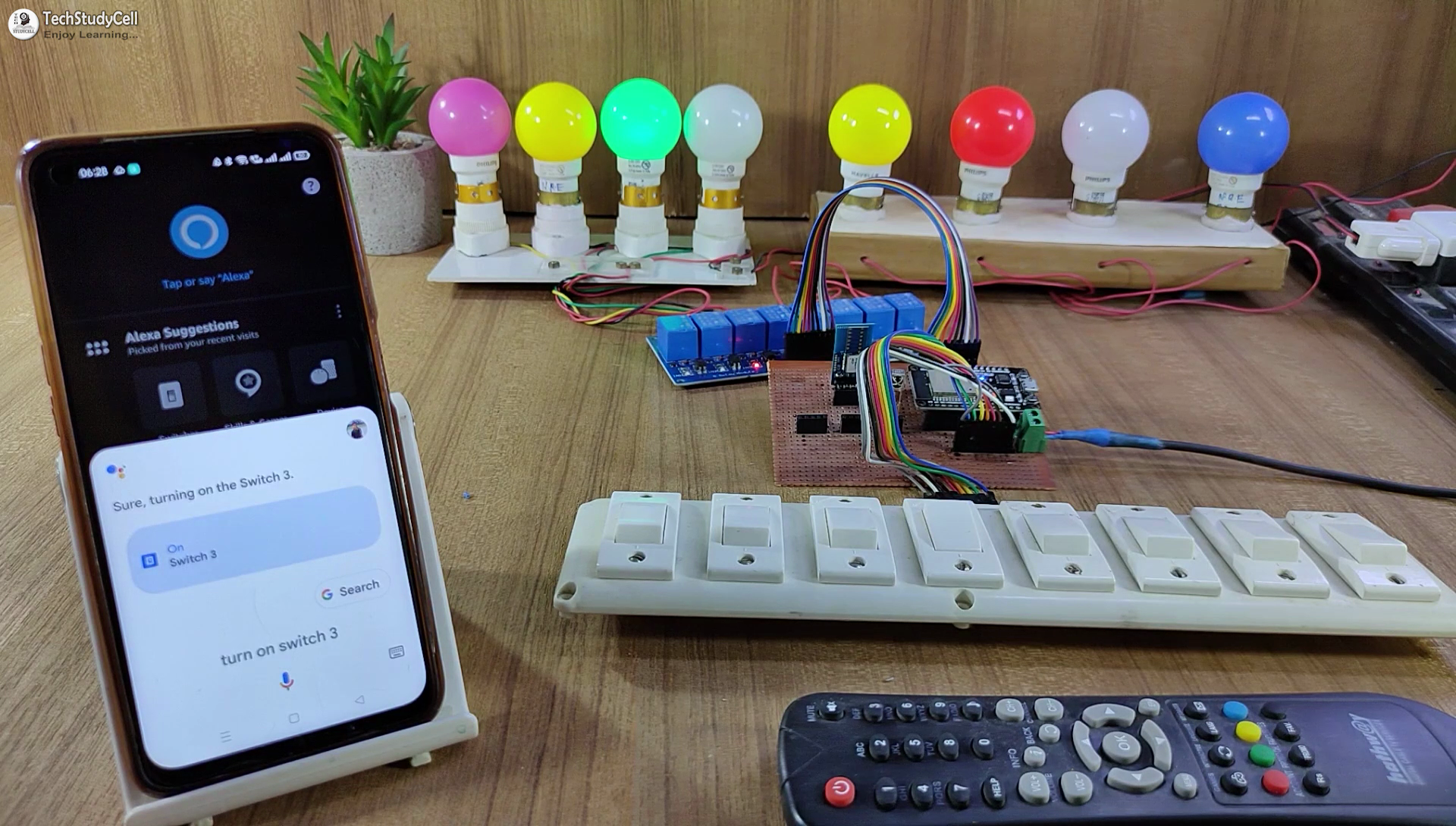
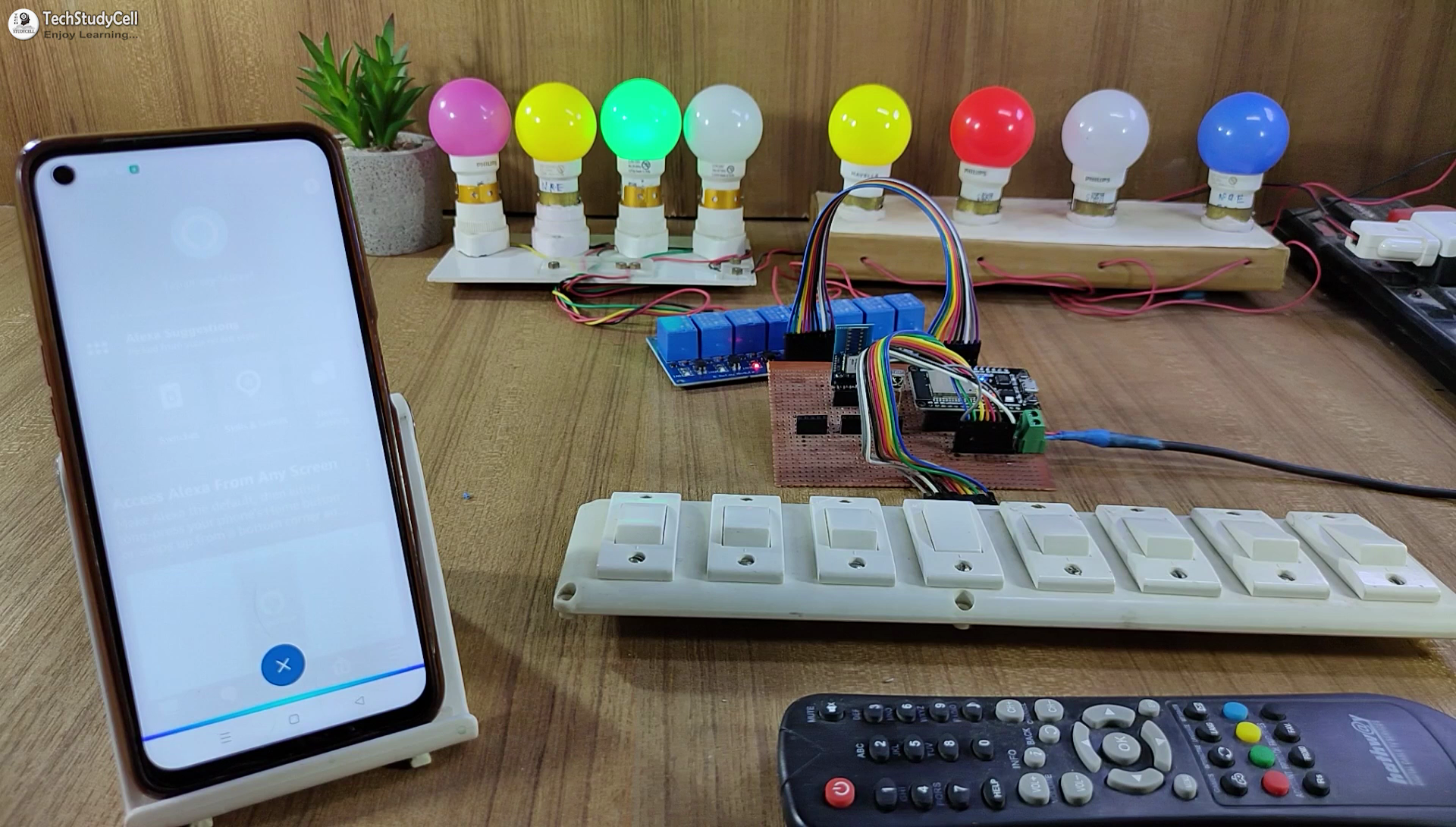
If the ESP32 is connected with WiFi, then you can control the home appliances with voice commands using Google Assistant and Amazon Alexa.
You can also control, and monitor the real-time feedback of the relays on the Google Home & Amazon Alexa App from anywhere in the world.
You don't need any ECHO device or Google Home Nest device for this home automation project.
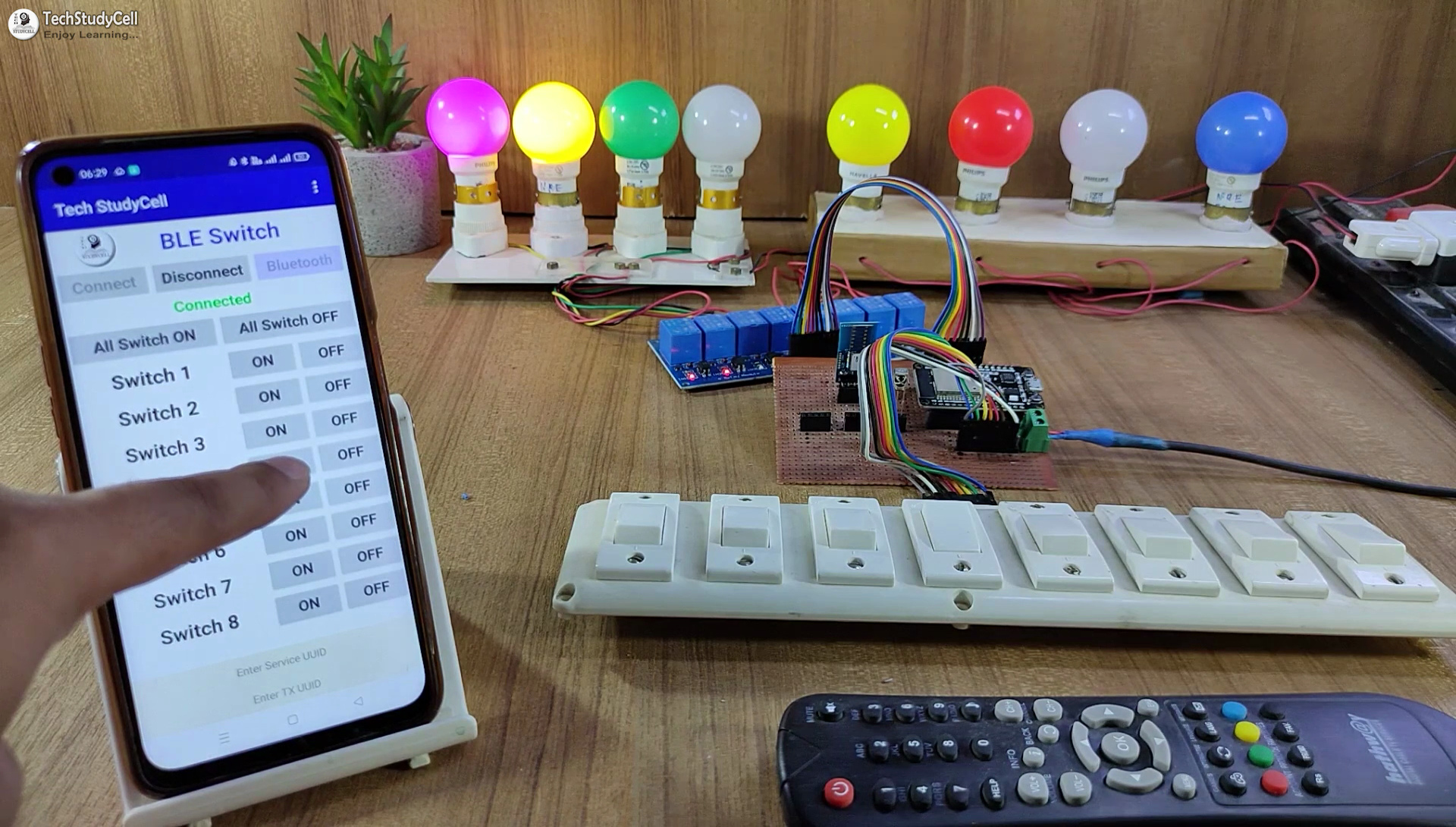
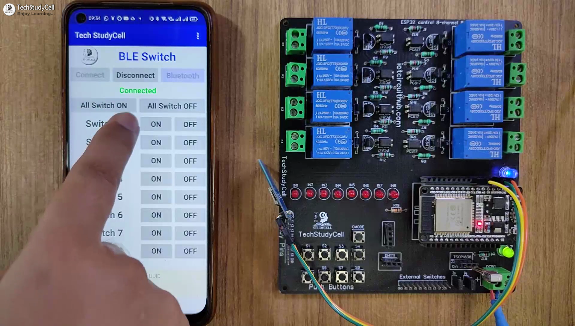
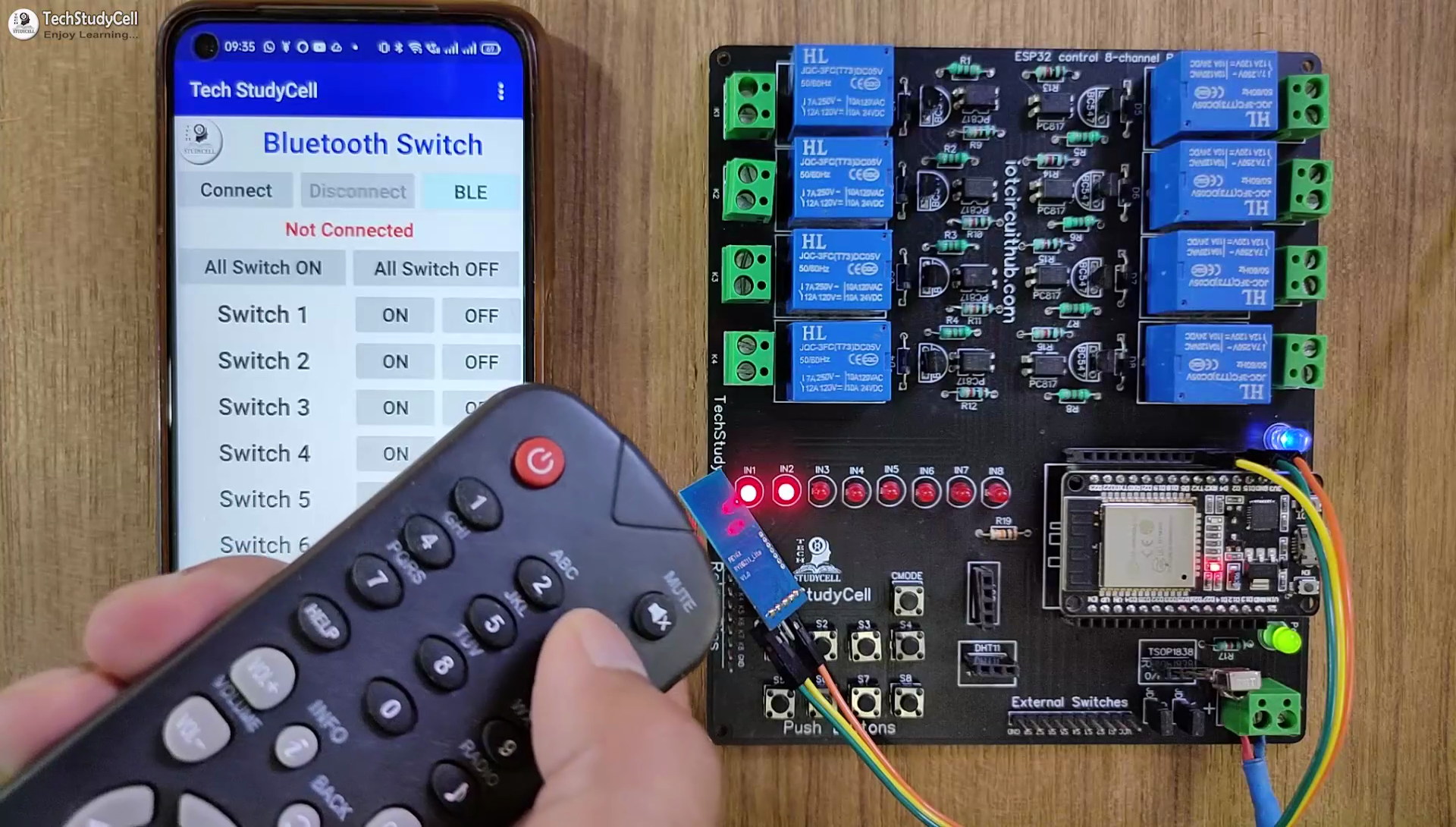
Control Relays With Bluetooth or BLE
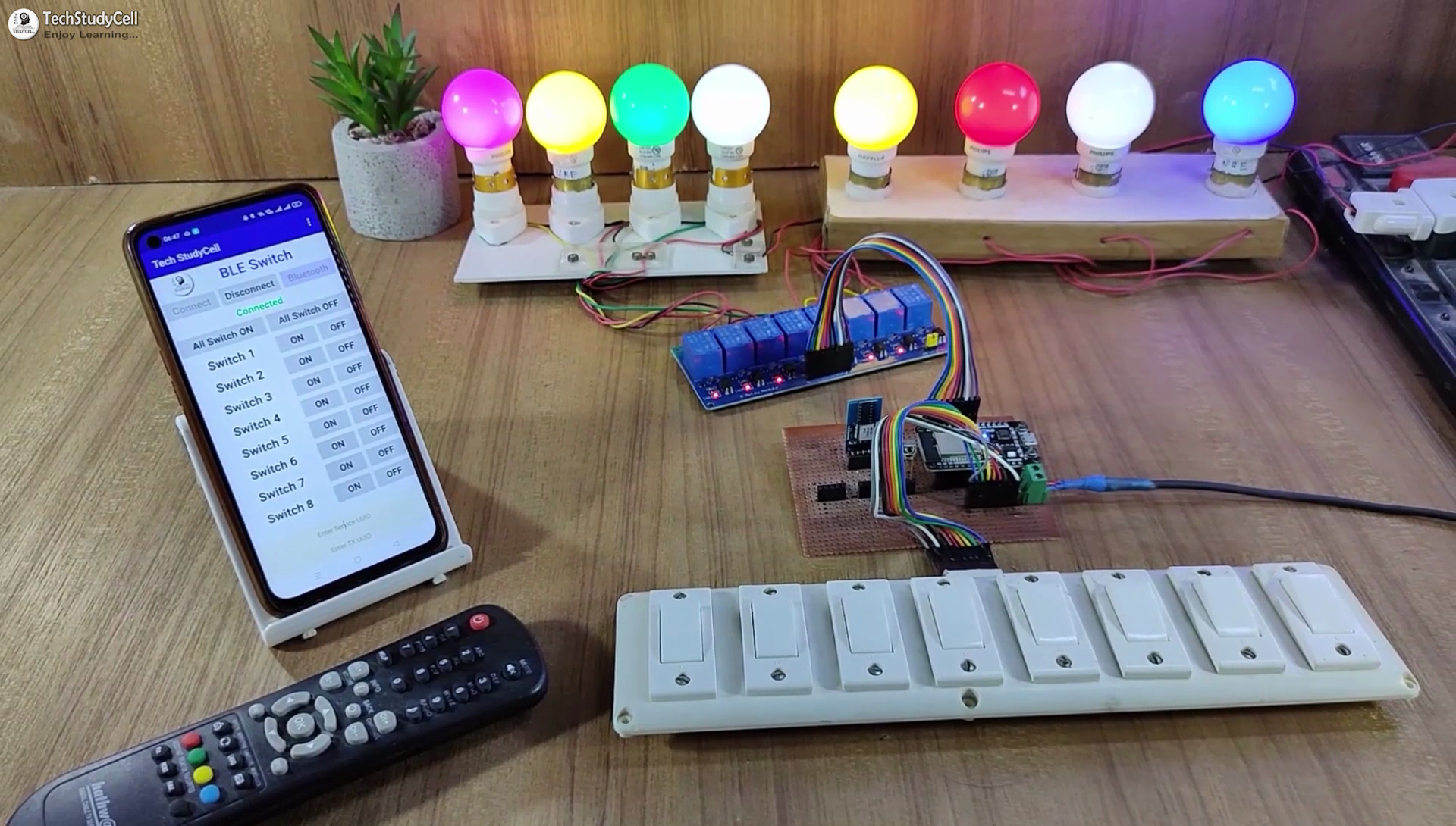
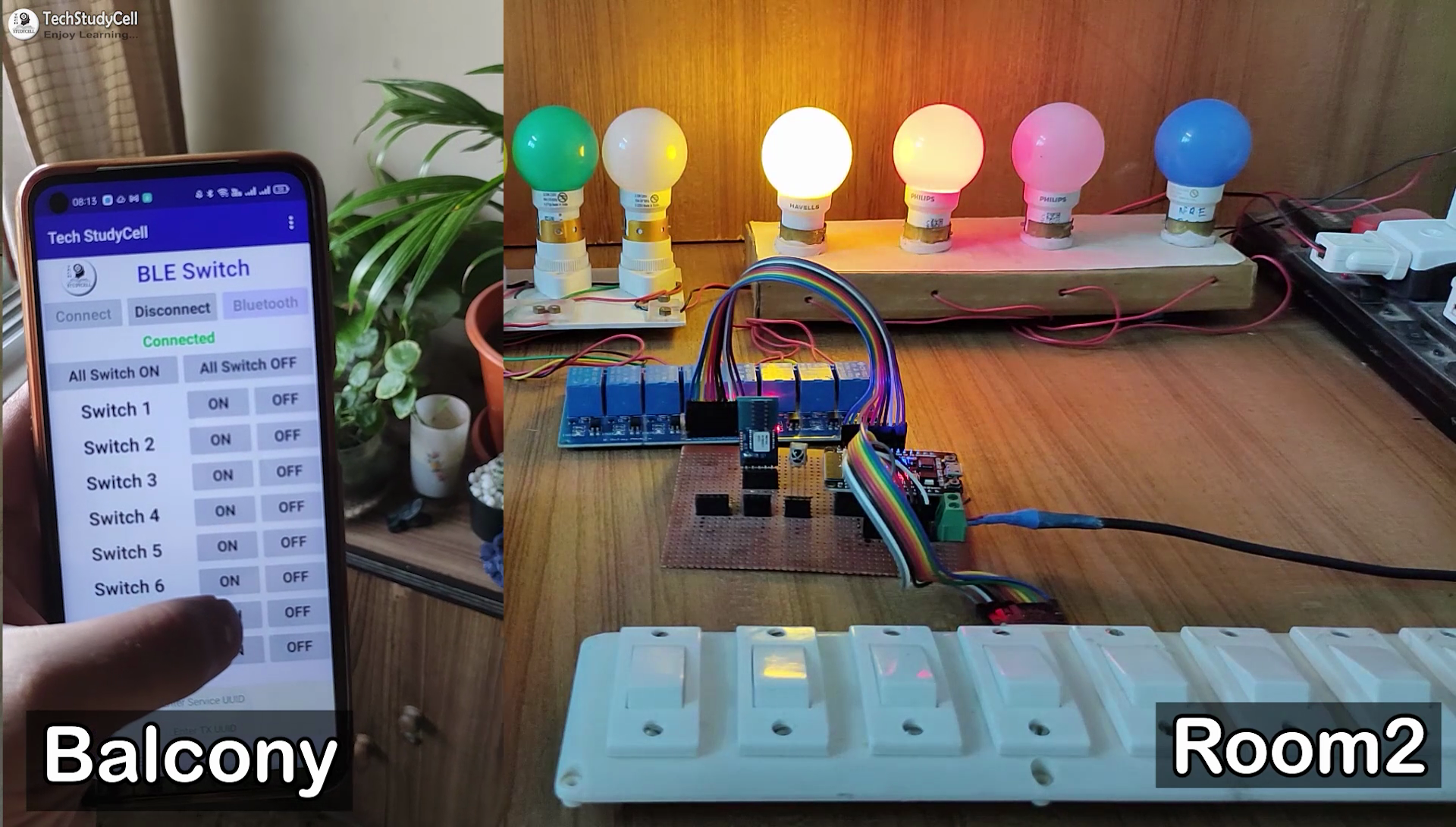
If the ESP32 is not connected with WiFi, still you can control the relays from mobile using Bluetooth.
You can use any Bluetooth or BLE module. It will send the signal to ESP32 through serial communication.
First, pair the Bluetooth module, then connect the module with the Bluetooth Switch app.
Download the Bluetooth App used for this ESP32 Project.
Downloads
IR Remote & Manual Switch Control Relay Using ESP32
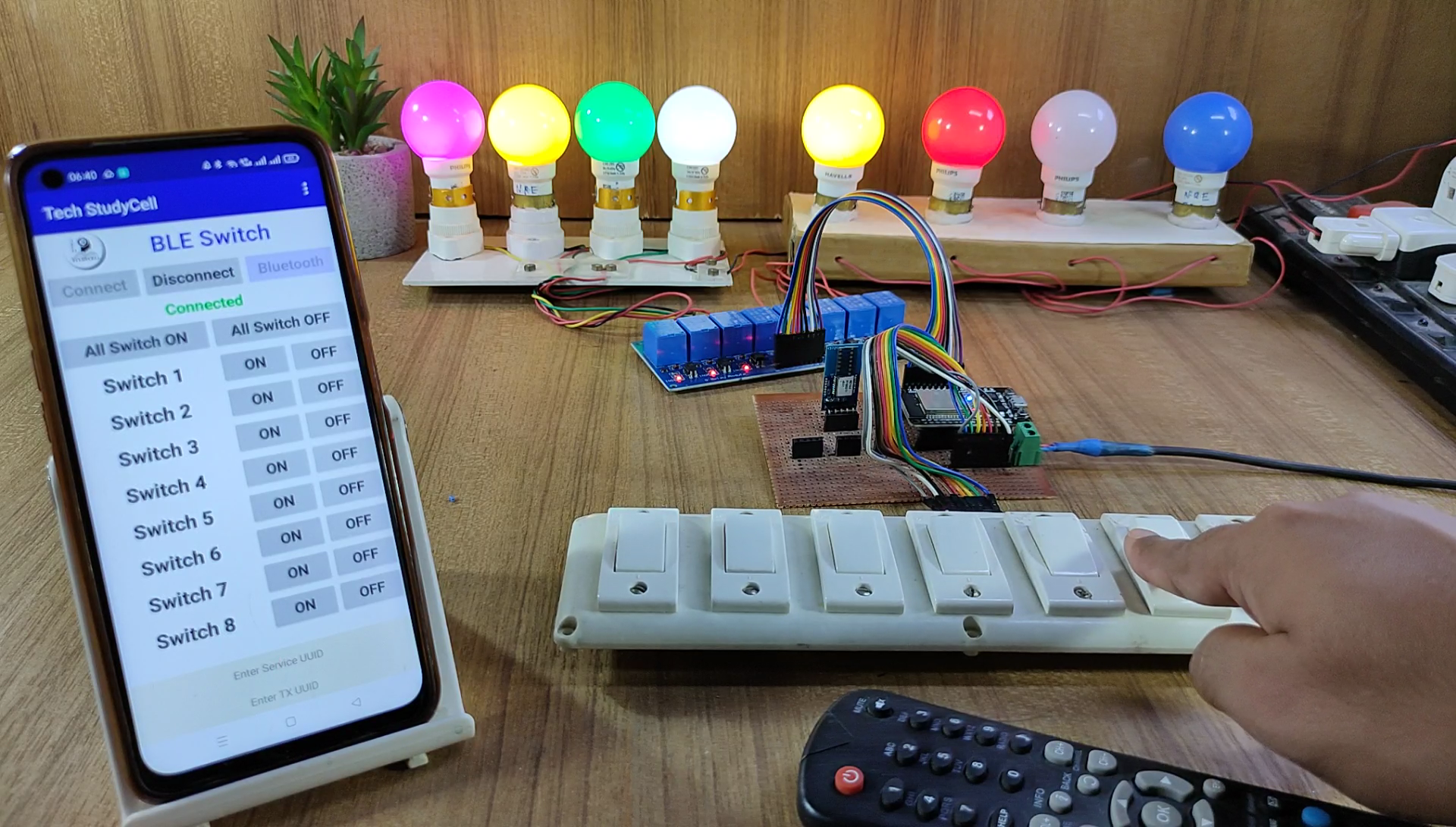
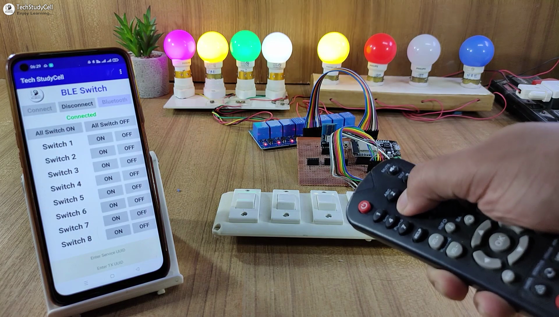
You can always control the relays from the IR remote or switches. For this project, you can use any IR remote.
You can monitor the real-time feedback in the ESP RainMaker App.
I have explained how to get the IR codes (HEX codes) from any remote in the following steps.
Please refer to the circuit diagram to connect the pushbuttons or switches.
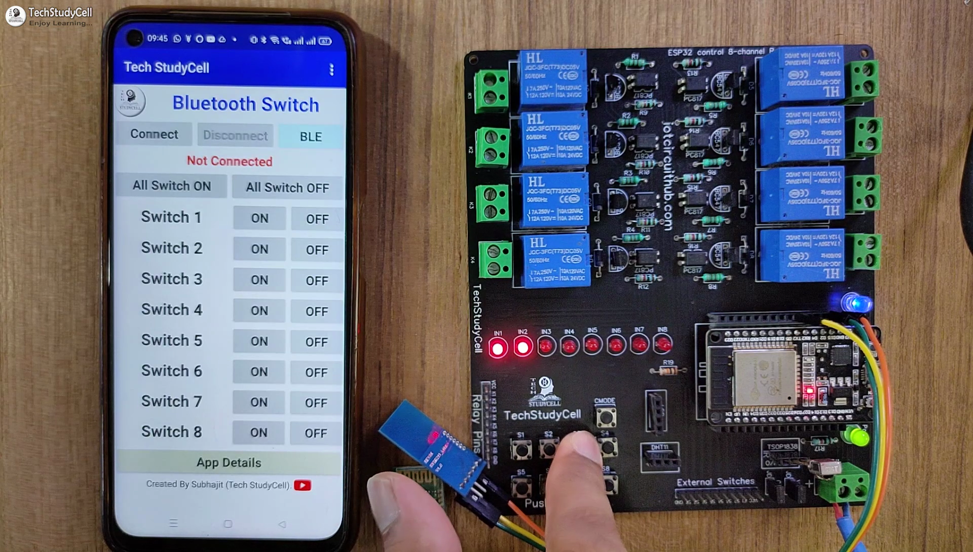
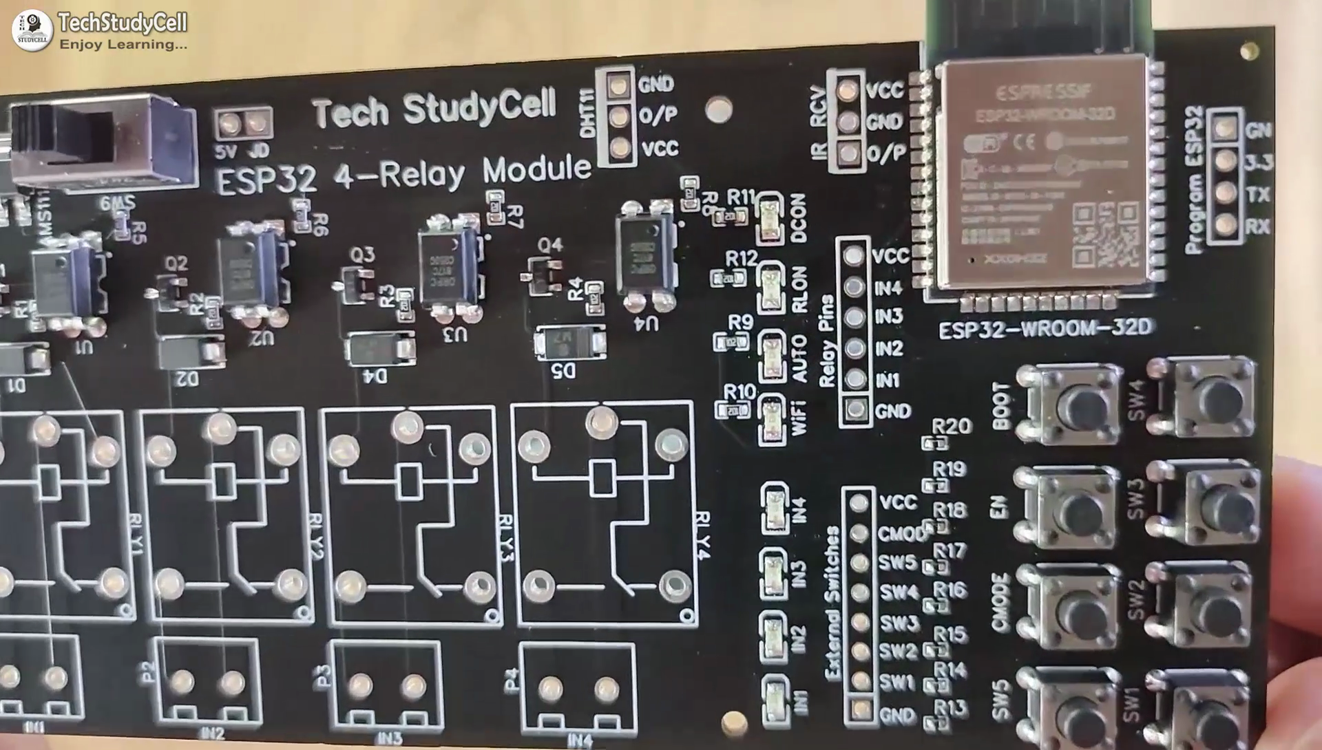
Design the PCB for This Smart Home System
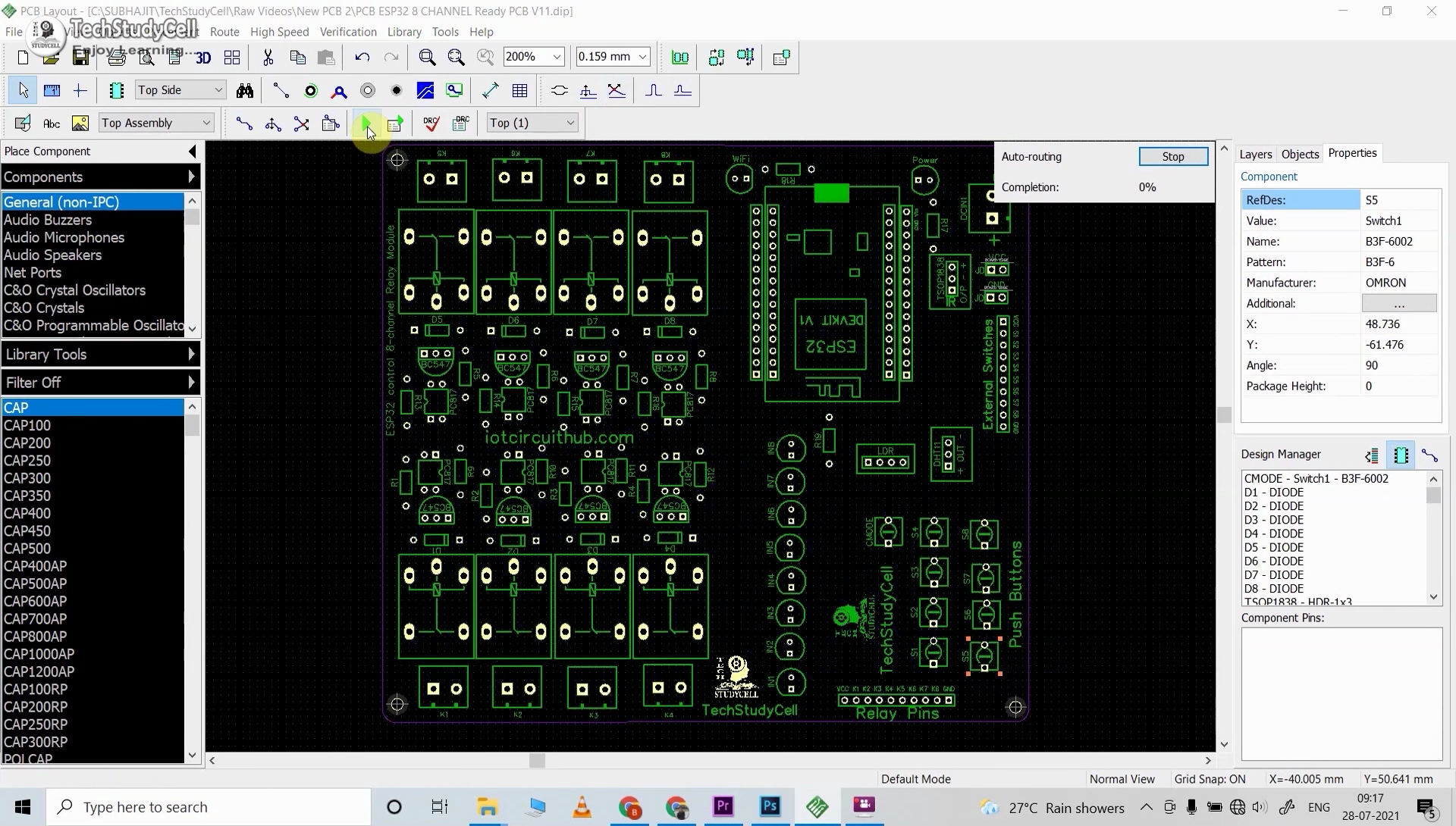
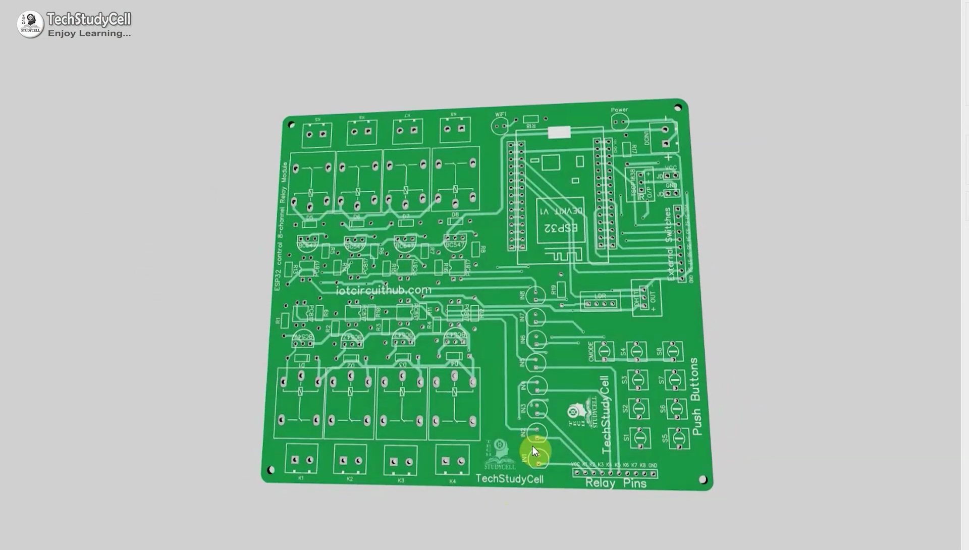
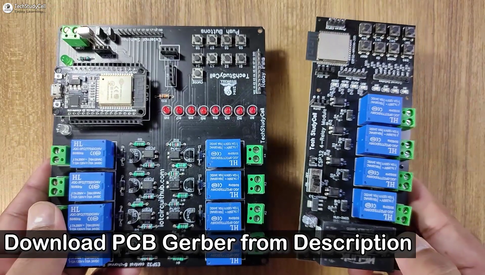
To make the circuit compact and give a professional look, I designed the PCB after testing all the features of the smart relay module.
You can download the PCB Gerber files of this ESP32 control relay PCB from the following link:
Why You Should Use JLC SMT Service?
On JLCPCB's one-stop online platform, customers enjoy low-cost & high-quality & fast SMT service at an $8.00 setup fee($0.0017 per joint).
$27 New User coupon & $24 SMT coupons every month.
Visit https://jlcpcb.com
JLCPCB SMT Parts Library 200k+ in-stock components (689 Basic components and 200k+ Extended components)
Parts Pre-Order service https://support.jlcpcb.com/article/164-what-is-jlcpcb-parts-pre-order-service
Build a Personal library Inventory, save parts for now or the future
Assembly will support 10M+ parts from Digikey, mouser.
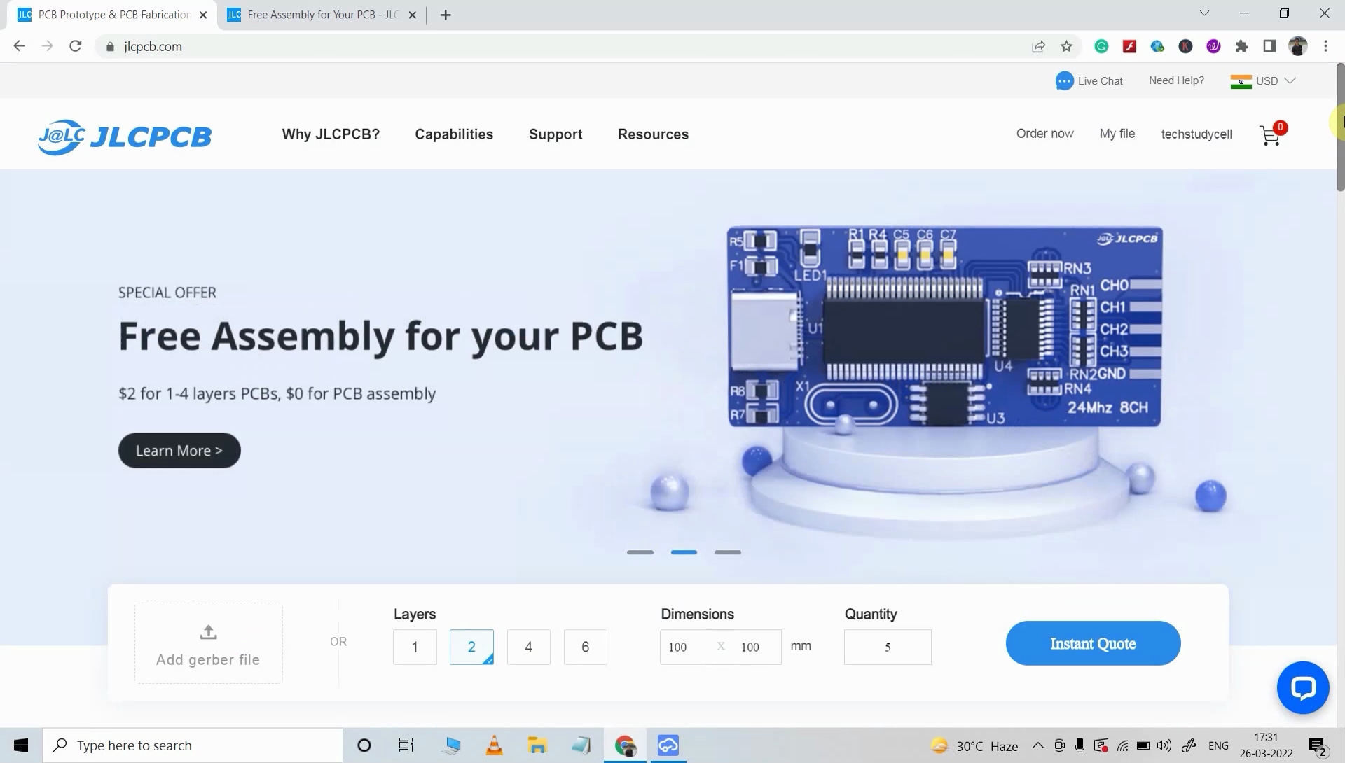
Steps to Order the PCB Assembly From JLCPCB
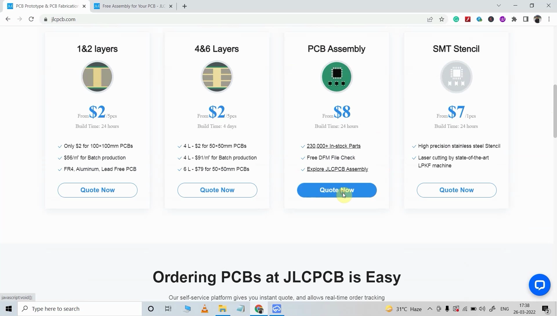
- Visit https://jlcpcb.com/ and Sign in / Sign up.
- Click on the QUOTE NOW button.
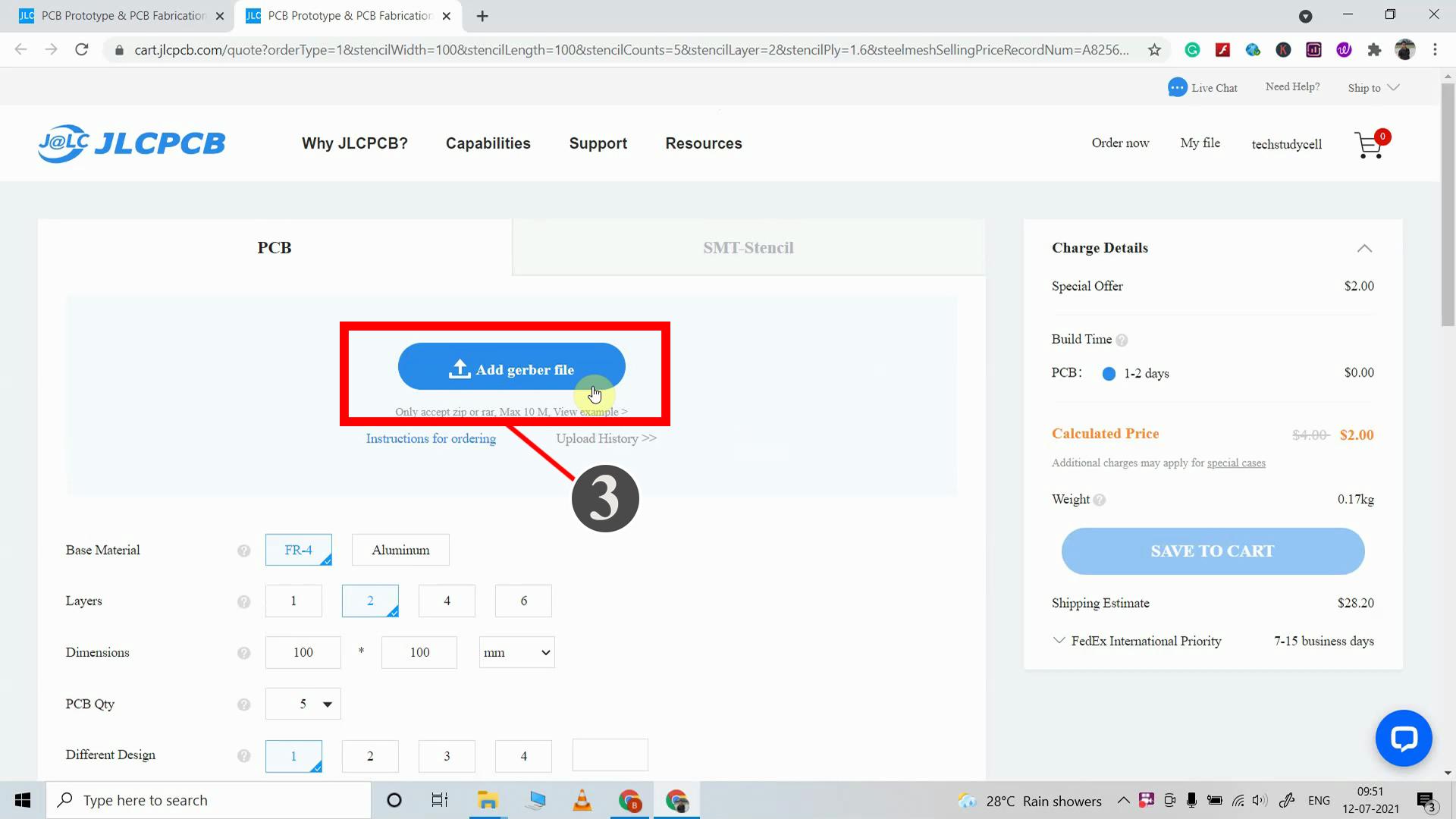
- Click on the "Add your Gerber file" button. Then browse and select the Gerber file you have downloaded.
- Set the required parameter like Quantity, PCB masking color, etc.
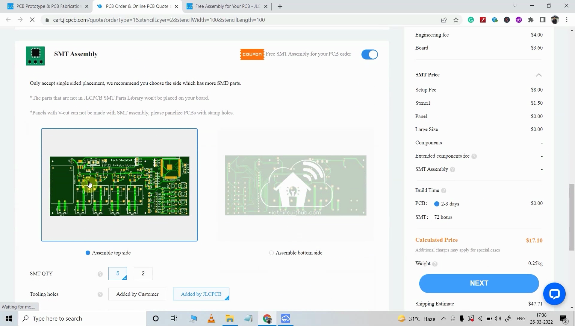
- Select the Assemble side and SMT Quantity.
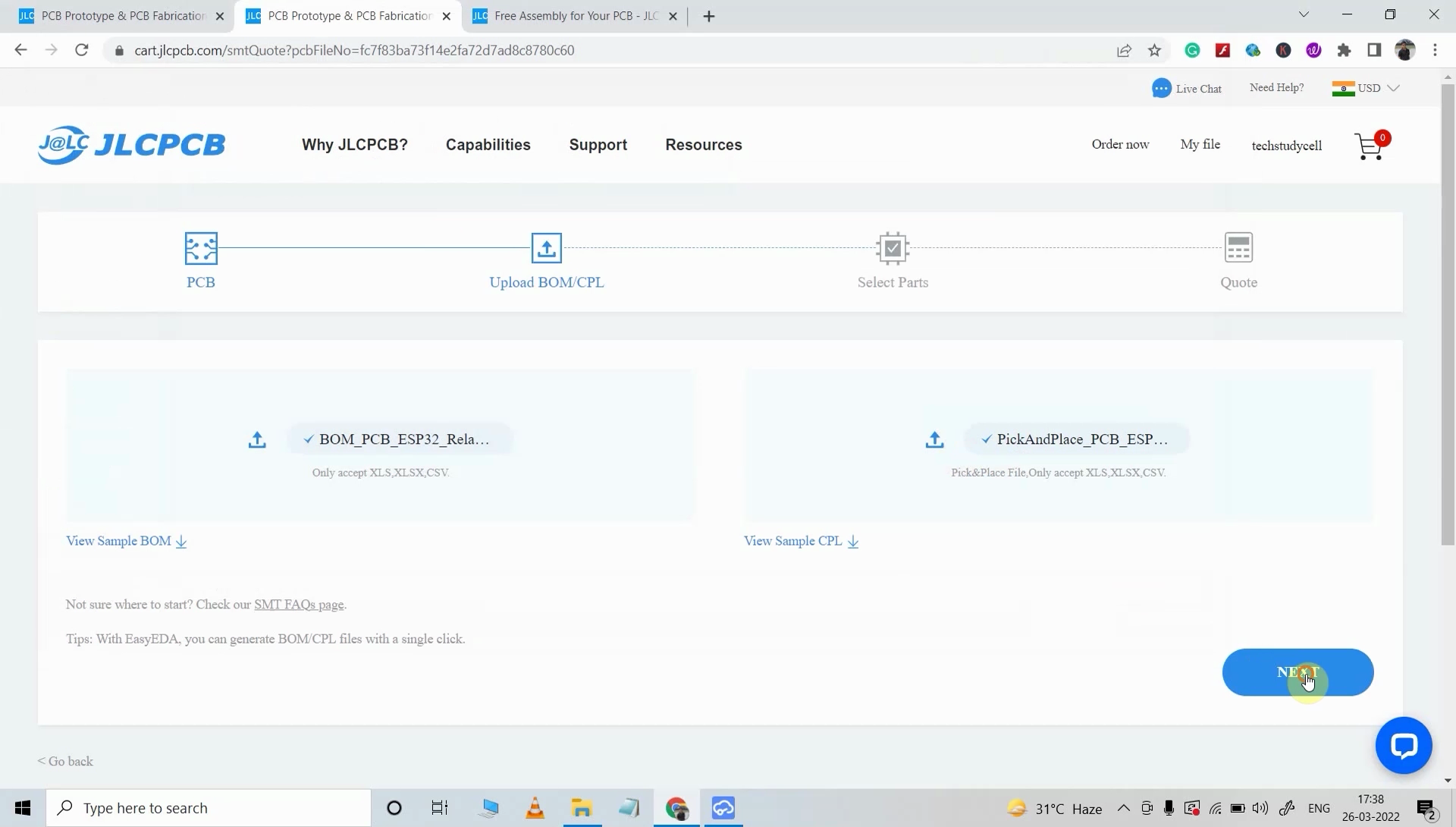
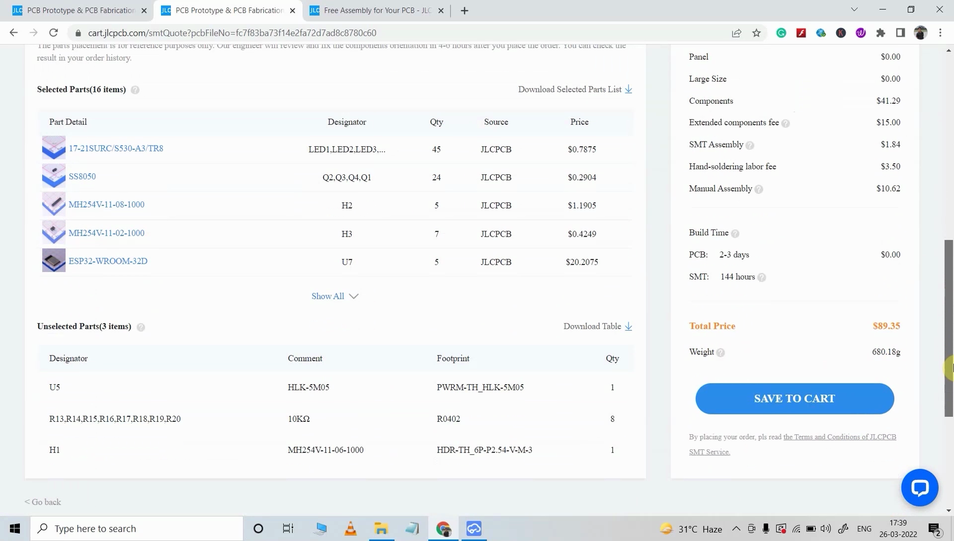
- Now upload the BOM and PickAndPlace files.
- Now confirm all the components which you want to be soldered by SMT services.
- Click on SAVE TO CART button.
Select Shipping Address and Payment Mode
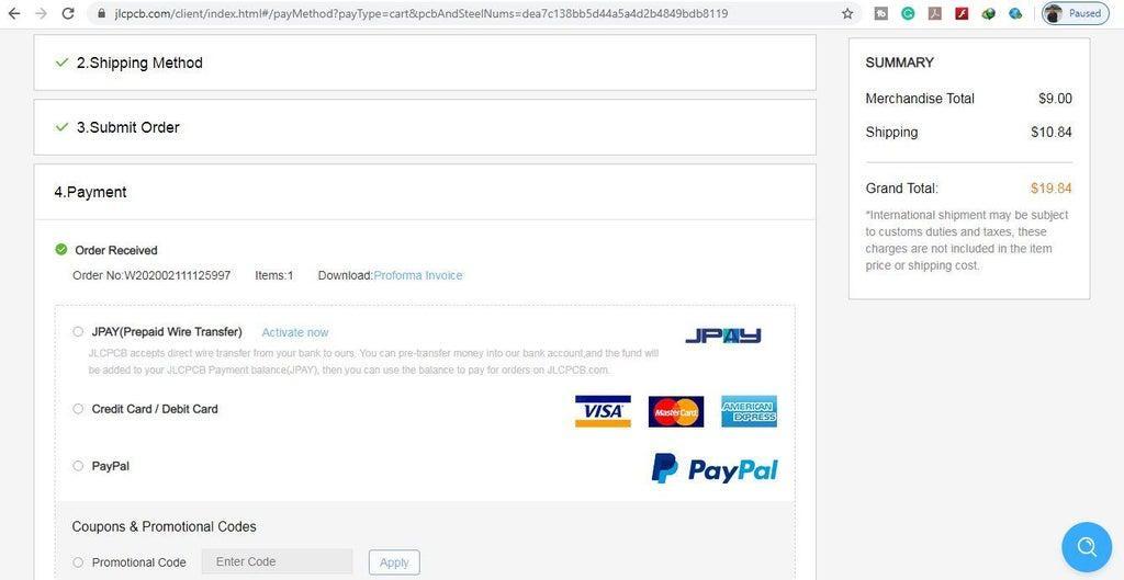
- Type the Shipping Address.
- Select the Shipping Method suitable for you.
- Submit the order and proceed with the payment.
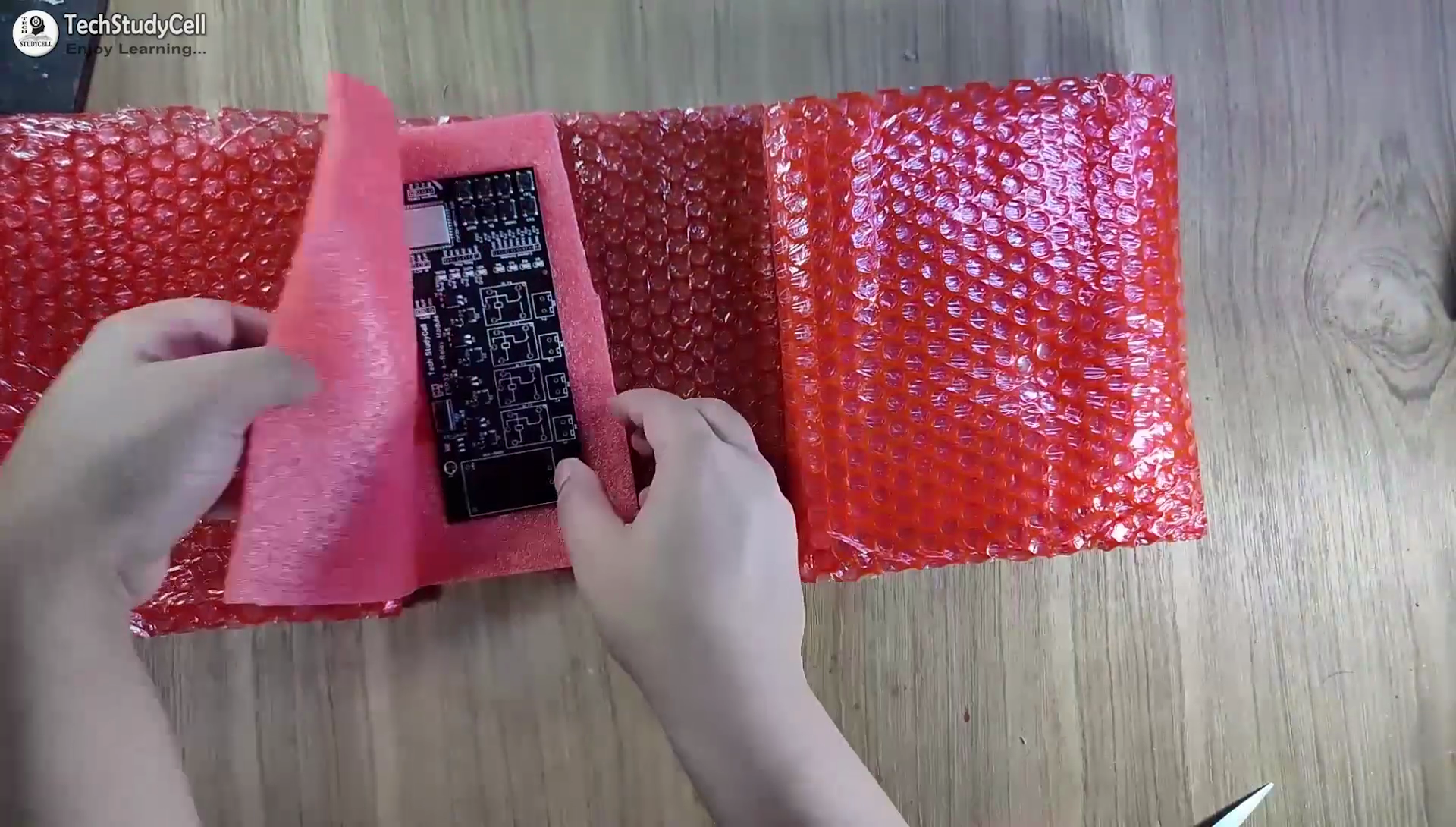
You can also track your order from the JLCPCB. My PCBs took 3 days to get manufactured and arrived within a week using the DHL delivery option.
PCBs were well packed and the quality was really good at this affordable price.
Get the IR Codes (HEX Code) From Remote
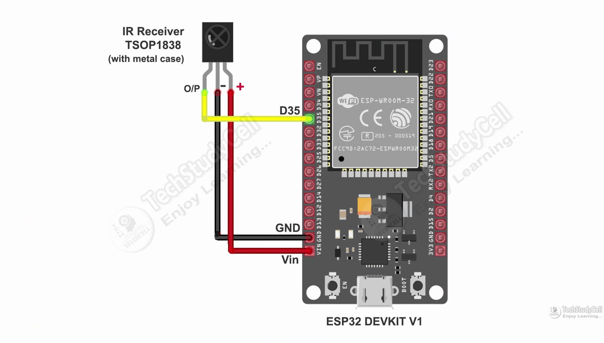
Now, to get the HEX codes from the remote, first, we have to connect the IR receiver output pin with GPIO D35.
And give the 5V across the VCC and GND. The IR receiver must have a metallic casing, otherwise, you may face issues.
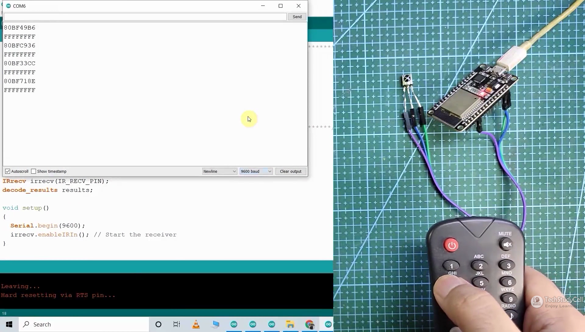
Then follow the following steps to get the HEX codes
- Install the IRremote library in Arduino IDE
- Download the attached code, and upload it to ESP32.
- Open Serial Monitor with Baud rate 9600.
- Now, press the IR remote button.
- The respective HEX code will populate in the serial monitor.
Save all the HEX codes in a text file.
Downloads
Program the ESP32 for This IoT Project
For programming the ESP32, you have to update the Preferences URLs and then install the ESP32 Board 2.0.3 version.
Preferences-- Aditional boards Manager URLs :
https://raw.githubusercontent.com/espressif/arduino-esp32/gh-pages/package_esp32_index.json
Download and install the following libraries in Arduino IDE
- AceButton Library (1.9.2): https://github.com/bxparks/AceButton
- IRremote Library (3.6.1): https://github.com/Arduino-IRremote/Arduino-IRremote
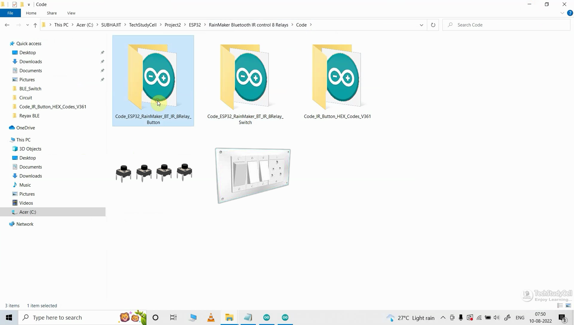
Now open the main sketch (code).
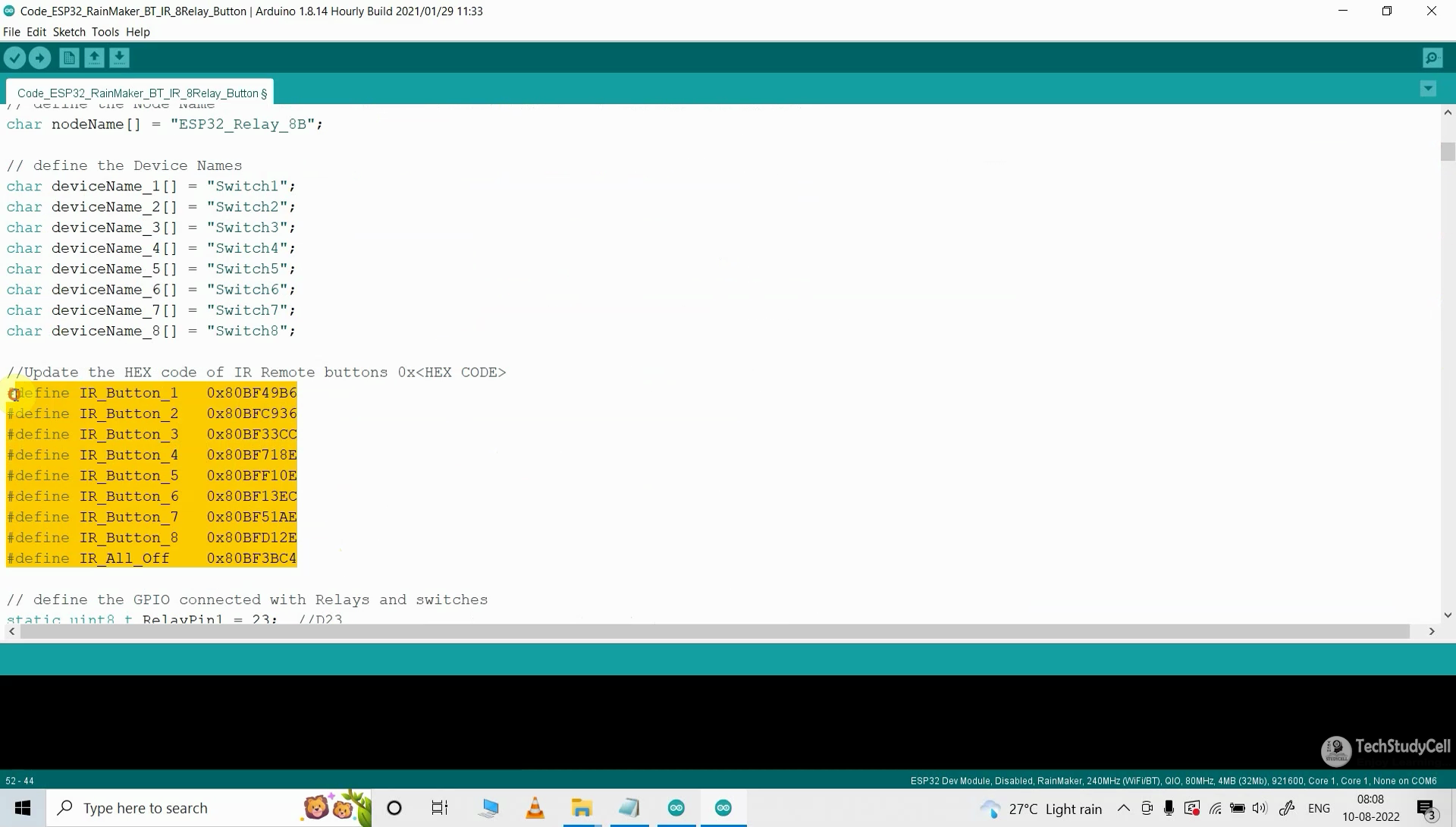
- In the code, you have to update the Device Names (optional)
- Then update the HEX codes of the IR remote as shown in the tutorial video.
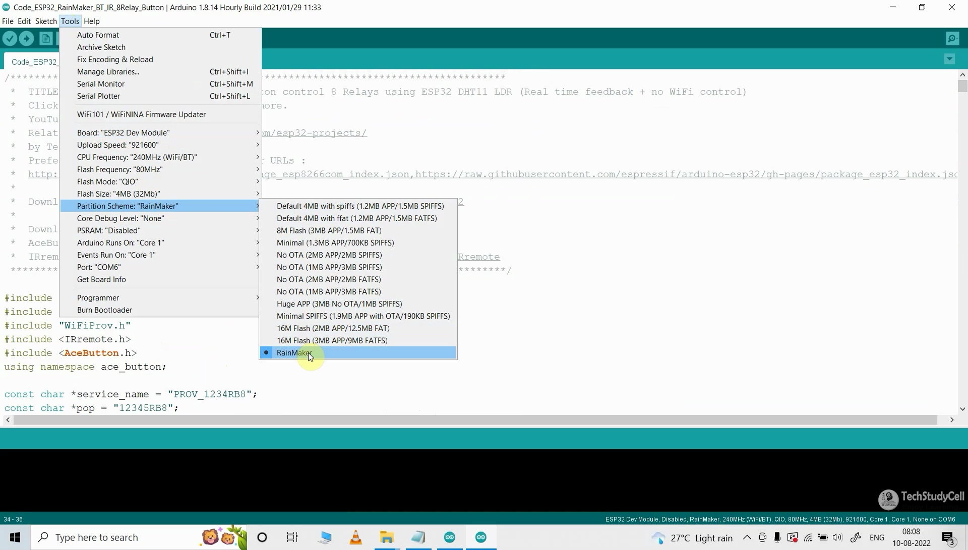
- After that, select the ESP32 DEV Module board, RainMaker Partition Scheme, and proper PORT.
- Then upload the code to ESP32 Board.
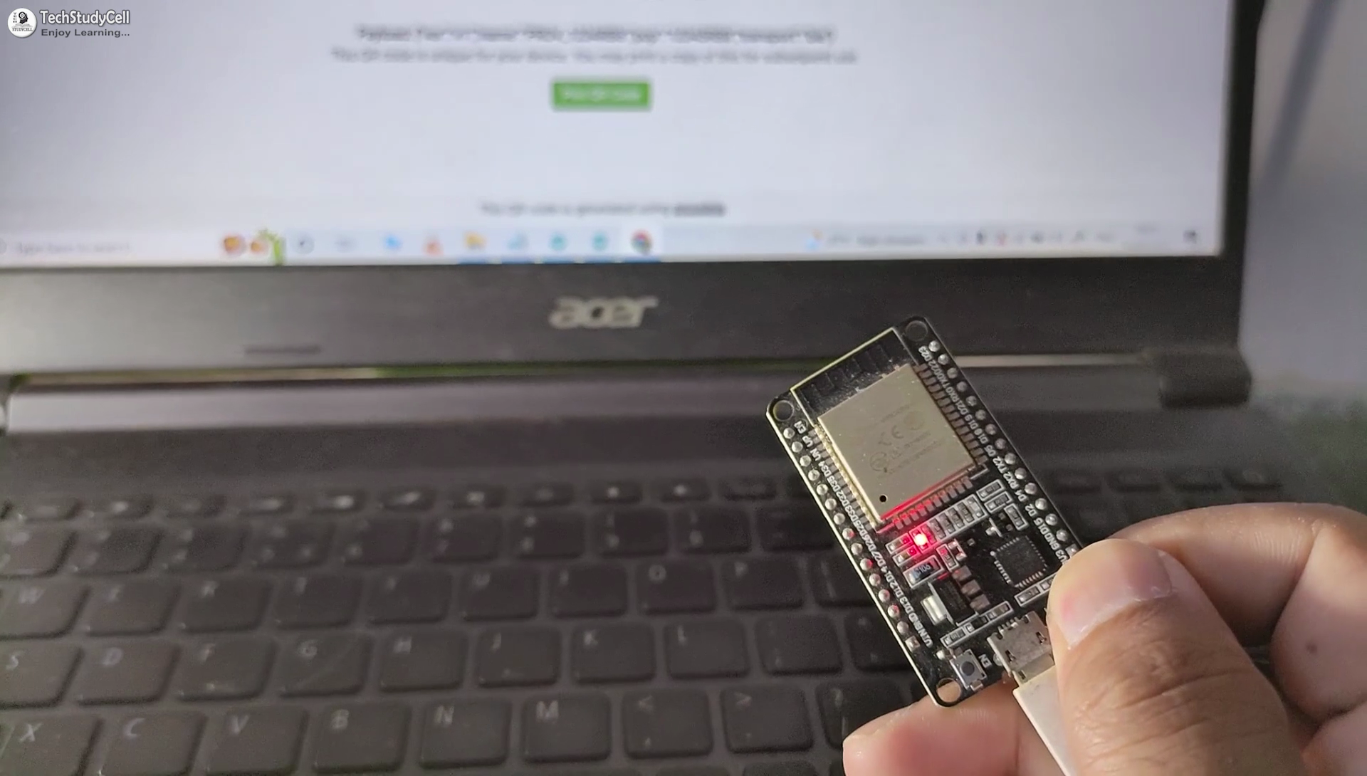
While uploading the code to ESP32, if you use the PCB then you will see the "Connecting....___" text, then press and hold the BOOT button and then press the EN button, after that release both the buttons.
Add Devices in ESP RainMaker App
After programming the ESP32, please follow these steps.
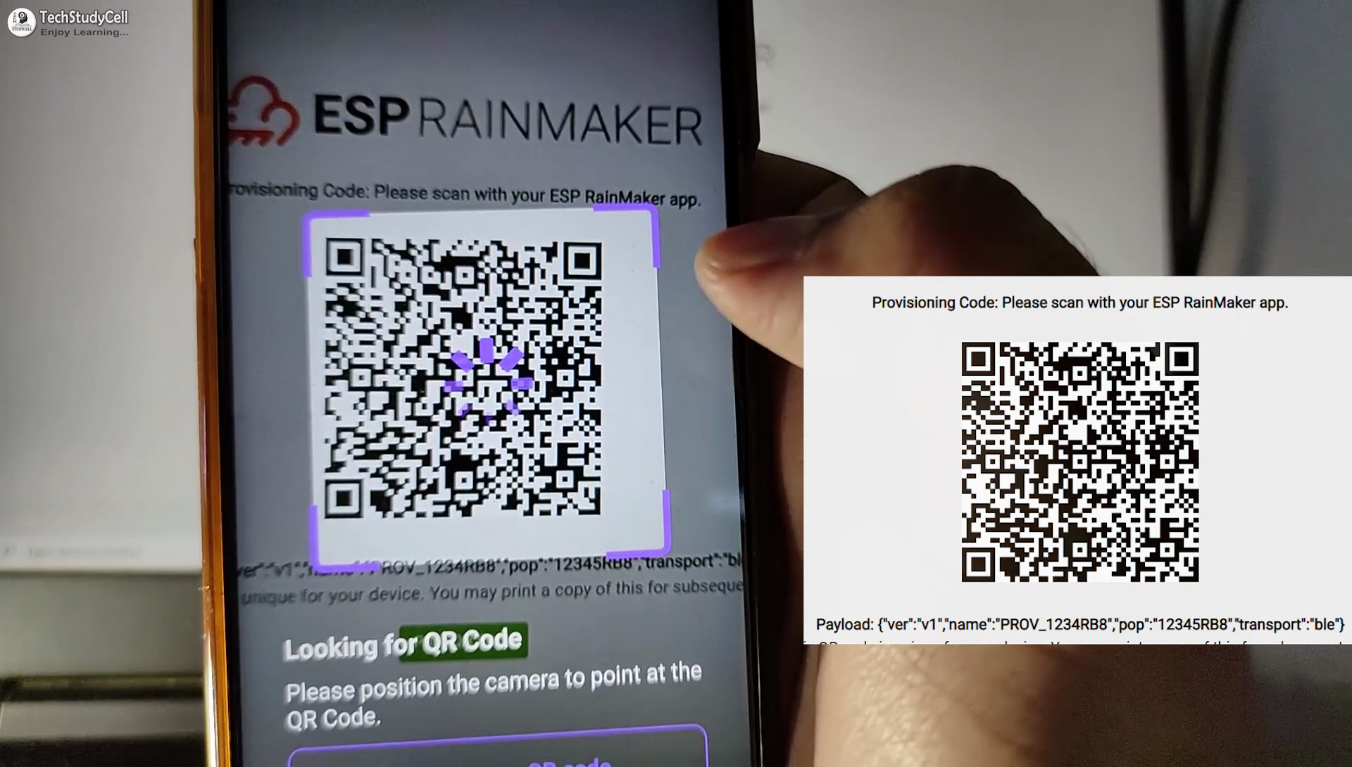
- Press and hold the BOOT button of ESP32 for 4 seconds.
- Turn on Bluetooth and GPS on mobile.
- Open the ESP RainMaker app, and scan the QR code (in the picture).
- Pair with ESP32 BLE and provide the WiFi credentials.
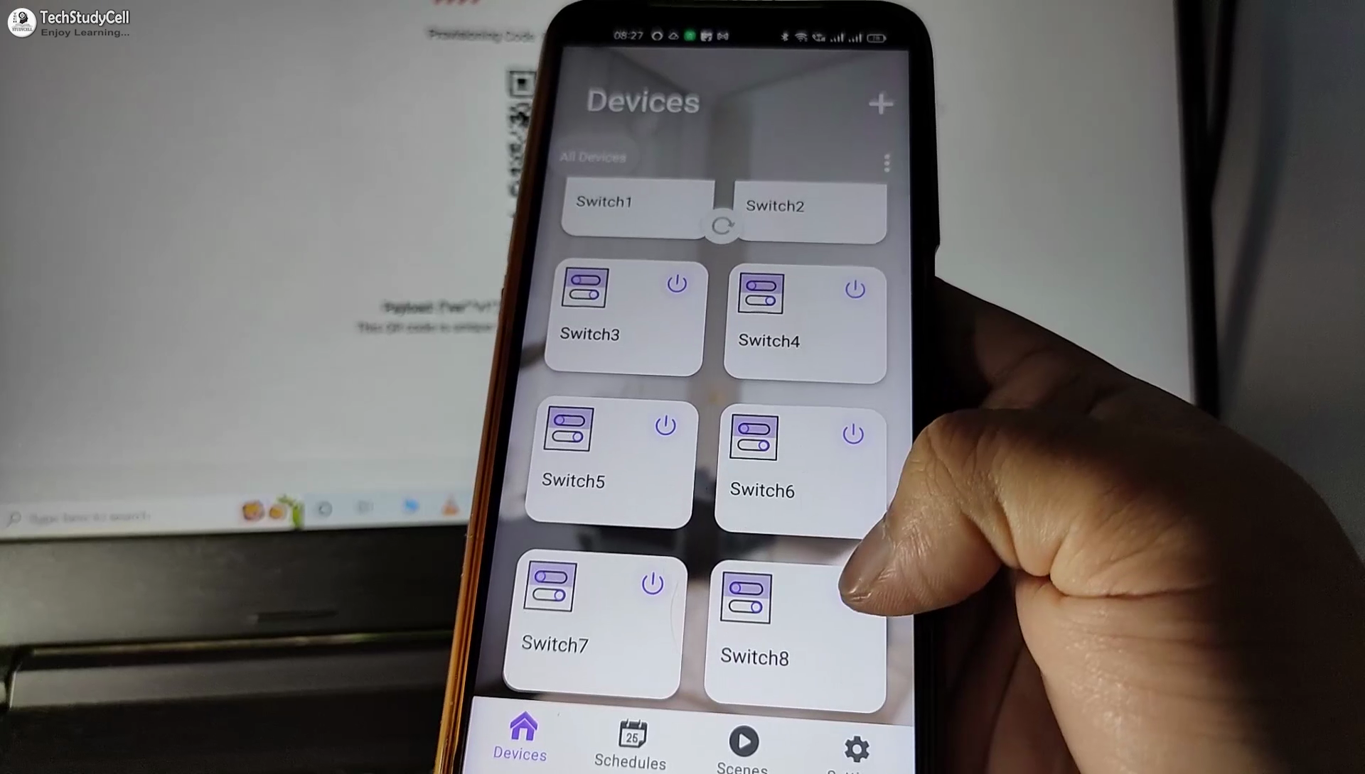
- All the devices will be added to the ESP RainMaker app.
For more detail visit the Official Page of ESP RainMaker.
Link Google Home & Amazon Alexa With ESP RainMaker
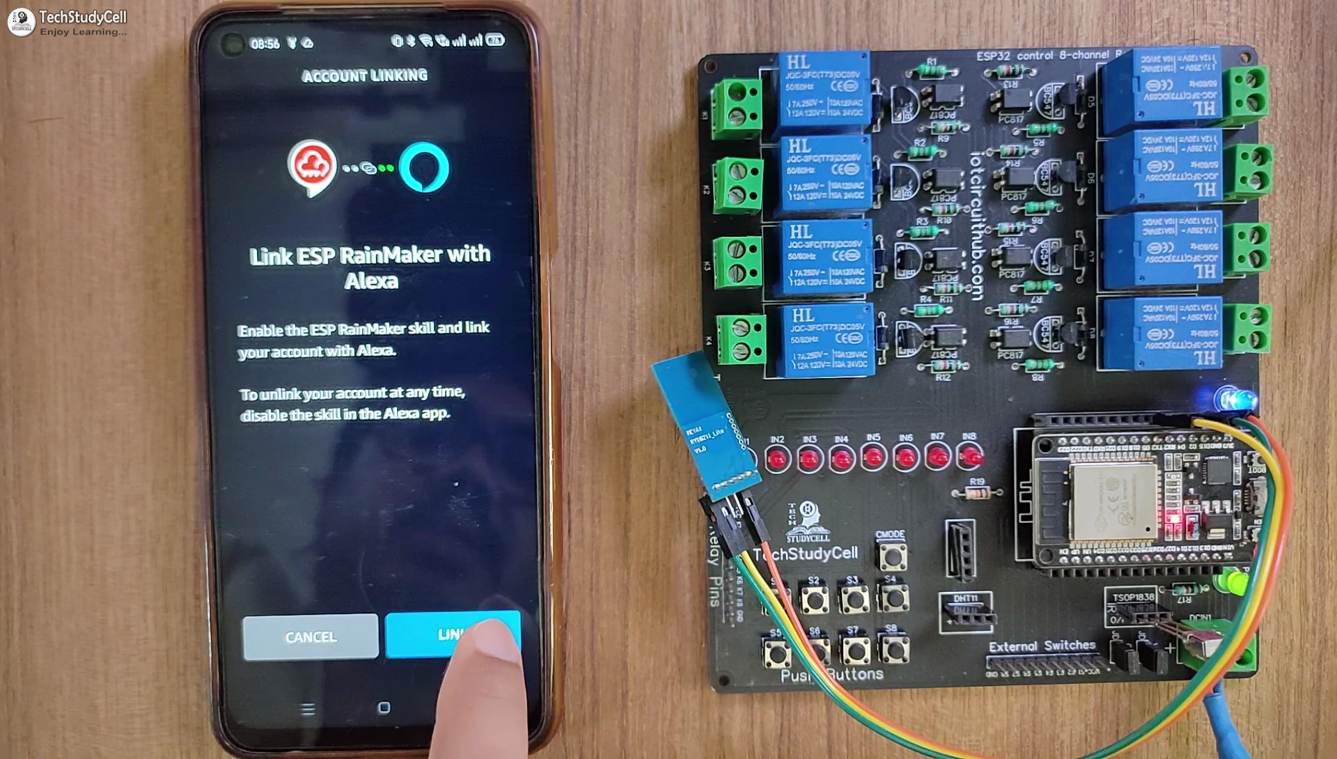
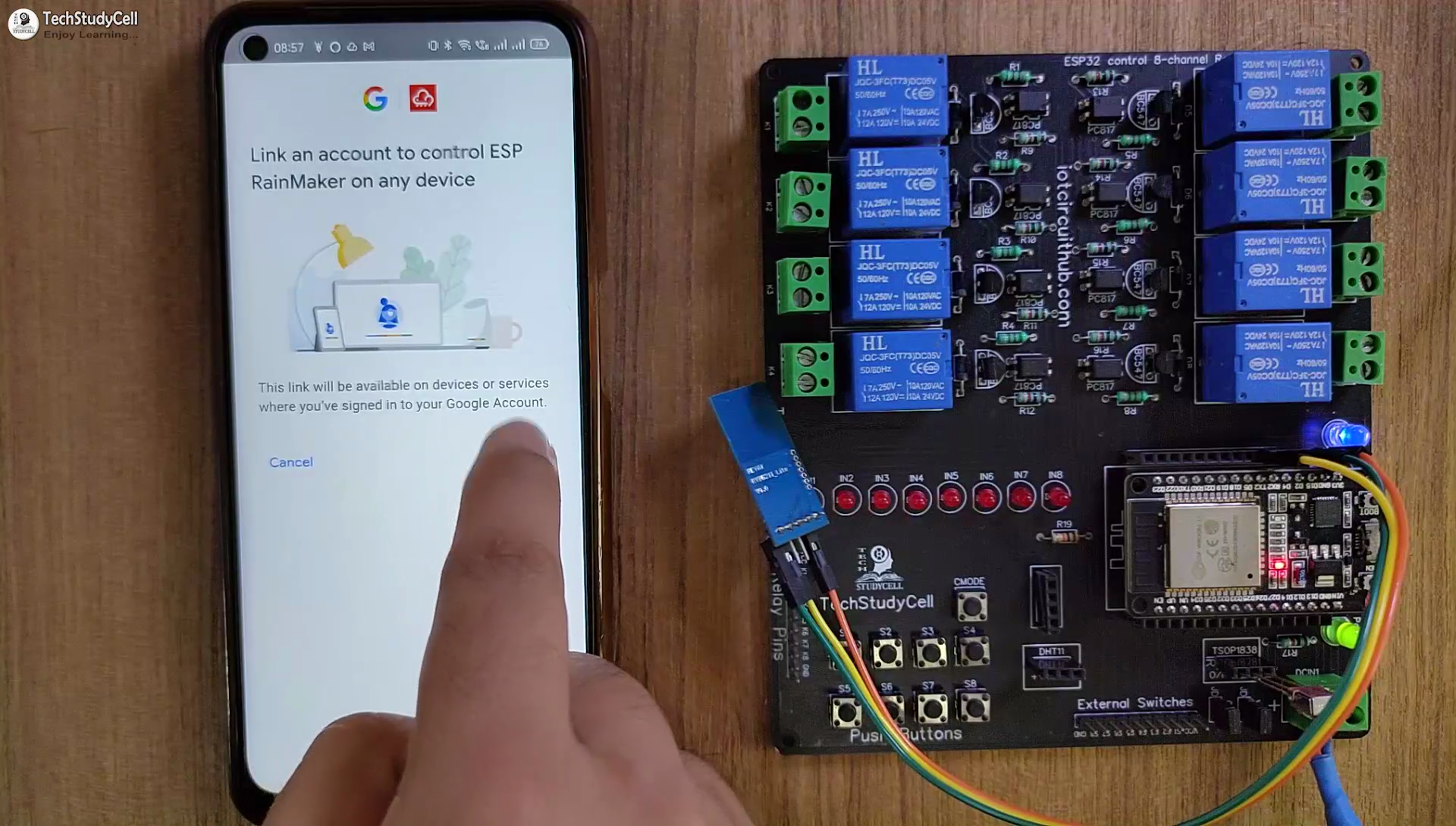
After adding the devices, you can easily link Google Home and Amazon Alexa app with the ESP RainMaker account.
I have shown all the steps in the related tutorial video.
You can control all the appliances and monitor real-time feedback on Google Home and Amazon Alexa app from anywhere in the world.
Finally!! the ESP32 Smart Home System Is Ready

Now you can control your home appliances in a smart way.
So, now you can just ask Google Assistant, "Hey Google, turn off lights", or "Alexa, turn on light". that's it.
I hope you have liked this new IoT-based home automation project. I have shared all the required information for this project.
I will really appreciate it if you share your valuable feedback. Also if you have any queries please write in the comment section.
Thank you & Happy Learning.