ECG Circuit With Arduino Plotting
by cep11579 in Circuits > Arduino
602 Views, 1 Favorites, 0 Comments
ECG Circuit With Arduino Plotting
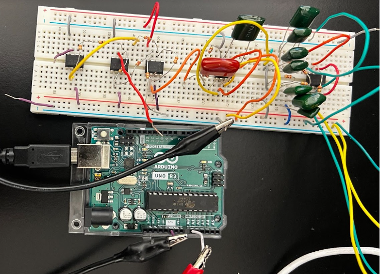
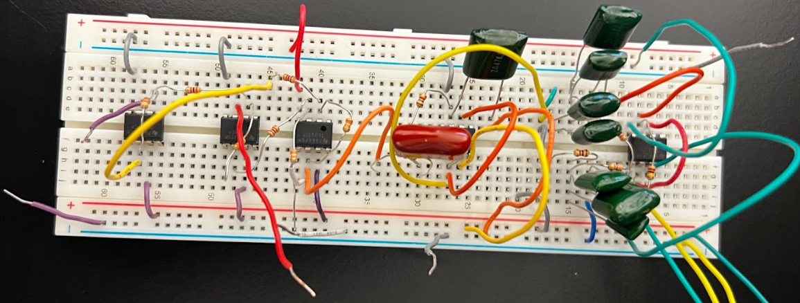
This is an ECG built on a breadboard composed of 3 main filter sections. The sections include an instrumentation amplifier to amplify the electrical signal of the heart, a low pass filter to reduce noise, and a notch filter to eliminate power line interference. This circuit will be attached to an Arduino so that the ECG can be plotted. The purpose of this circuit is to create a small-scale ECG to read the electrical signal of the heart.
Downloads
Supplies
- 1 breadboard
- 5 op-amps
- 1 Arduino with USB cable
- 1 Laptop with Arduino software
- 3 electrodes
- A set of electrical wires
- Resistors: 3 x 2kOhm, 2 x 49kOhm, 2 x 40kOhm, 2 x 1.6kOhm, 2 x 1kOhm, 1 x 236kOhm
- Capacitors: 3 x 470nF, 4 x 168nF
- 2 9V batteries
Build Instrumentation Amplifier
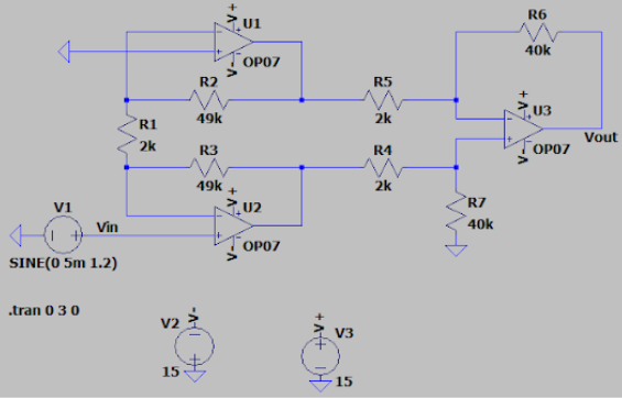
Using the attached image of a circuit diagram as a frame of reference, use the given supplies to build this circuit.
- Place down 3 op-amps about 5 lines apart from each other along the central split of the breadboard, (in order from closest to edge of the breadboard to farthest, referred to as op-amp 1, op-amp 2, op-amp 3).
- Attach the electrodes to the input of op-amp 1.
- Attach wires to each side of both 9V batteries.
- Use the rails of the breadboard to create a positive and negative 9V supply voltage by attaching the positive end of a battery to a rail and the negative end of that battery to ground, while attaching the negative end of a different battery to a different rail and the positive end of that battery to ground.
- Attach wires from the supply voltage rails to the respective supply voltage inputs of all 3 op-amps.
- Attach a wire from V+ of op-amp 2 to ground.
- Attach a 2kOhm resistor from V- of op-amp 1 to V- of op-amp 2.
- Attach a 49kOhm resistor from V- of op-amp 1 to Vout of op-amp 1.
- Attach a 49kOhm resistor from V- of op-amp 2 to Vout of op-amp 2.
- Attach a 2kOhm resistor from Vout of op-amp 1 to V+ of op-amp 3.
- Attach a 2kOhm resistor from Vout of op-amp 2 to V- of op-amp 3.
- Attach a 40kOhm resistor from V+ of op-amp 3 to ground.
- Attach a 40kOhm resistor from V- of op-amp 3 to Vout of op-amp 3.
- Attach a wire to Vout to be used in the next step.
Build Low Pass Filter
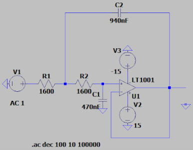
Using the attached image of a circuit diagram as a frame of reference, use the given supplies to build this circuit.
- Place down 1 op-amp about 5 lines past op-amp 3 from Step 1 along the central split of the breadboard, (referred to as op-amp 4).
- Attach wires from the supply voltage rails to the respective supply voltage inputs of op-amp 4.
- Attach the wire from the end of Step 1 in series with a 1.6kOhm resistor.
- Attach the resistor in series with a 1.6kOhm resistor that connects to V+ of op-amp 4.
- Attach a 470nF capacitor from V+ of op-amp 4 to ground.
- Attach two 470nF capacitors in parallel, then attach them from the 1.6kOhm - 1.6kOhm connection point to Vout of op-amp 4.
- Attach V- of op-amp 4 to Vout of op-amp 4.
- Attach a wire to Vout to be used in the next step.
Build Notch Filter
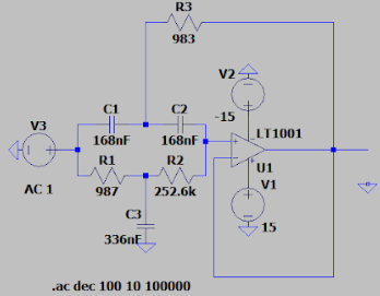
Using the attached image of a circuit diagram as a frame of reference, use the given supplies to build this circuit.
- Place down 1 op-amp about 5 lines past op-amp 4 from Step 2 along the central split of the breadboard, (referred to as op-amp 5).
- Attach wires from the supply voltage rails to the respective supply voltage inputs of op-amp 5.
- Attach the wire from the end of Step 2 in series with a 1kOhm resistor.
- Attach the resistor in series with a 236kOhm resistor that connects to V+ of op-amp 5.
- Attach two 168nF capacitors in parallel, then attach them from the 1kOhm - 236kOhm connection point to ground.
- Attach a 168nF capacitor to the Step 2 wire - 1kOhm connection point.
- Attach a 168 nF capacitor to V+ of op-amp 5 and attach it in series with the 168nF capacitor that is attached to the Step 2 wire - 1kOhm connection point.
- Attach a 1kOhm resistor from the 168nF - 168nF connection point to Vout of op-amp 5.
- Attach V- of op-amp 5 to Vout of op-amp 5.
- Attach a wire to Vout to be used in the next step.
The combined circuit is now complete.
Plotting With Arduino

- Install proper Arduino software on laptop.
- Connect Arduino to laptop using USB cable.
- Attach the wire from the end of Step 3 to a slot in the Arduino.
- Attach a wire from a different slot in the Arduino to ground.
- Attach one electrode to each wrist to measure the electrical signal of the heart.
- Attach one electrode to either ankle to act as ground.
- Code a plotting system in Arduino software to properly display the signal.
- Begin measurement and watch the ECG as it is plotted on the laptop.
The combined circuit with Arduino is now complete.