E-GOR the Retro Robot
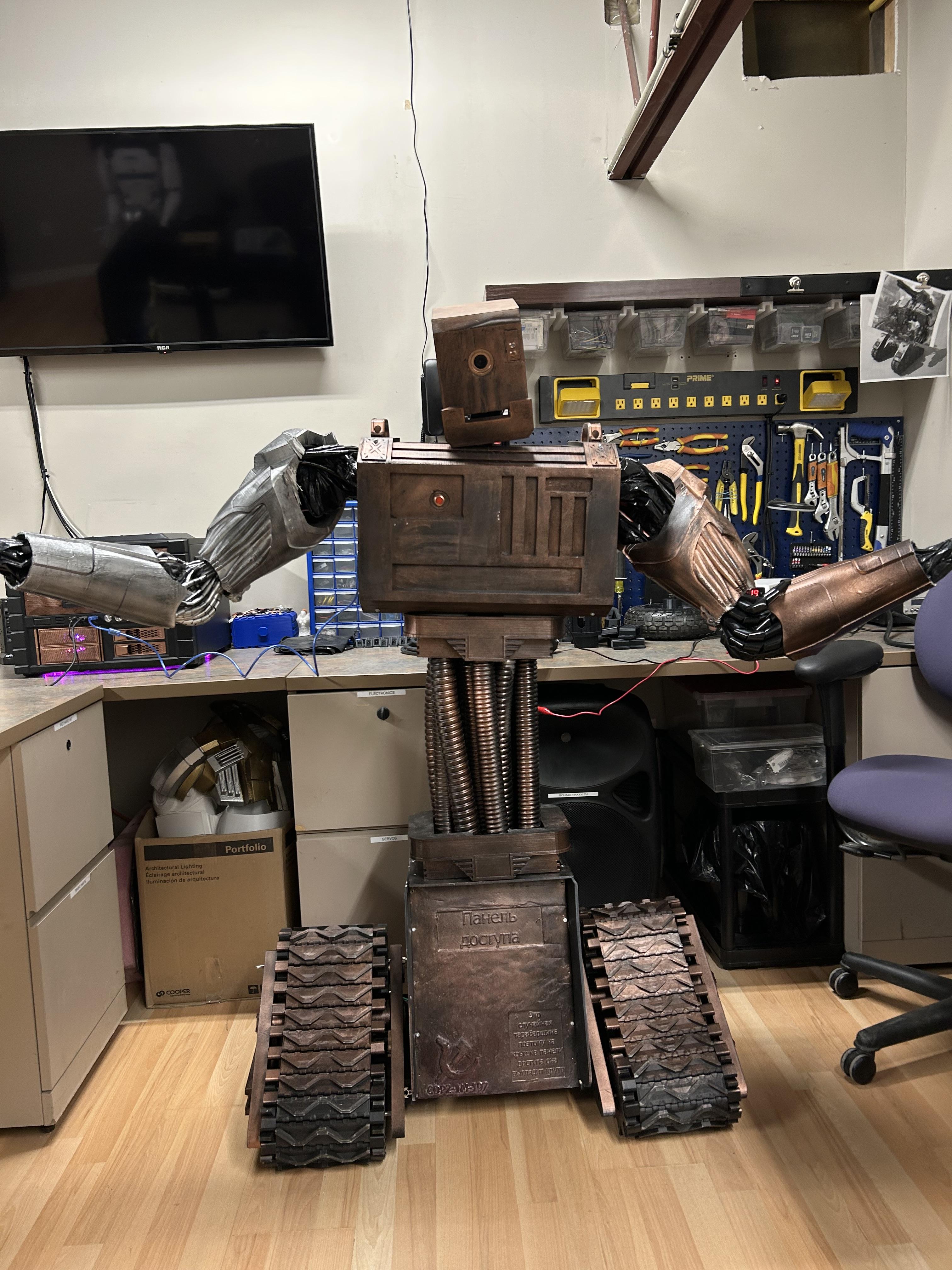


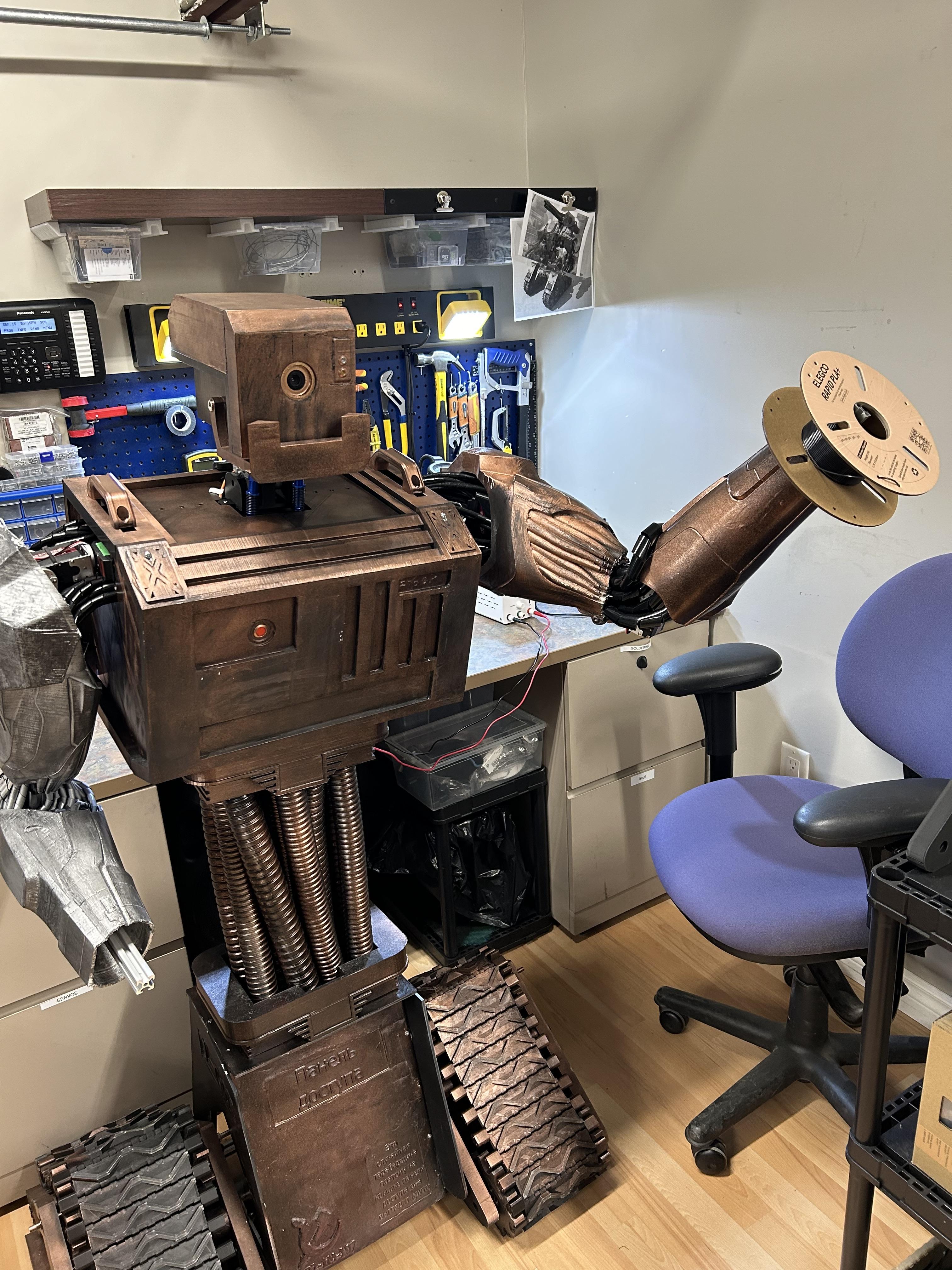

This is E-G0R, a retro styled robot that can be programmed for versatile use.
Supplies
3D Printable Parts:
Servos:
(x4) 150 kg/cm 12V 270 degree dual shaft servos
(x2) 150 kg/cm 12V 270 degree servos
(x2) 80kg/cm 6V 270 degree servos
(x5) MG996R 15kg/cm 6V 180 degree servos
Mechanical:
(x2) 2020 Extrusion (200mm)
(x10) 2020 Extrusion (300mm)
(x1) 2020 Extrusion (400mm)
(x1) 2020 Extrusion (1000mm)
(x10) 2020 Extrusion L-Brackets
(x16) M2.5 Heat Inserts
(x1) M3x12 Screw
(x4) M3x20 Screws
(x25-50) M3x8 Screws
(x2) M3 Nuts
(x25-50) M3 T-Nuts
(x4) M4x16 Screws
(x4) M4 Nuts
(x1) M8x150mm Hollow Rod
(x2) 8mm (Inner Diameter) Shaft Collar
(x1) 6" Round Lazy Susan Bearing
(x1) 30x42x7mm Bearing
(x4) KP08 Bearings (8mm I.D Bearing with set screws)
(x2) RC Servo Shocks (Length range: 100-130mm) or linkage rods with adjustable length (100-130mm)
Electronics:
(x2) 6mm 6V Indicator Lights
(x1) PCB Board and some male header pins to make a Servo bus/board
(x1) PCA9685 12-Channel Servo Board
(x1) Arduino Uno
The Head

.png)


.png)
.png)
.png)
Print all the parts for the head.
I used DryDex Spackle to fill all the layer lines and give the head a textured effect.
I then primed, painted and used some graphite powder to give it a weathered look and sealed it with some clear coat.
(I spray-painted the surface with Rustoleum black paint+primer & added a light coat of copper spray paint just after applying the black paint. Since the two paints are still wet, some parts mix, while some parts separate, creating a weathered retro look).
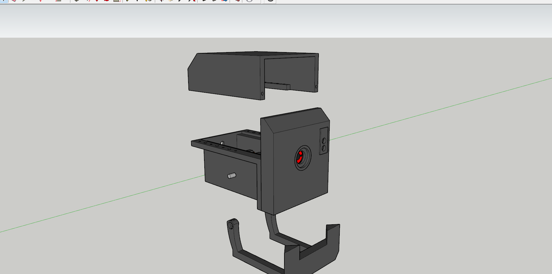
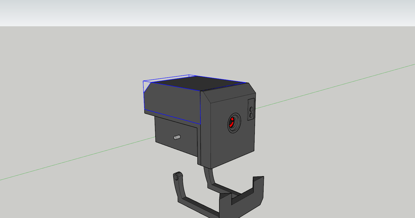
Assemble the head as shown and secure the pieces using M3/M4 bolts with brass heat inserts (or if the holes are small enough, you can manually thread/tap them)
Measure and cut and 8mm(O.D) rod to 120mm so it's long enough to slide through Head Base and the Jaw. Ensure it can spin smoothly (if it can't drill out the holes a bit). Once you have the rod partly through the Head Base, slide the Jaw Shaft Gear on the rod and then push the rest of the rod out.
Press fit the 8mm Shaft Collars in the Jaw and slide the rod in. (You may have to make a small notch to access the shaft collars set screw and secure it to the rod). Once everything is tightened down (including the gear) ensure when you manually turn the shaft gear it moves the jaw.
Set your MG996R servo to 0/180 degrees, depending on orientation (the servo should spin clockwise if you're going to set your jaw to fully closed as a default position). Add the Jaw Drive Gear to the servo, then fully close the jaw & add the servo to the slot in the Head Base. Test your servo to ensure it moves the jaw correctly. (I had some slippage in my gears, but I used a zip tie to act as a tensioner).
Chest
.png)
.png)
.png)
.png)
.png)
.png)
.png)
.png)

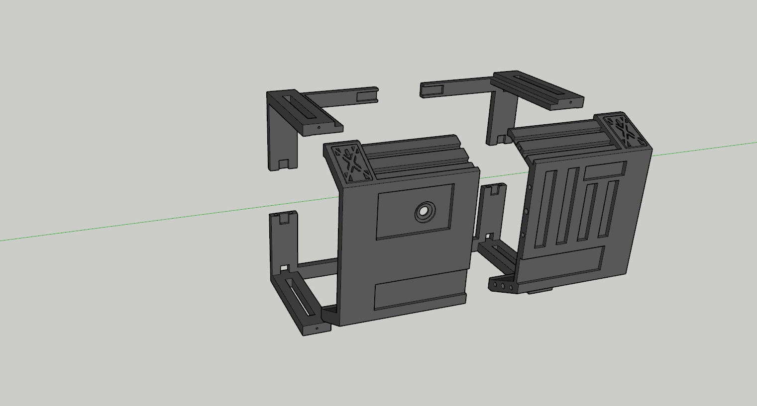
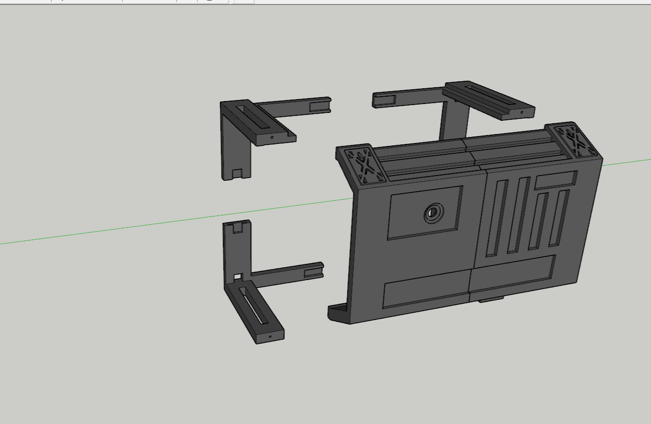
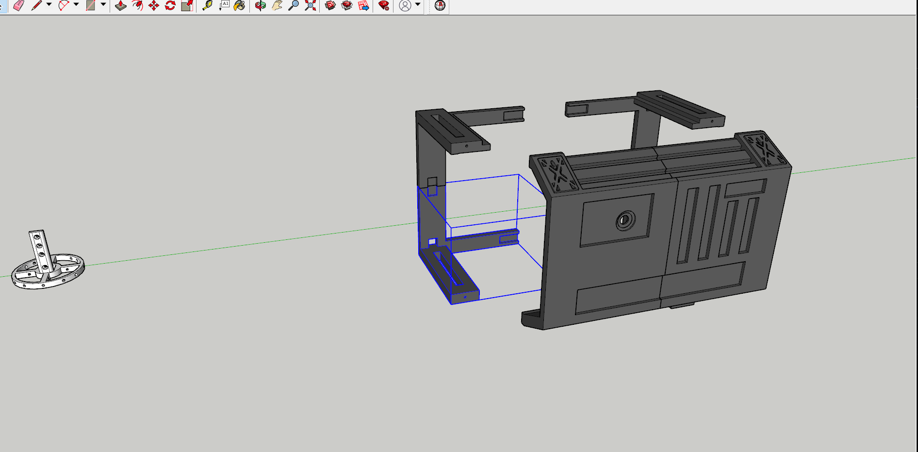
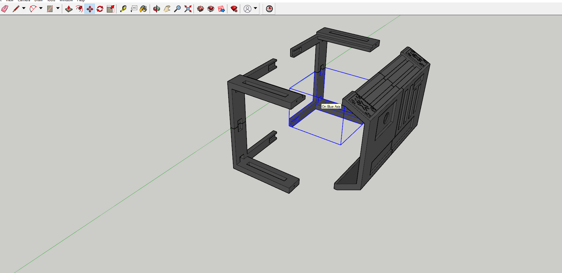
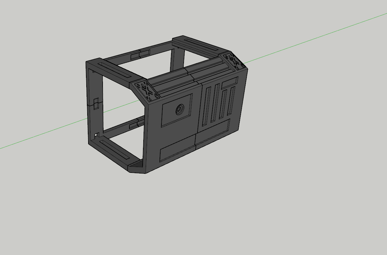
Print the chest pieces and assemble them as shown.
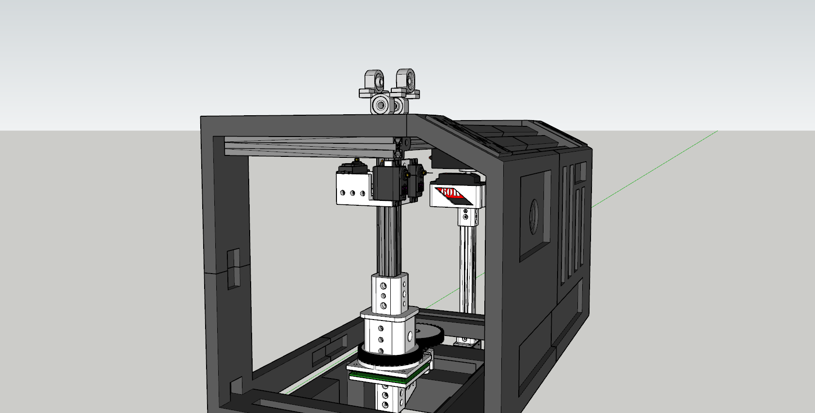
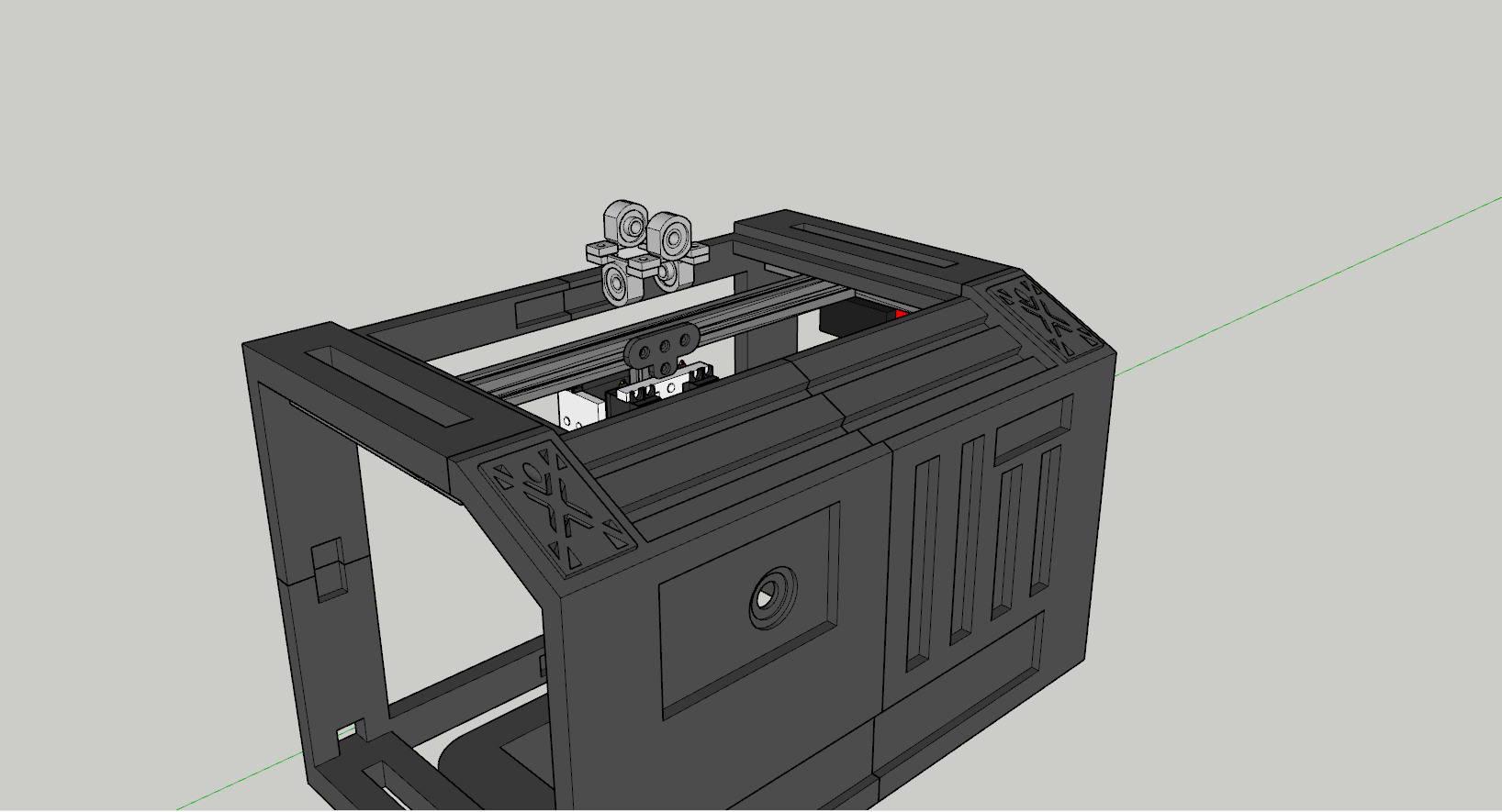
Add the (2) 2020x200mm Extrusion pieces to the top slots of the rear chest panels (as shown in the picture above) as they will be used to mount the servos for the arm mechanism and act as a brace to hold the 400mm extrusion for the neck.
I welded the Chest Panels together and all the Rear Panels together and used some long machine screws to join the front chest to the back. (I did this in case I had to service the neck mechanism, but I can reach everything without removing the front chest plate. It's up to you, if you want to make the chest all one piece or have the front piece removable).
You can now add the handles using some 20mm M3 screws, washers and T-Nuts. This helps secure the extrusion and acts as a cool aesthetic (Plus, you'll be able to grab your bot by the handles to separate it from its torso later on).
Neck Mechanism


.png)
.png)
.png)
.png)


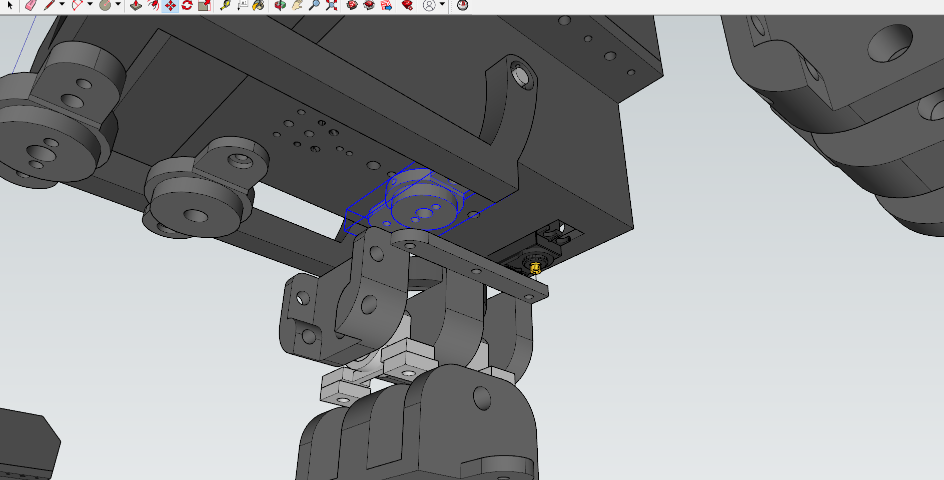
Print and assemble.
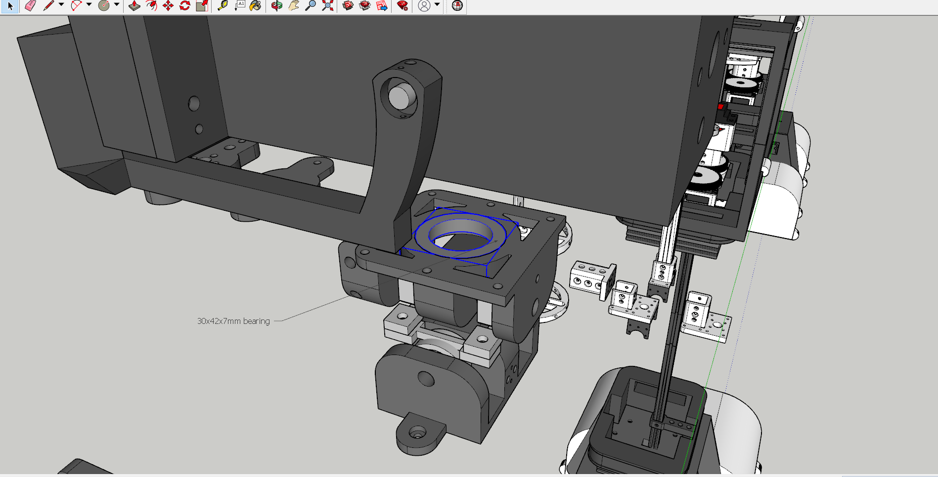
Neck Bearing Seat (30.4mm H-10mm) gets mounted to the bottom of the head using M3 heat inserts and M3 screws.
When inserting the Bearing seat into the bearing, it should be a tight fit (this will prevent the head from flying off) However, if it's not a tight fit, you should add a small nut/bolt through the bearing seat and neck top to act as a retainer, so the head won't lift/fly off.
For the neck rotation mechanism, I took the rack gear, heated it up to arc it, then attached it to Neck Top. I did this as a "Temporary" mechanism to test; but it's working, so it's going to stay for now.
Base
.png)
.png)
.png)


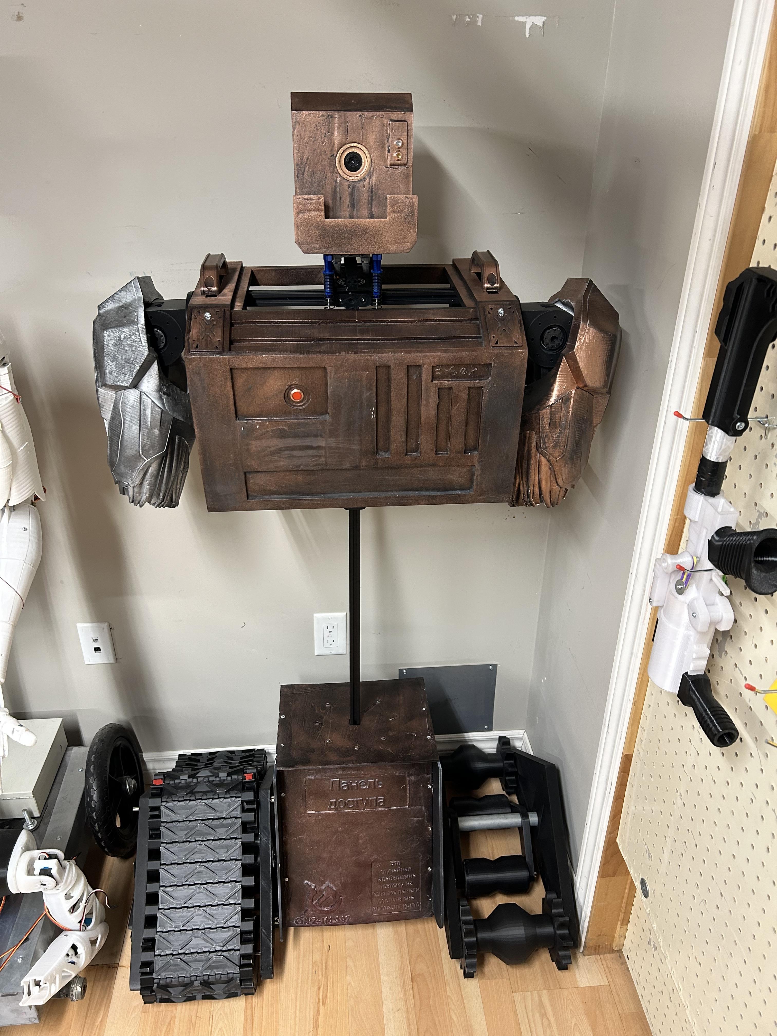
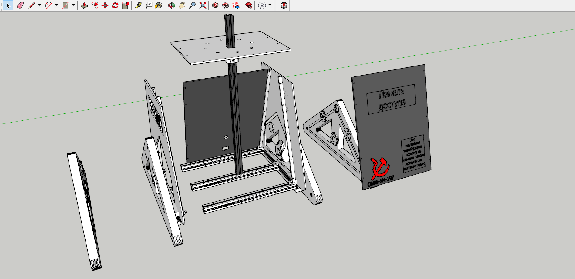
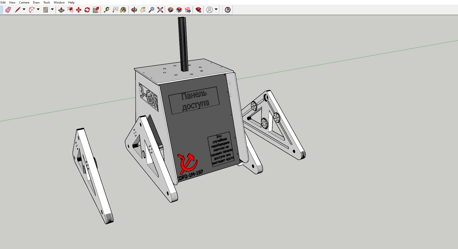
Print, paint, and assemble the parts as shown. Refer to the tank tread model for assembly (Or this video since mine's just a scaled up version of Let's Print's model with a few modifications)
To drive the tank treads, use a high torque, 8mm shaft motor, and some 8mm Shaft couplers to join the motor to the 8mm drive rod you installed on your treads. (If your 8mm rod spins in place, use a tek (self drilling) screw to go through the drive gear and the 8mm rod. This will prevent the rod from spinning in place, & in turn spin the drive gear along with it). You can also use a couple old chucked drills to drive the treads if you have some lying around.
Torso


.png)
.png)
.png)
.png)
.png)
.png)
.png)
.png)
.png)
.png)
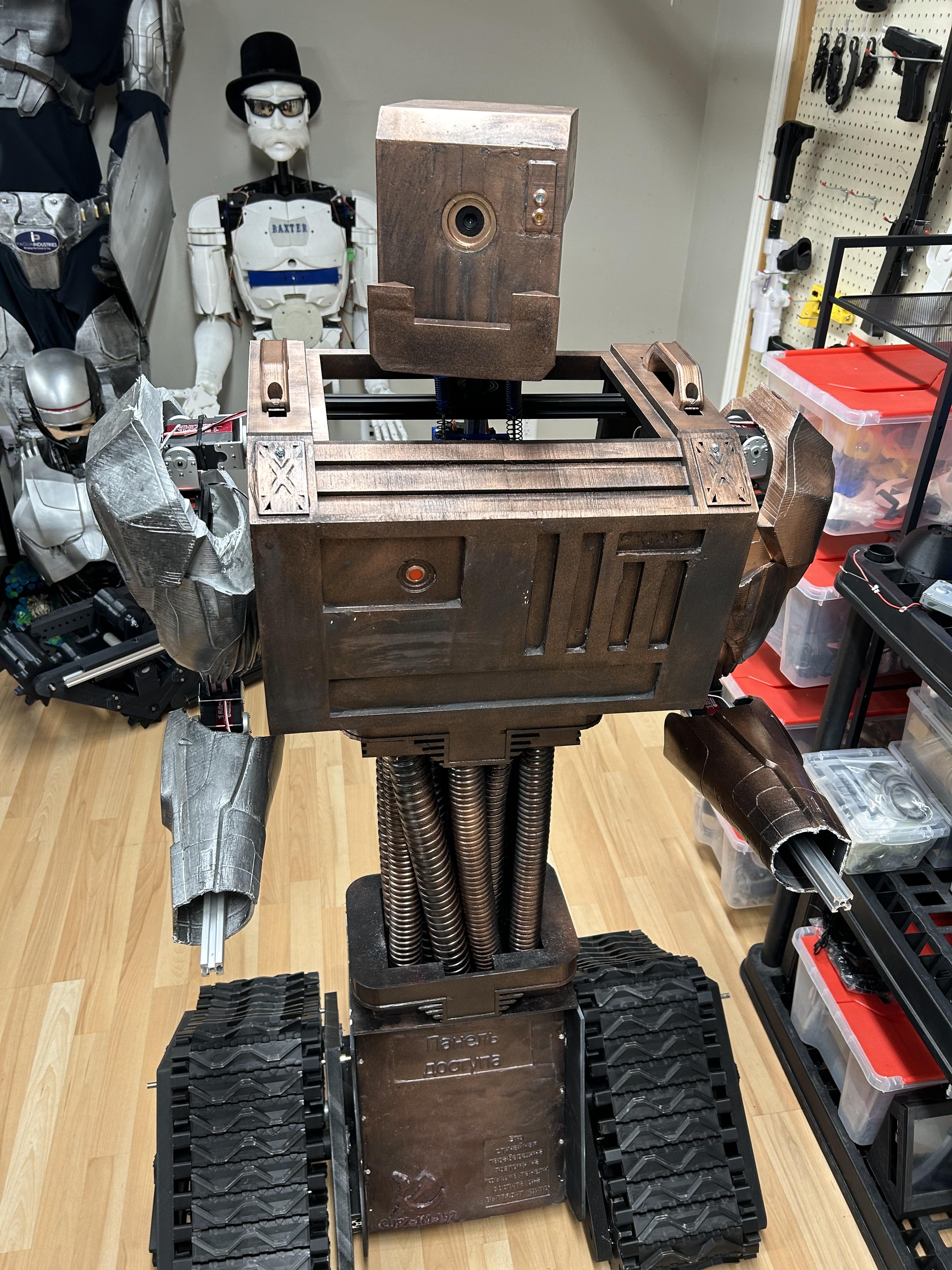
Print Torso-Lower and Torso-Lower Top.
Sand, Prime and Paint.
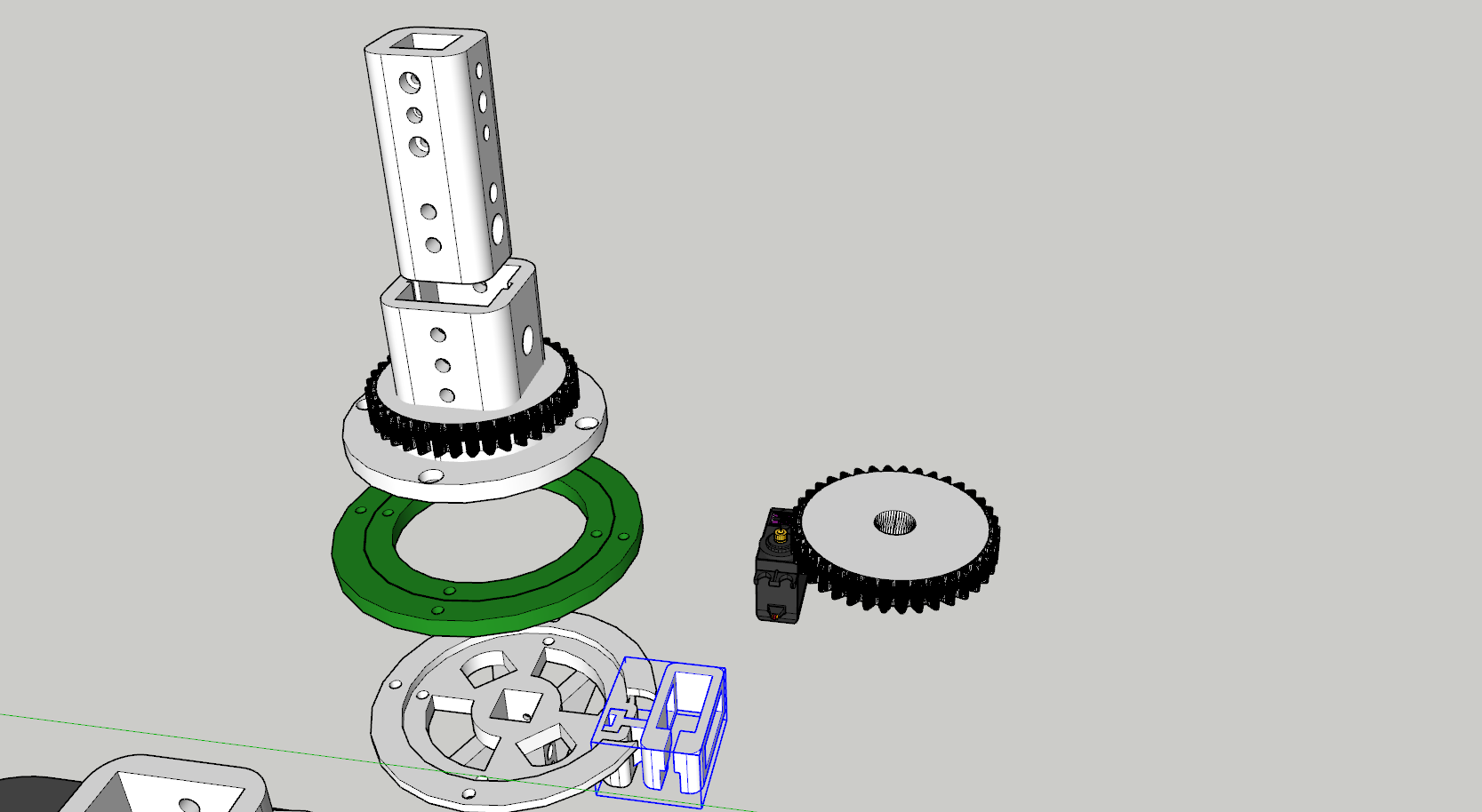
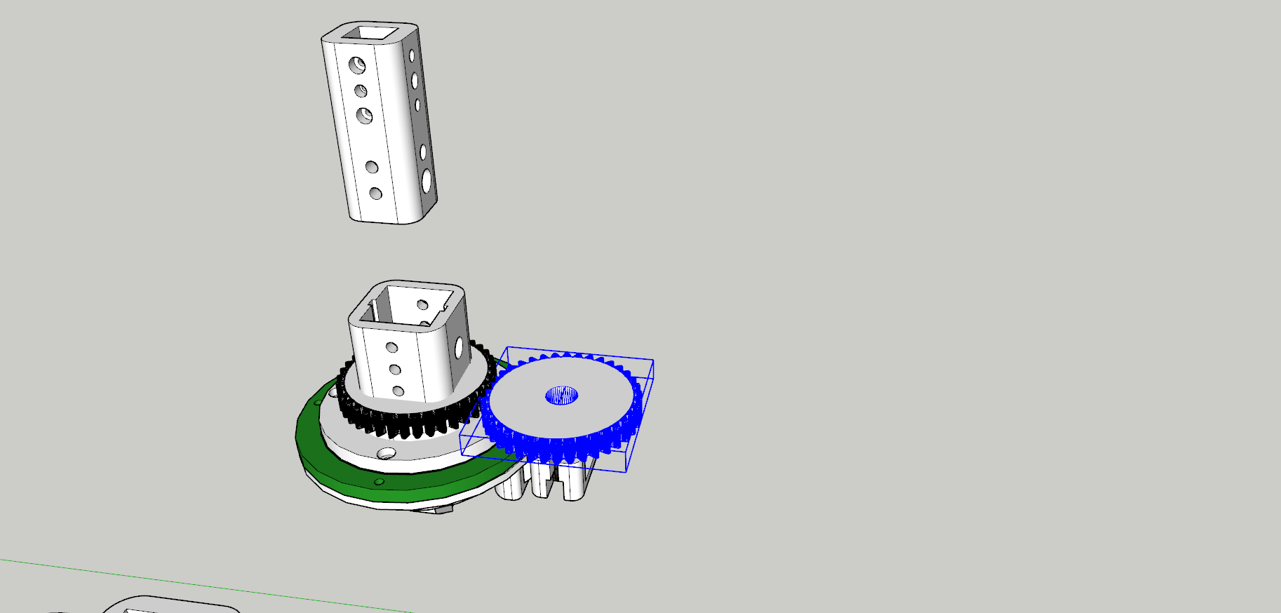
Then slide the Torso Lower down the 1000mm 2020 Extrusion and slide Torso-Lower Top on and bolt near the top, leaving room to mount the Torso-Geared Bearing Mount.
To cover the 2020 Extrusion I used some scrap BX (Armoured Cable) Sheaths I had, painted them and sandwiched them between the Torso-Lower pieces.
(The empty sheaths will also act as a raceway for all the wires to run through).
Print the Torso Bearing Top/Bottom with a min 6 walls and min 20% infill.
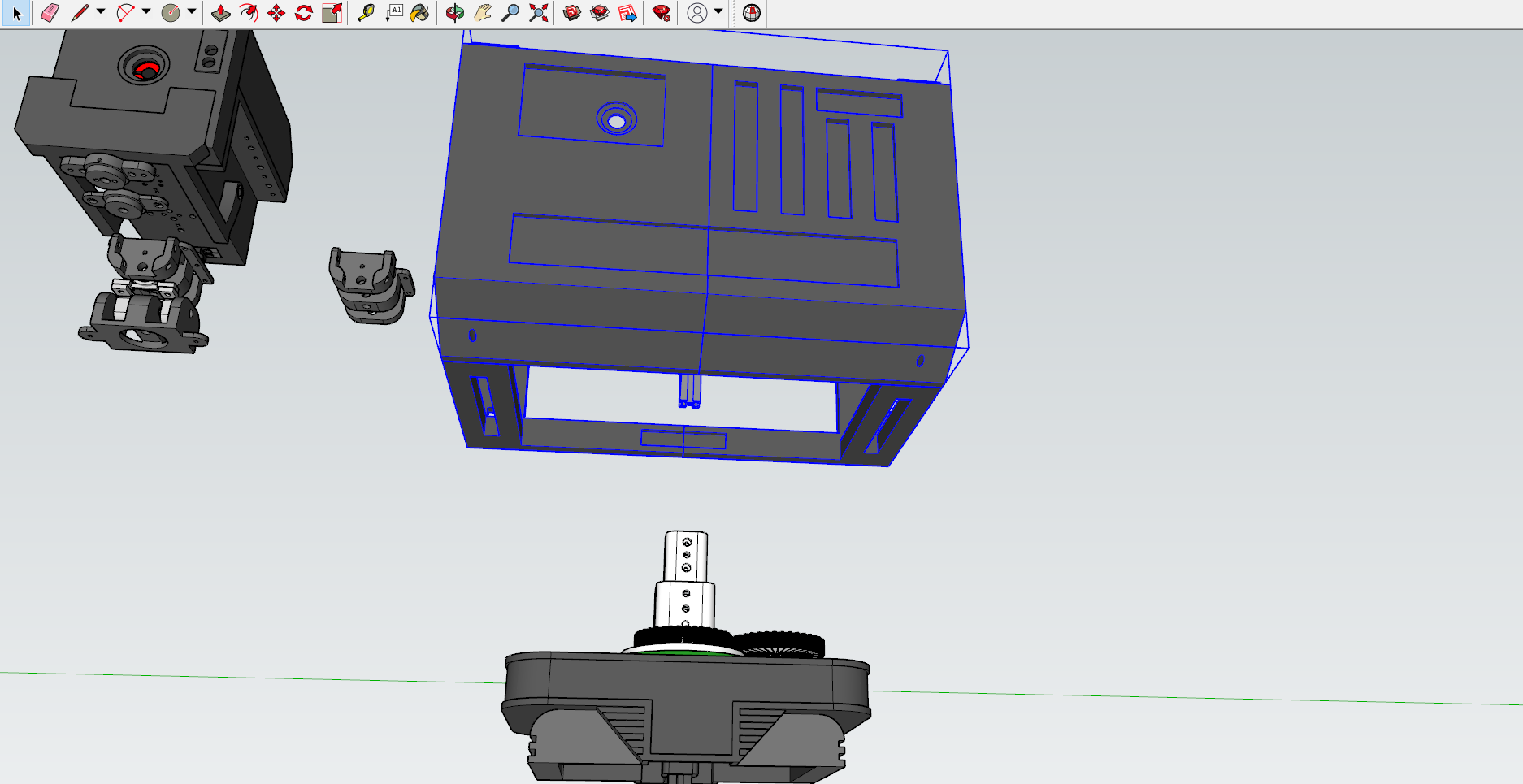
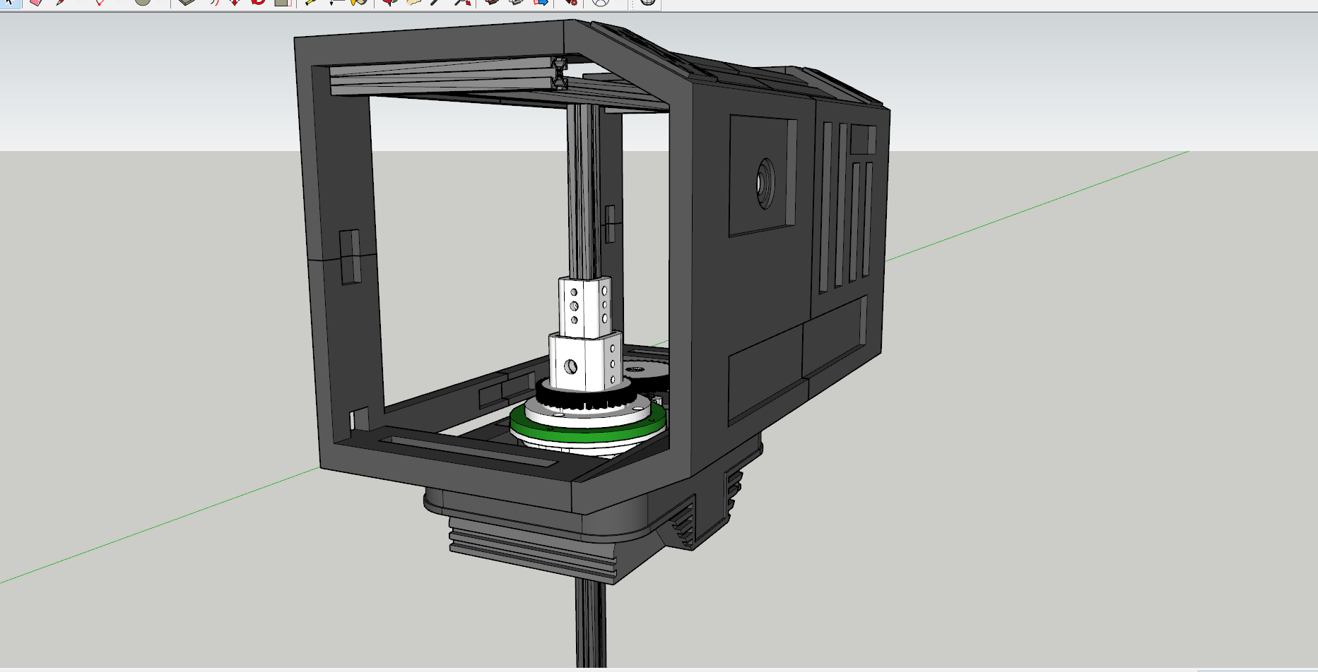
Then, assemble the torso as shown.
The Torso-2020 Bearing Mount Connector will allow you to quickly remove the upper torso (the chest) from the rest of the robot's body. Ensure you print that part strong, securely bolt it to the chest's vertical extrusion, and it should friction fit into Torso Bearing Top (V.3). This way, if you ever have to service/transport the robot, you can just pull the top half off & get to work.
Arms
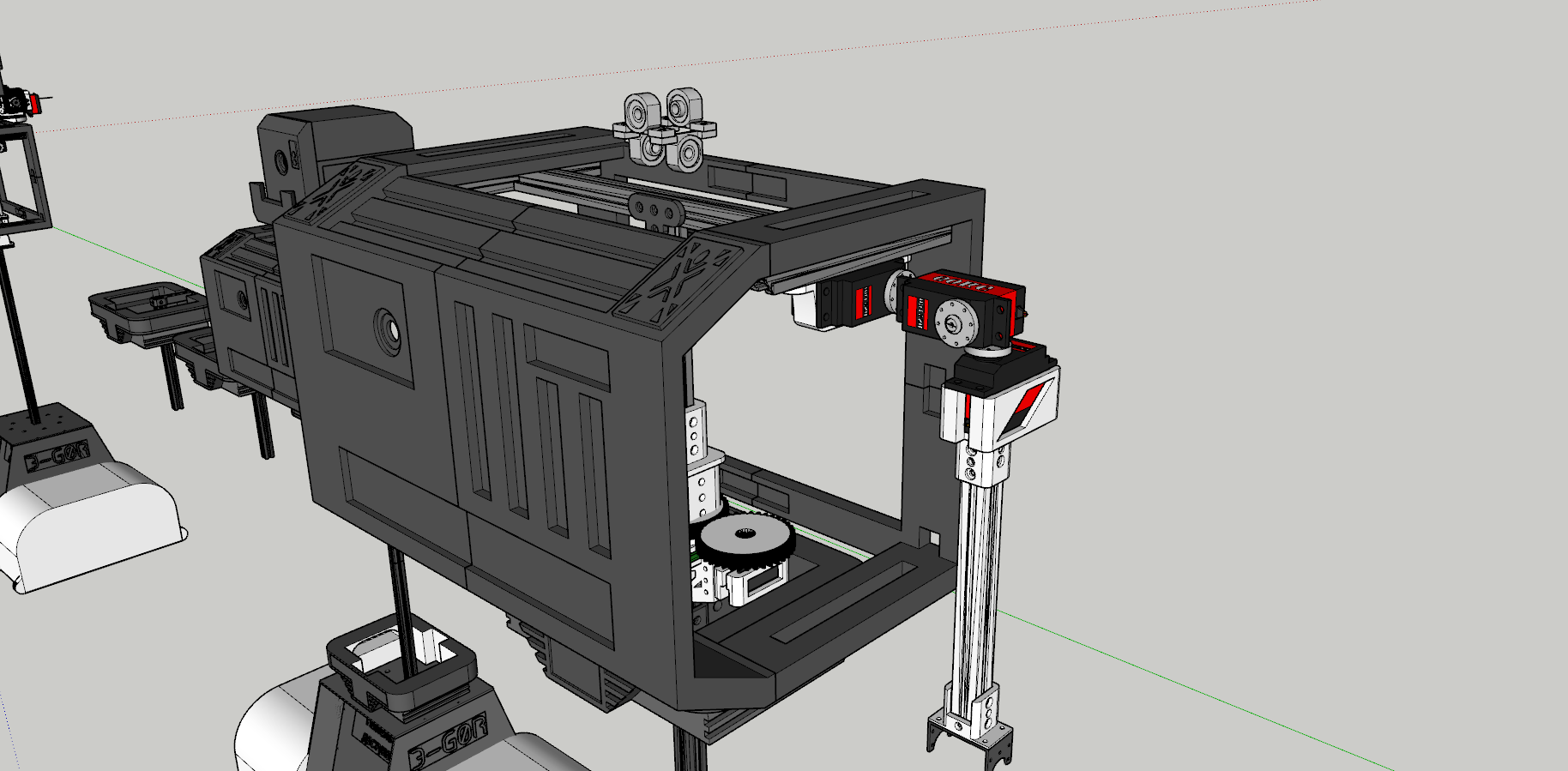.png)


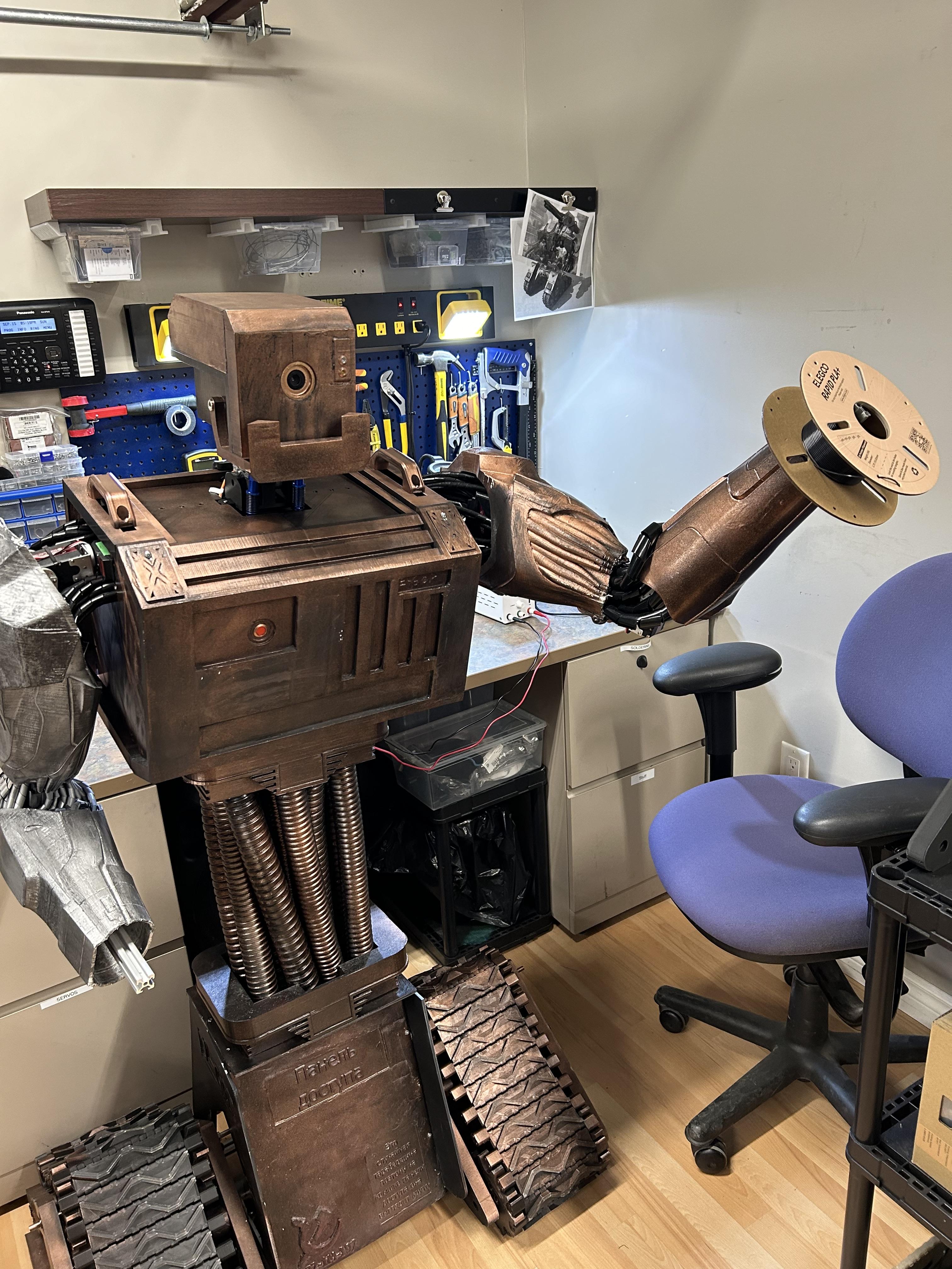


(Calibrate all servos accordingly so you don't have to keep disassembling and reassembling the arm mechanism).
Take a 150kg/cm servo and mount it to the 2020 extrusion using the Servo Shoulder Strap. Calibrate the servo to the correct max/min angle depending on which side of the arm you are doing. Take a 150kg/cm Dual Shaft servo and mount it to the Shoulder Servo (calibrate that servo as well).
Then, take the 6V 80kg/cm servo (label the wire near the connector "6V" so don't accidentally blow it with 12v thinking it's the wire for the 150kg servo) And place the 80kg servo in the Arm Rot Servo Bracket and mount the servo horn to the metal bracket of the 150kg servo.
Use a 150kg servo for the elbow and mount the according brackets. Use the Elbow 2020 Bracket to mount the servo's bracket to the extrusion (as shown in the images above).
Once you have the 2020x300mm Extrusion mounted for the arm, you can add the Bicep and Forearm. Using the Arm Frames you can slide them on the extrusion and then slide the bicep and forearms on. Once it's friction fitted, and adjusted to your liking, glue the Arm Frame to the inside of the Bicep/Forearm to prevent the Bicep/Forearm from accidentally falling/sliding off. Secure the Arm Frames to the extrusion using M3x8 screws and T-nuts.
(Refer to images above)
I calibrated all the servo's ahead of time, here are my values (Of course these are dependent on the way your servo is installed/facing:
R-Arm:
Shoulder (Up/Down): Set to 0 degrees Range: 0-90 <100 degrees
Shoulder (Left/Right): Set to 270 degrees Range: 270–90 degrees
Shoulder (Rotator): Set to 0/180 degrees (this depends on which way the servo faces) (This is the 6V servo)
Elbow: Set to 90 degrees
L-Arm:
Shoulder (Up/Down): Set to 270 degrees
Shoulder (Left/Right): Set to 0 degrees
Shoulder (Rotator): Set to 0/180 degrees (this depends on which way the servo faces) (This is the 6V servo)
Elbow: Set to 90 degrees
Wiring
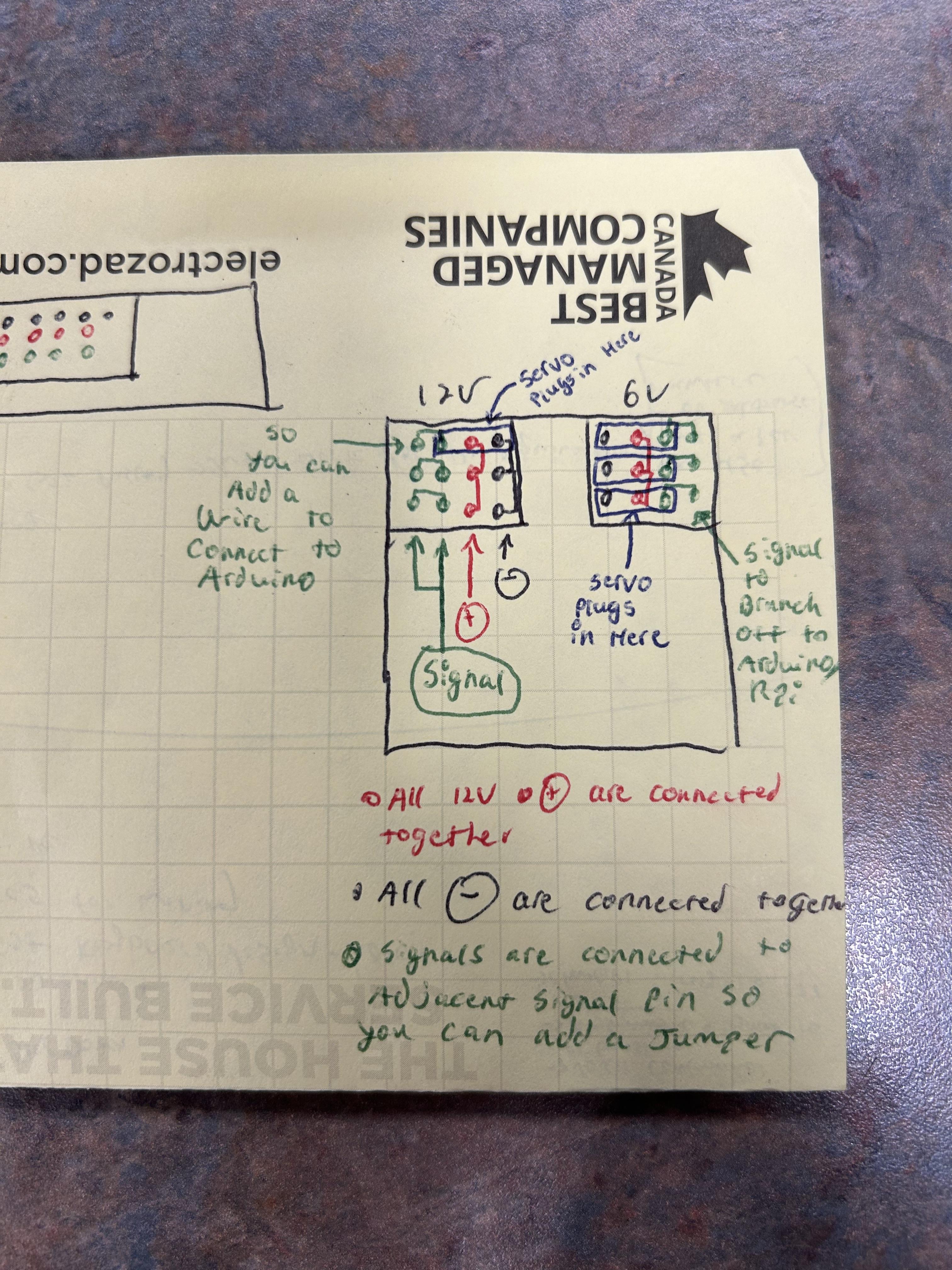


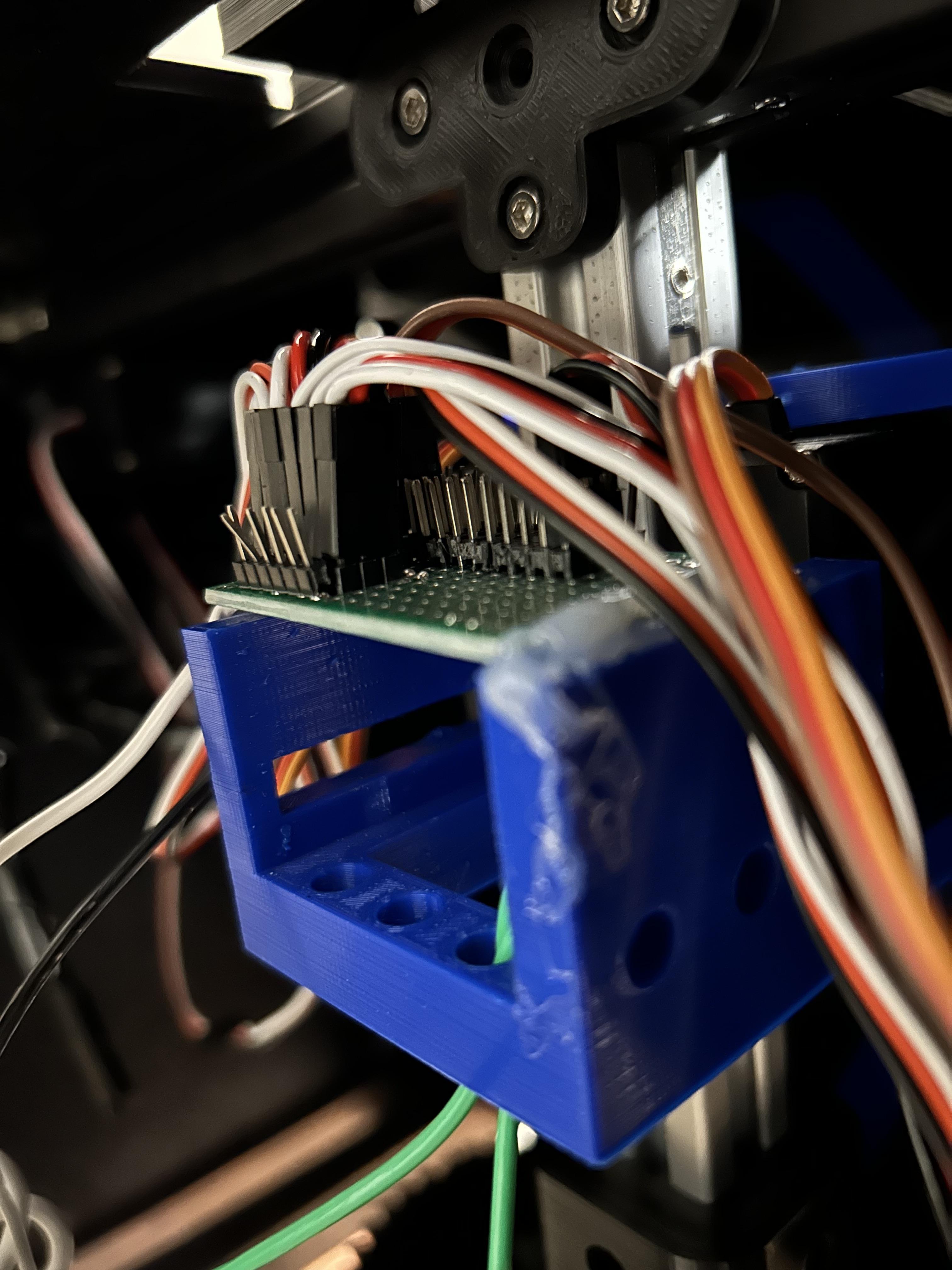


To control the servos, they must first be hooked up. To achieve this, I made a custom board to make the connections easier to manage using a PCB board, some male header pins, and some scrap 18awg wire I had.
Take your PCB board and designate 2 halves. One half will be for the 12V servos and the other half will be for the 6V servos. Make a row of 4 header pins on both the 12V/6V side. The 4 header pins will be: +, -, signal & signal (refer to the sketch above). Do this for all the 12v and 6v servos you have so they all have a spot to plug into (I recommended adding extra rows/spots for lights & any other add-ons that might take 12/6v).
Once all the rows were soldered in place, I took a 18awg whip and used it to make continuity for the +12V row. I then did the same for the negatives, and the +6V.
Once that is complete, use a multimeter, to test continuity across the rows to ensure there are no shorts between the pins.
Now you can attach jumper wires to each servo signal pin and bring them to the microcontroller of your choice.
Connect your power.
I connected 12V to 12V power & 6V to 6V power (I used a 12V-6V 10A transformer to get 6v)
Don't forget to connect the microcontroller to the common gnd or else your servo's won't work properly.
Now you can program your robot to move using the software of your choice.
I'm currently trying to make it somewhat autonomous using Python, OpenCV, & Arduino (I'll release the code once I get it working). But for now you can make pre-programmed movements or make it remote controlled.
I personally like to use Pololu Maestro's servo control board (since I have one) to create pre-programmed movements for my robots. But there is a new software that uses Arduino to make smooth pre-programmed routines called Bottango. (I would check that out if you want to get started on brining your robot to life)