Dudeneys Dissection
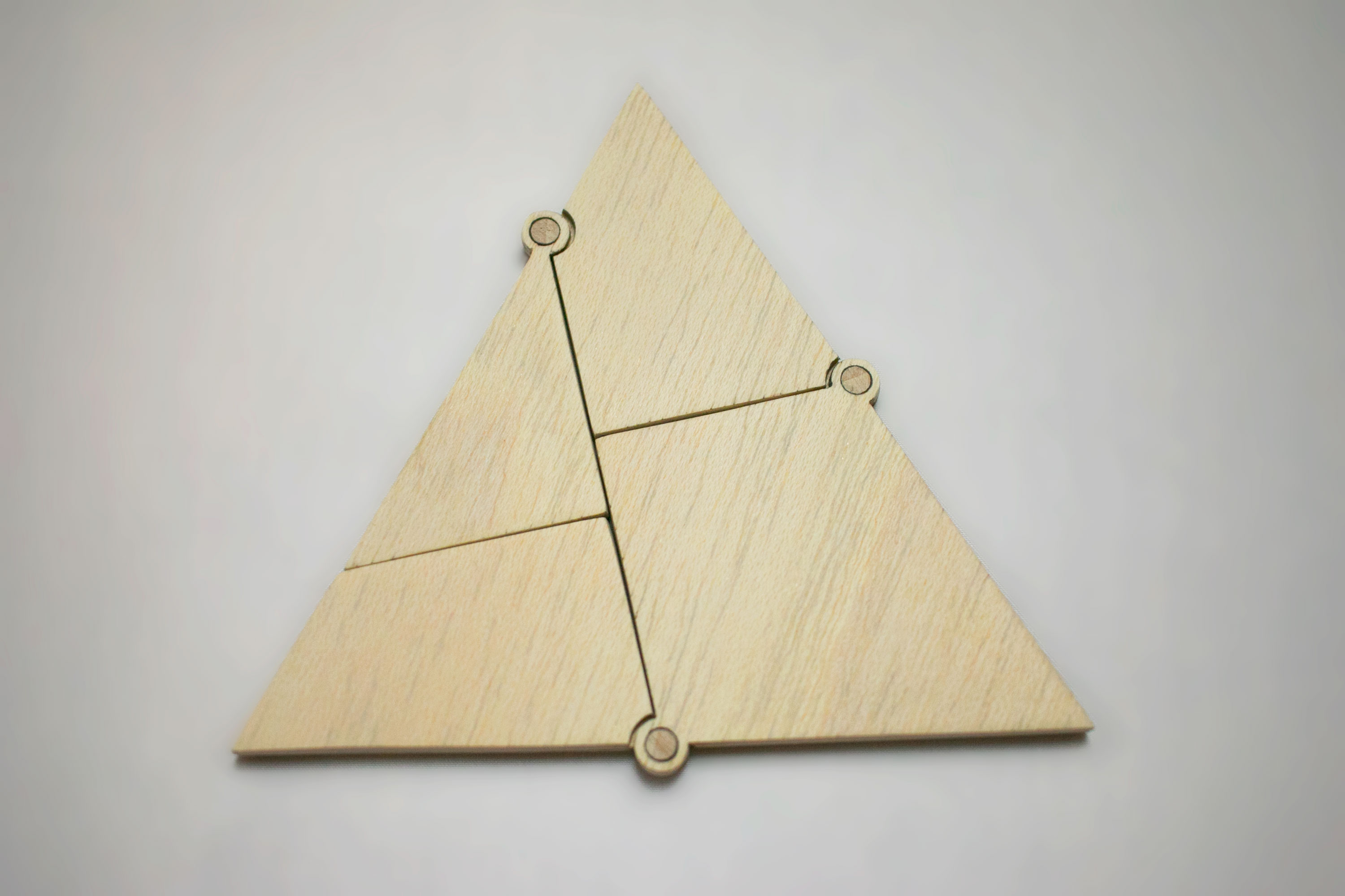
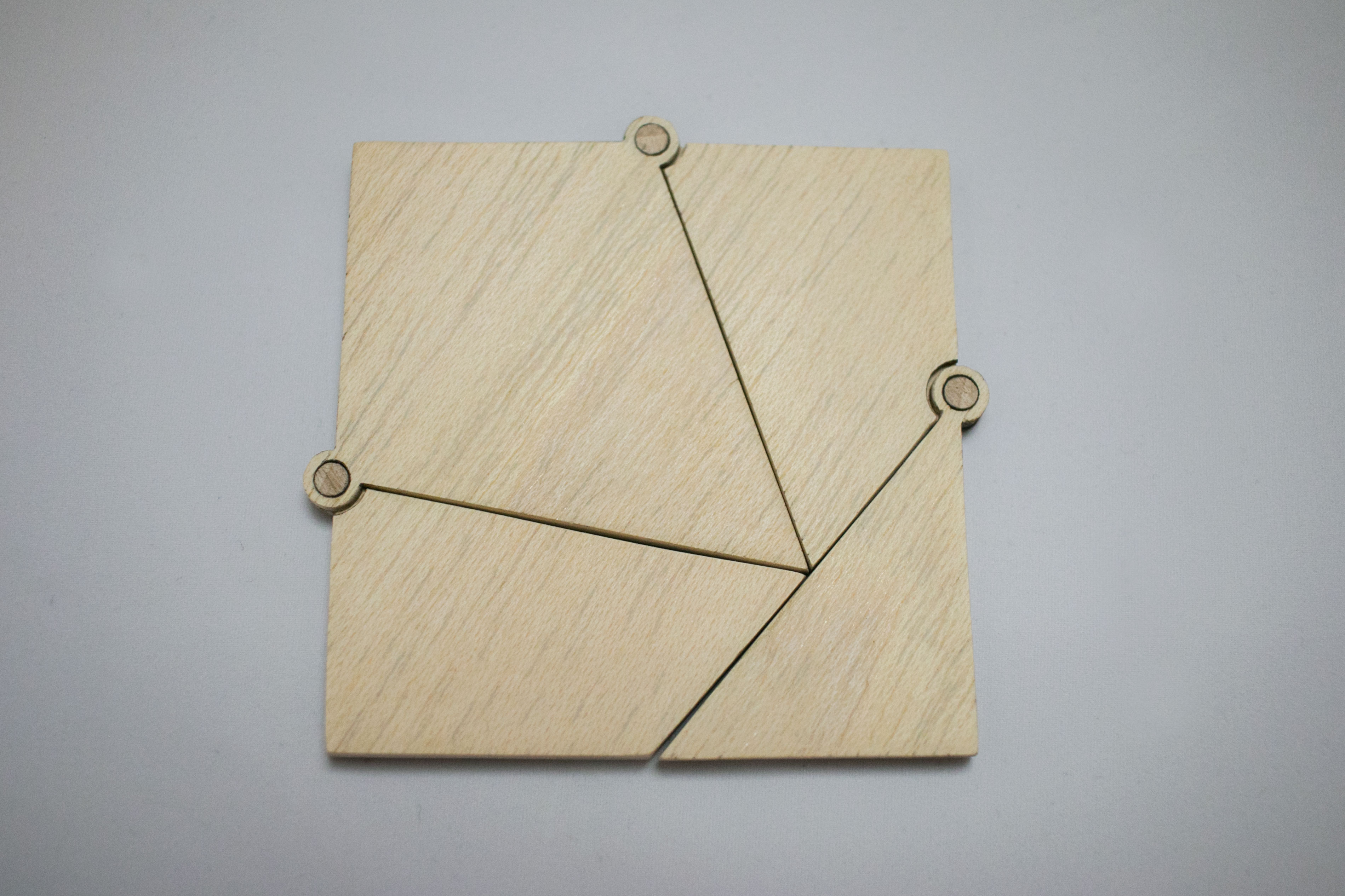
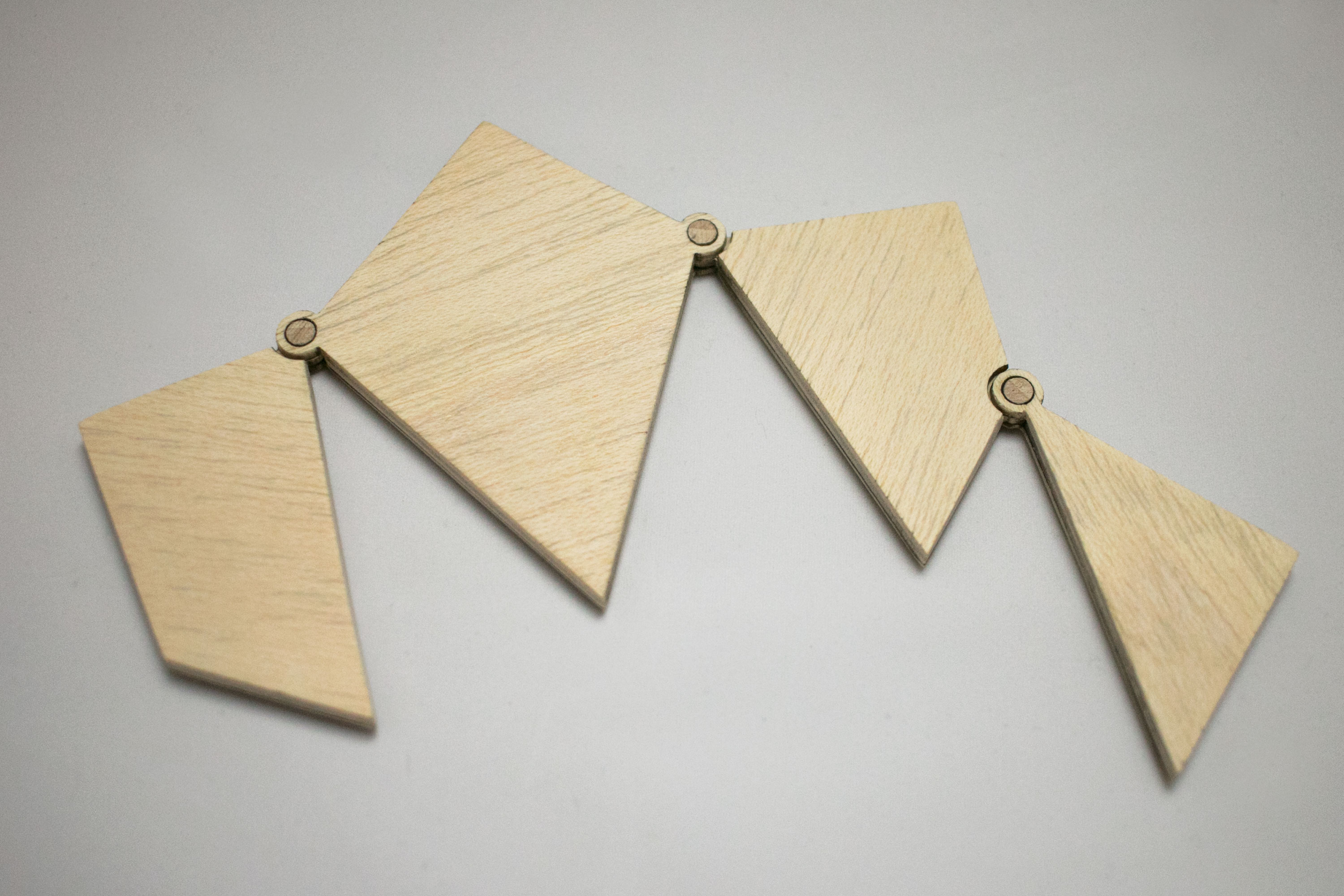
Ever since I had seen this puzzle I wanted to build my own version. I did some research and found out that there are many different hinged dissections, in which all of the pieces are connected into a chain that allows one figure to be rearranged to another, but I decided that the one I had seen was the coolest.
Henry Dudeney popularised this type of puzzles in 1907 by publishing his book "The Canterbury Puzzles".
It also exists in a lot of different variations, for example as a packaging box.
Designing the Puzzle
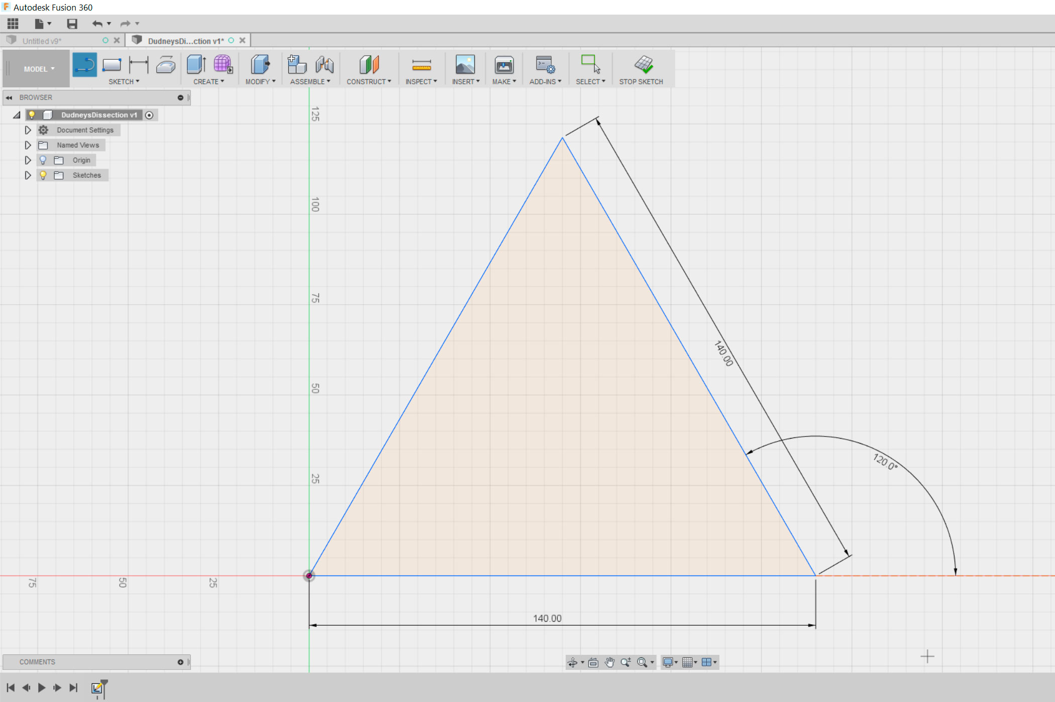
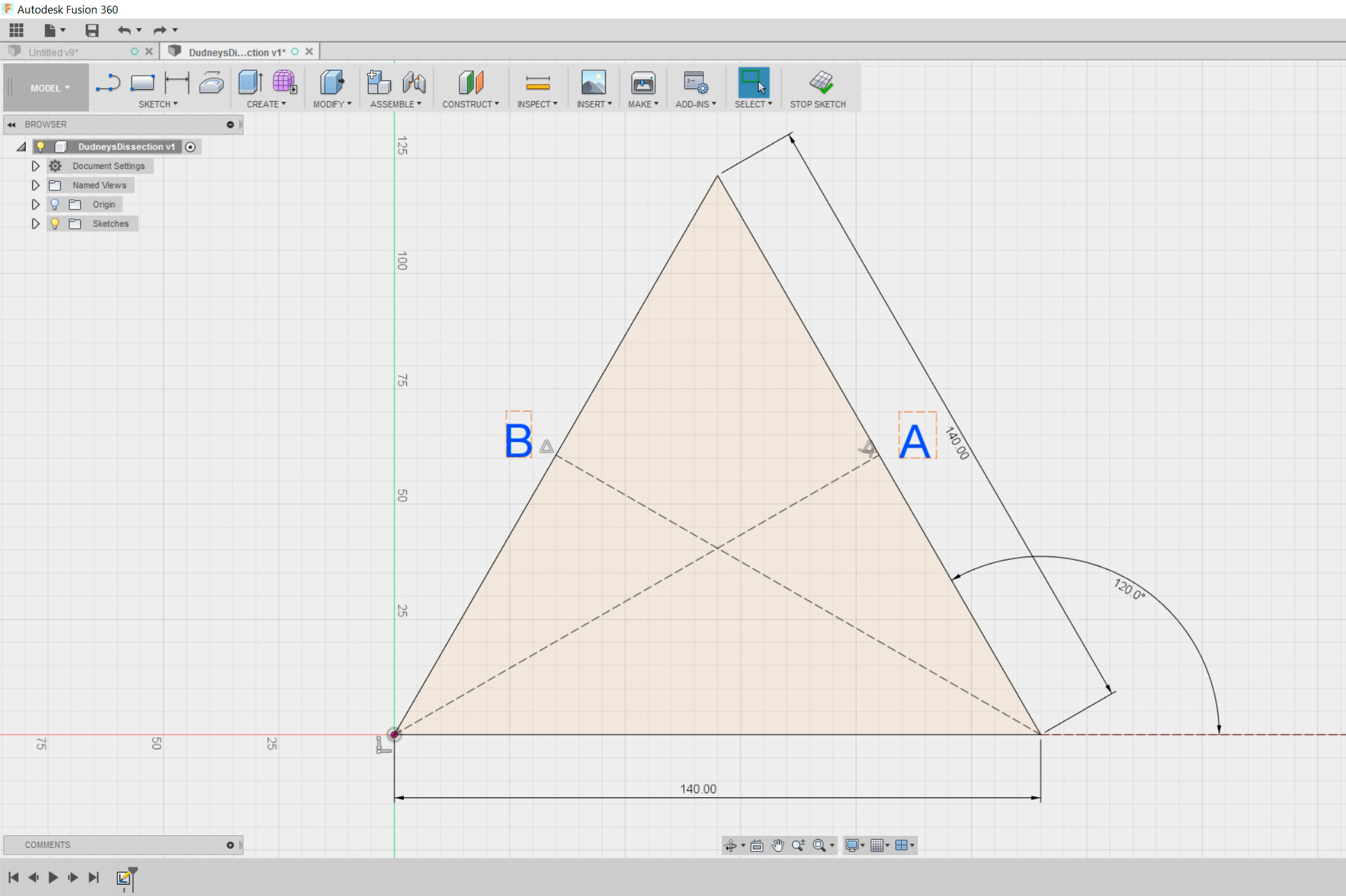
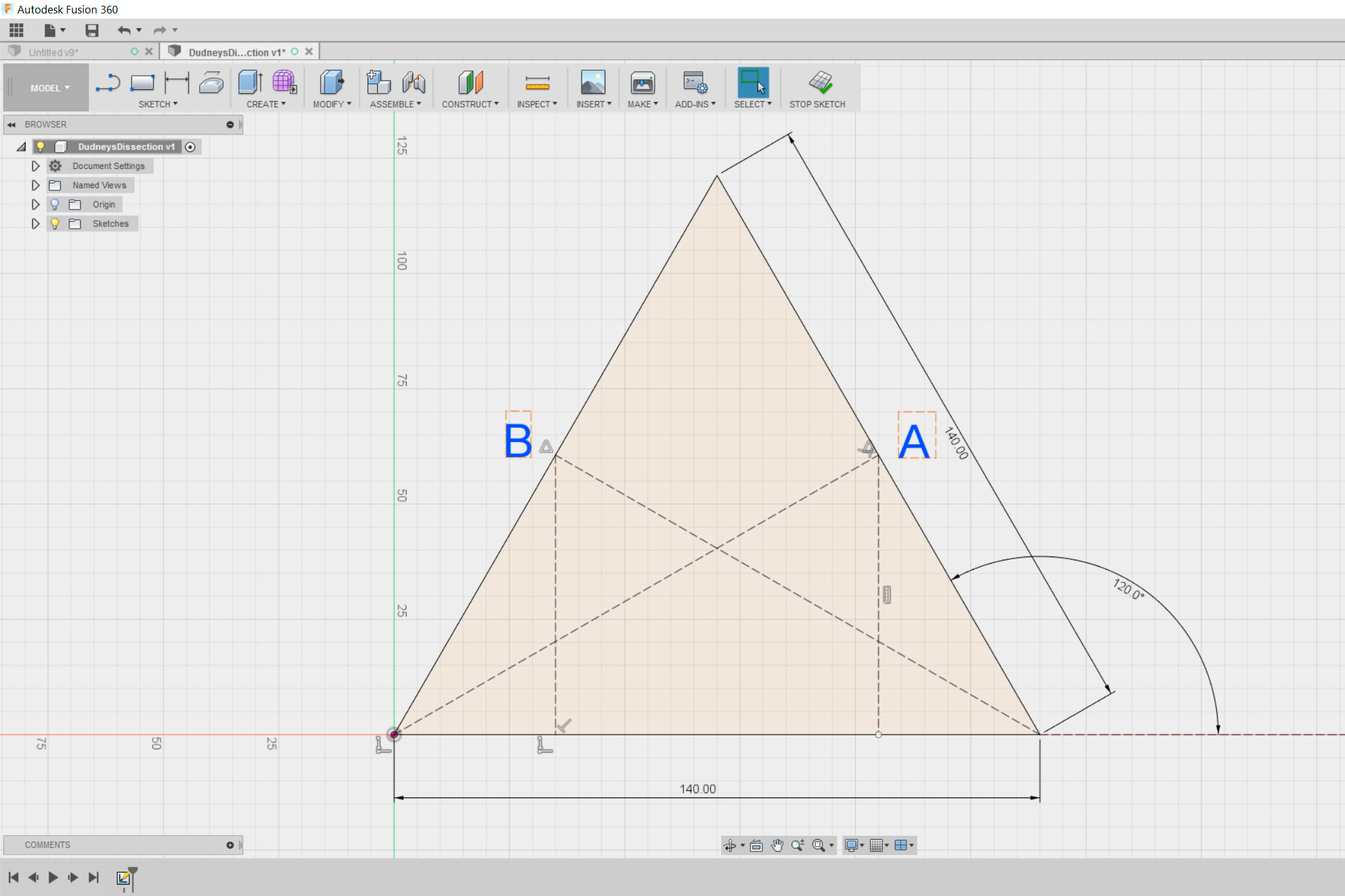
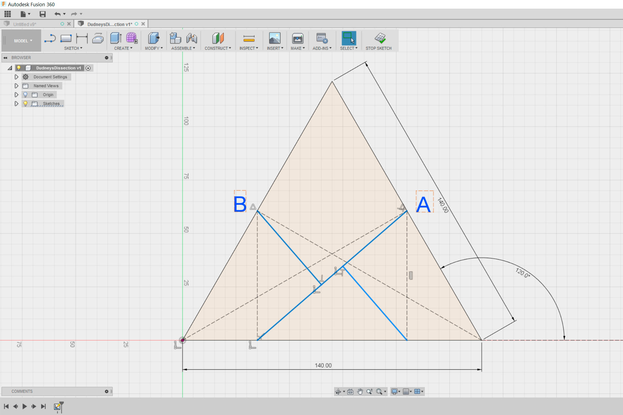
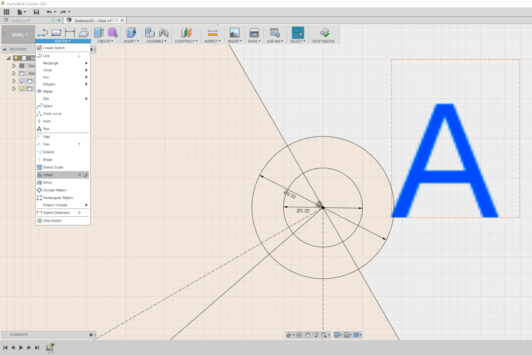
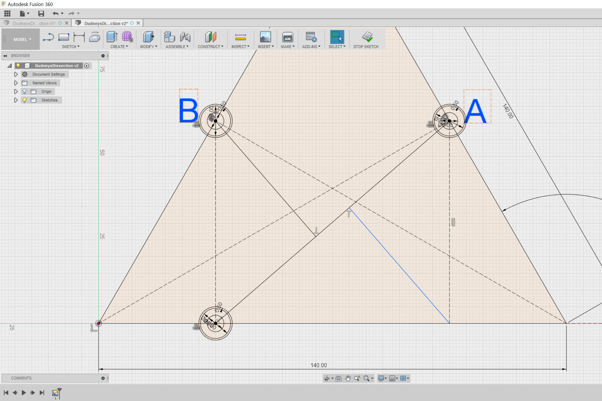
I designed the dissection in Fusion 360 and am quickly showing you how I did it in the next two steps.
Start by drawing an equilateral triangle. As you can see in the pictures I made mine 14 cm long. Don't make it too small since it might break.
Next draw two lines from the two bottom corners to the middle of the opposite site, as shown in the second picture. Then draw two perpendicular lines to the points I named "A" and "B" starting from the line on the bottom. By selecting a line and hitting "X" you can turn it into a construction line.
Now connect the bottom of the left perpendicular line to point "A" and draw two more perpendicular lines to the line you just drew, as shown in the fourth picture.
All that is left to do it to draw the hinges, as shown in the picture. As you can see I used a small offset, to make sure that the pieces move smoothly.
Extrusion
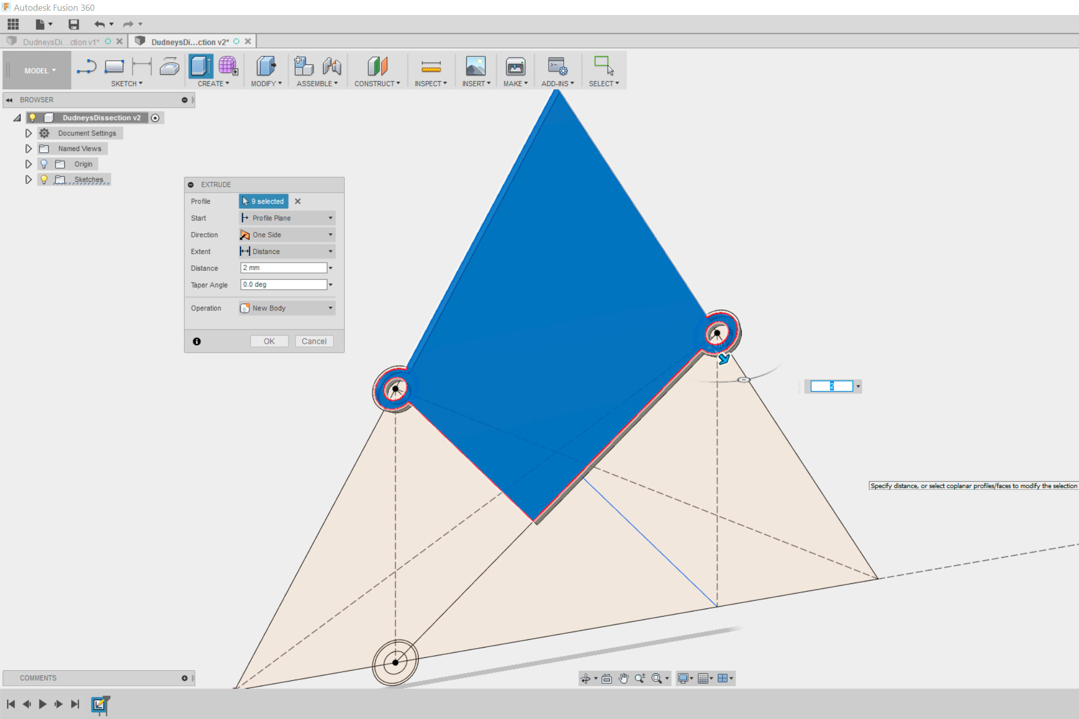
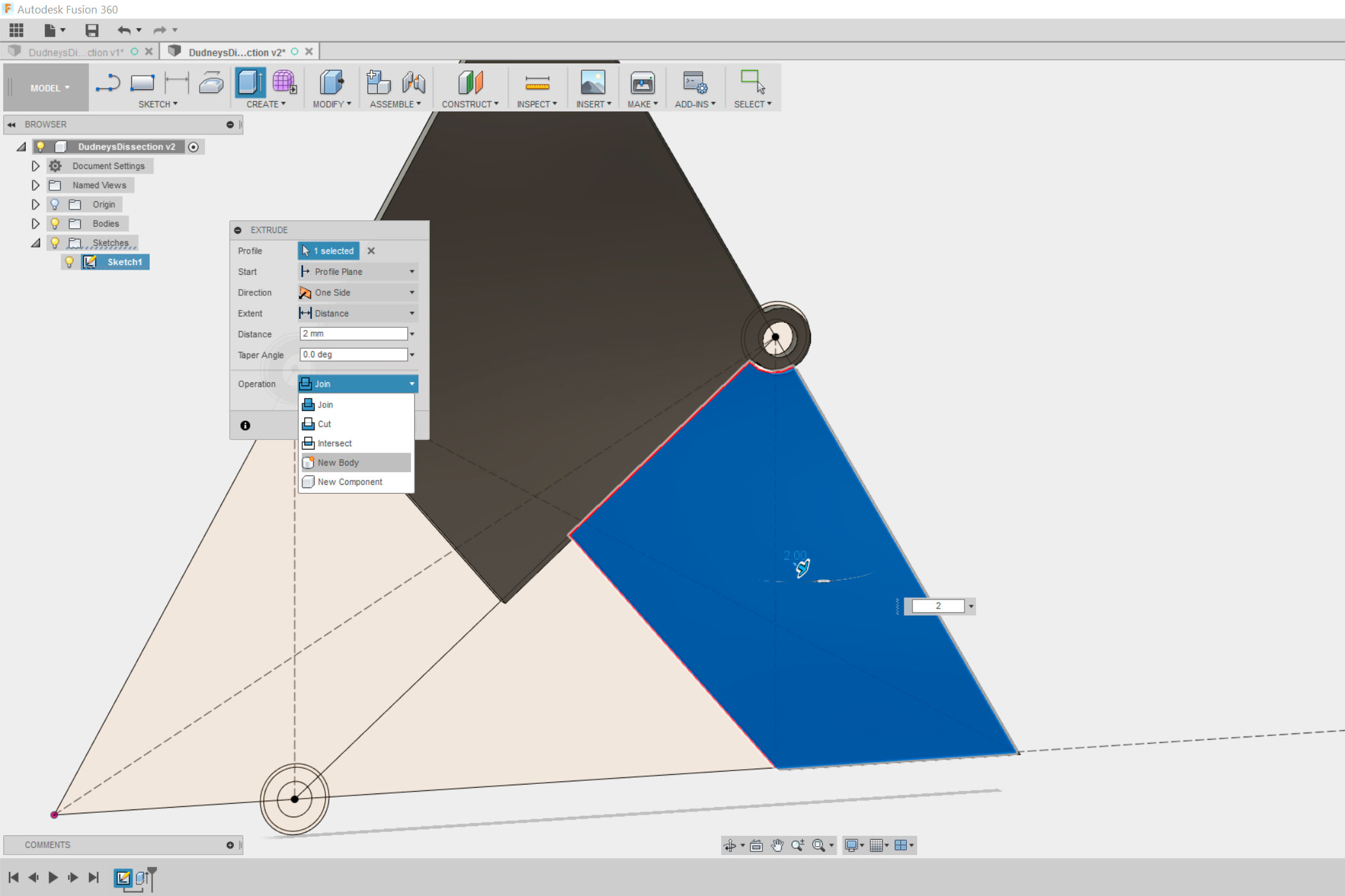
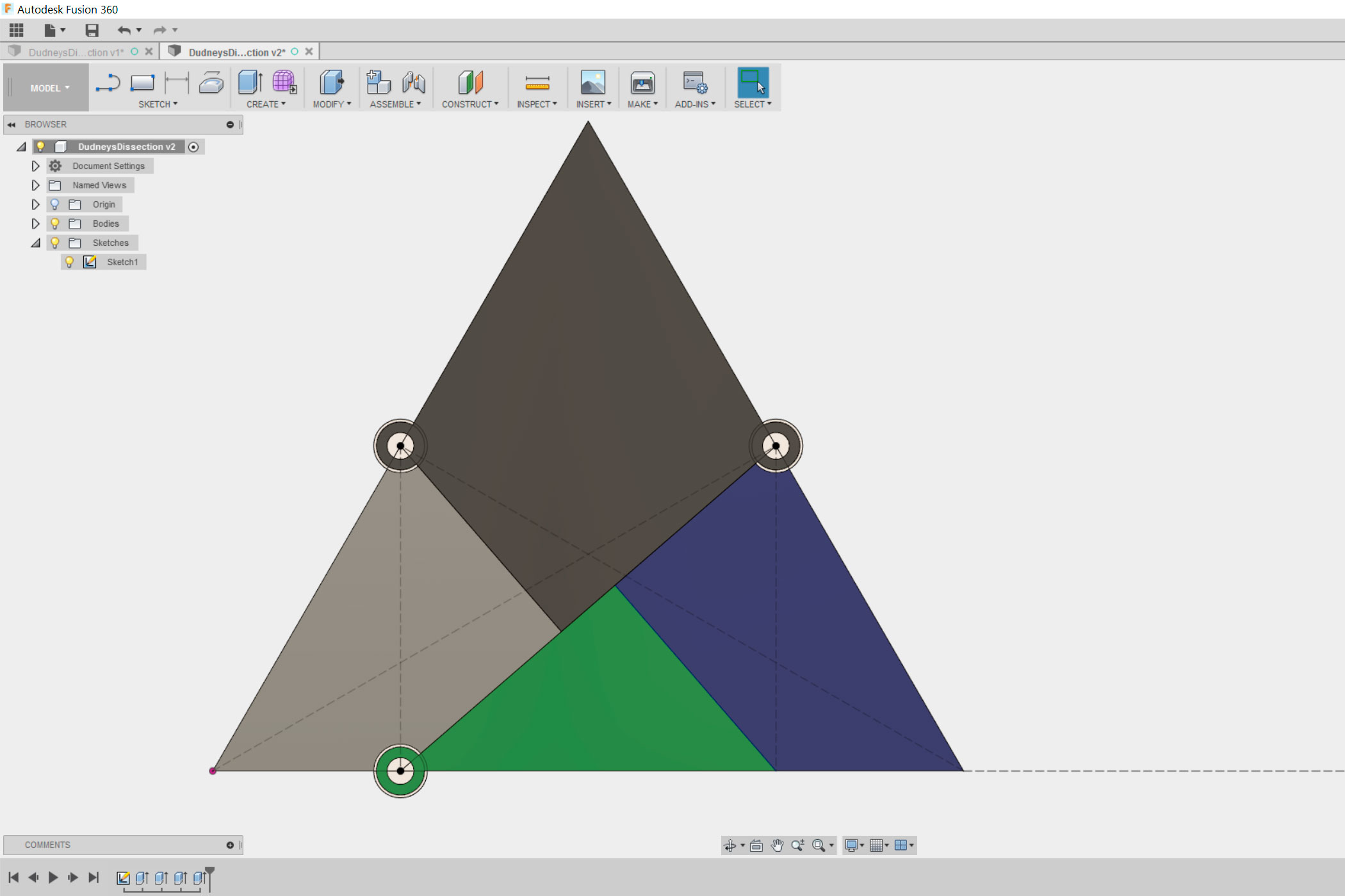
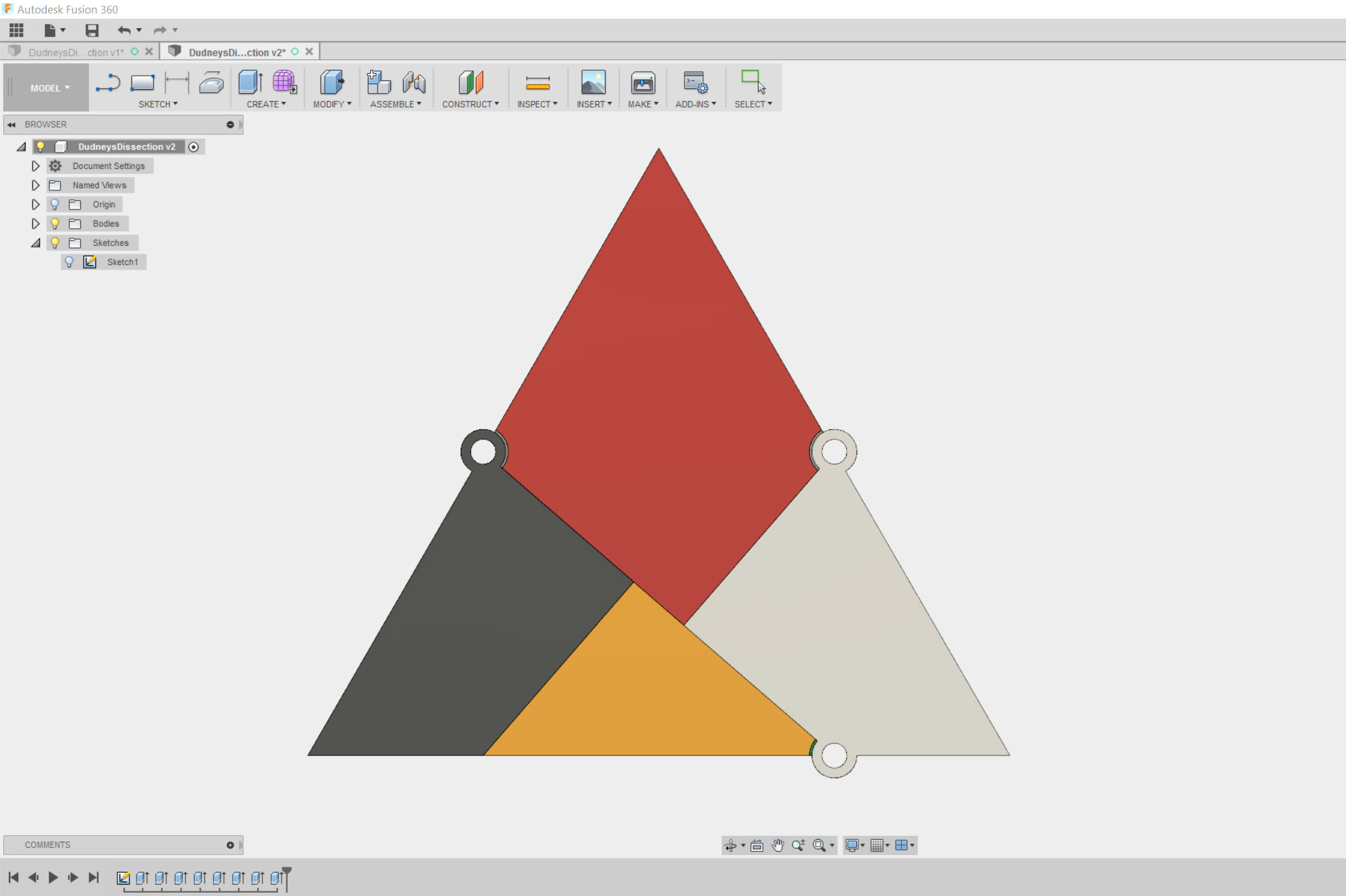
Next you will have to extrude the pieces, as shown in the pictures. Make sure to select "New Body" under "Operation" otherwise all the pieces will melt together.
Once you are done with the first site turn the piece and proceed to the other site, as shown in the pictures.
Making a 2D Drawing
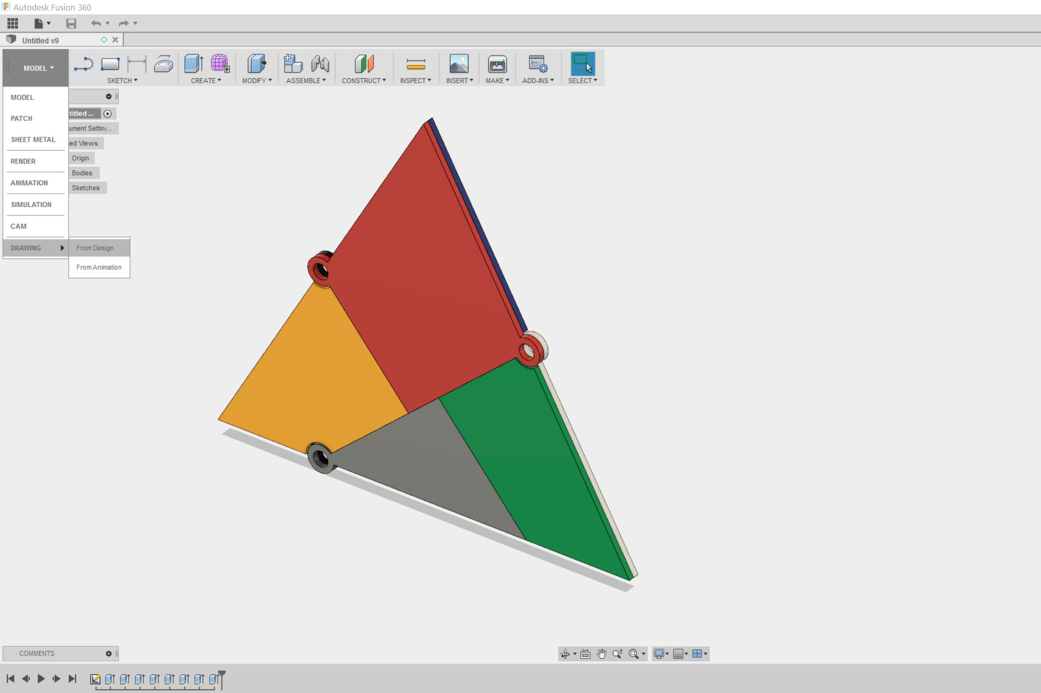
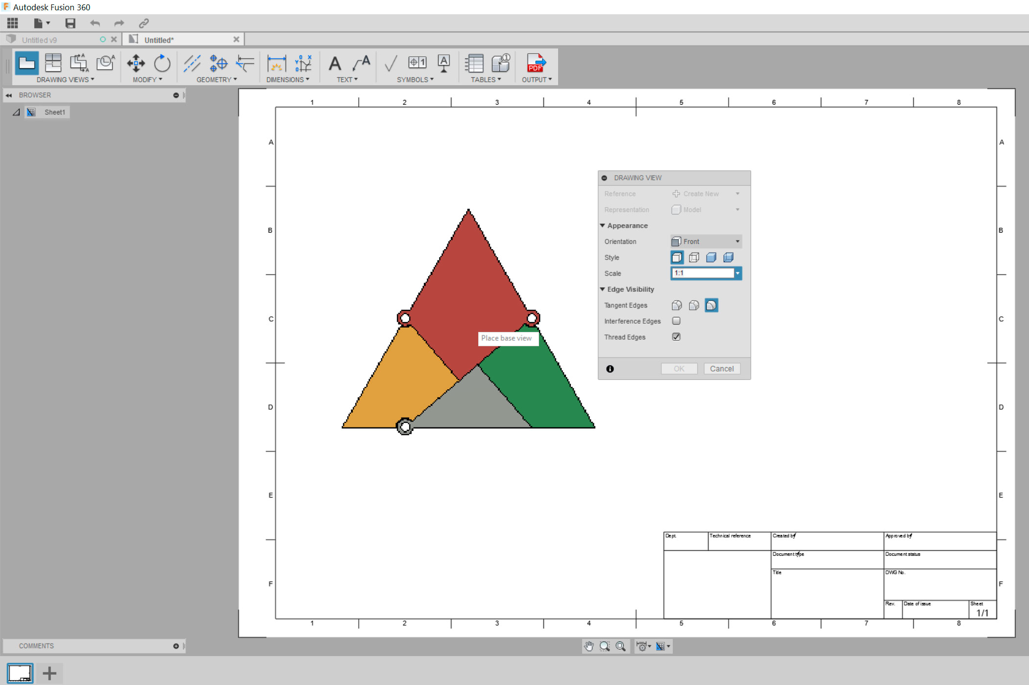
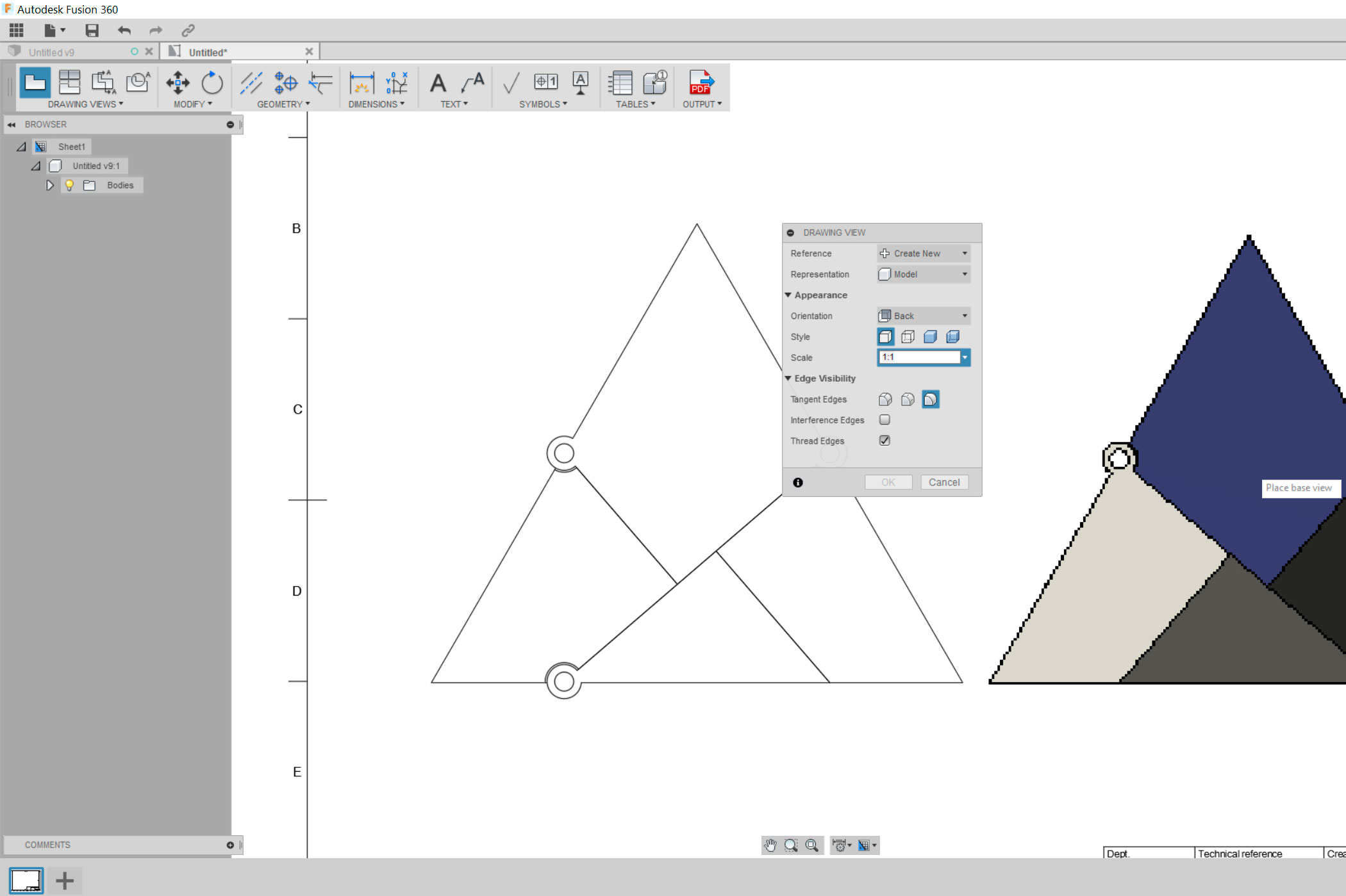
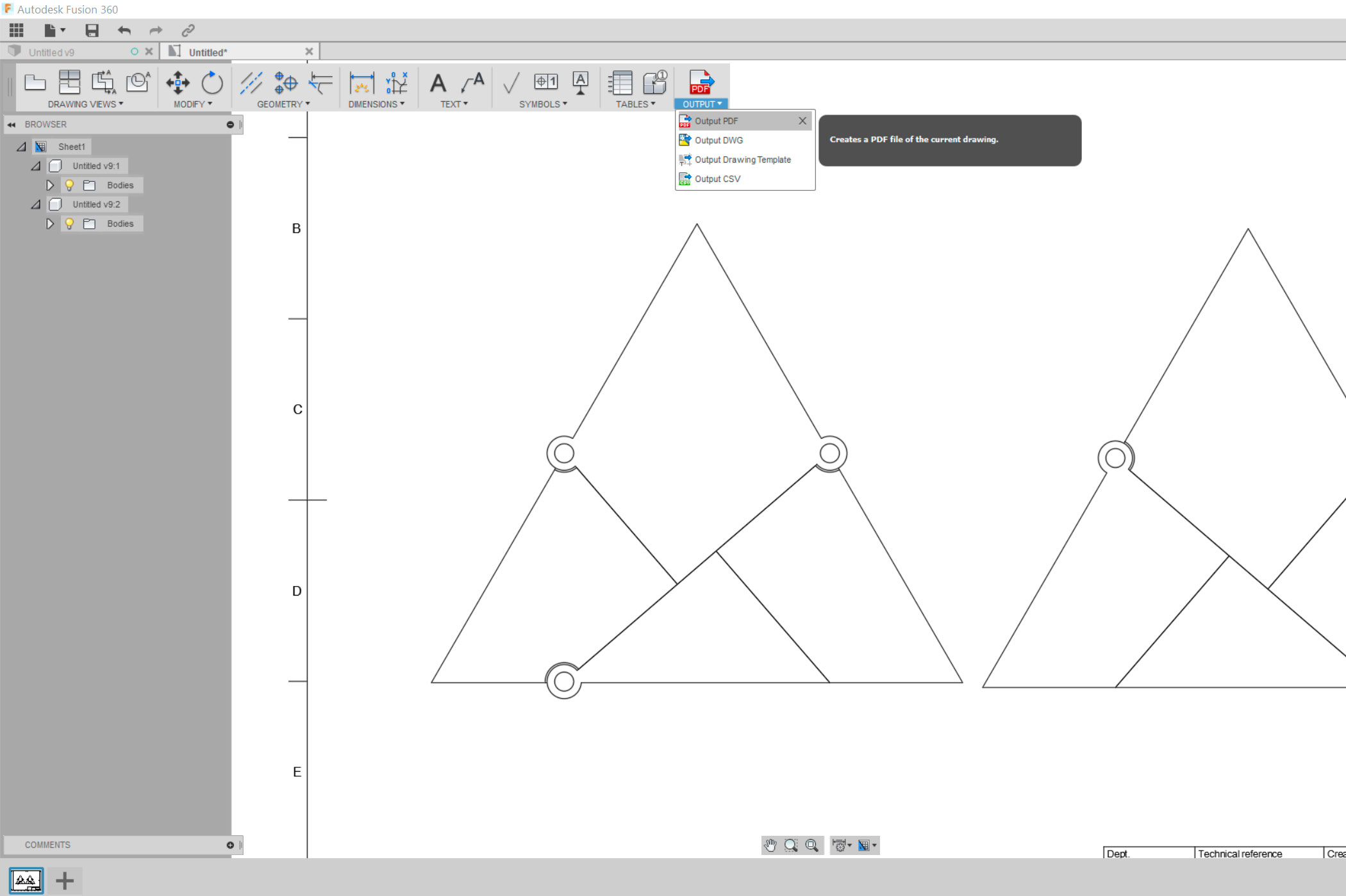
Once you are done, select "Drawing" instead of "Model". Make sure to set the scale to 1:1. You will have to export the front and the back.
Export the drawing as a pdf file.
Inkscape
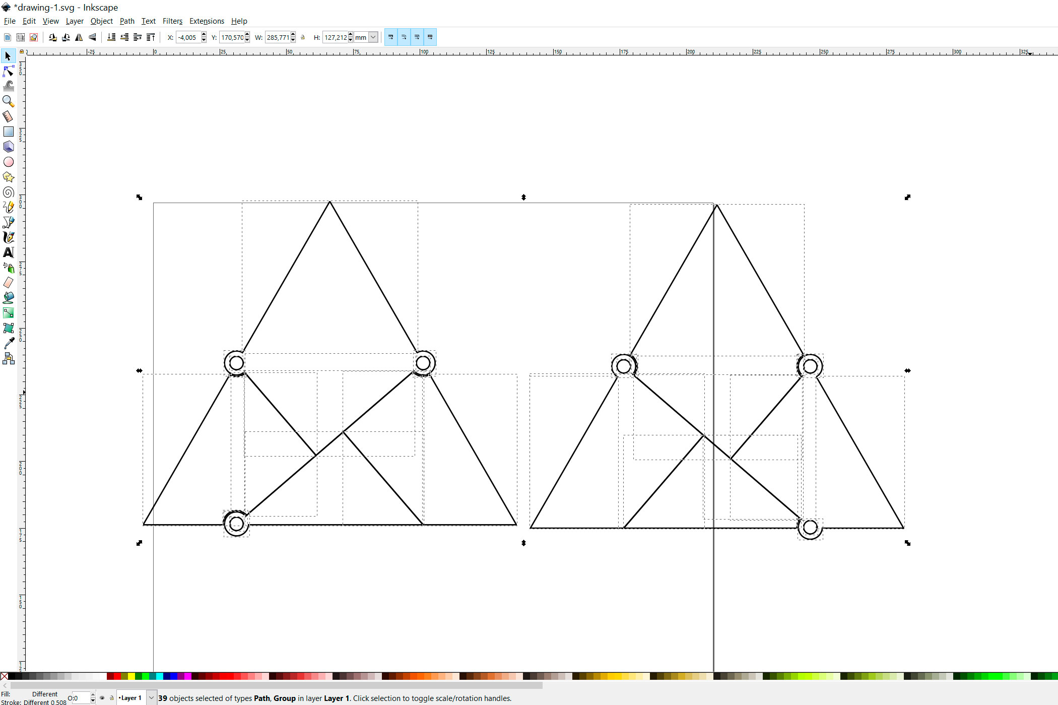
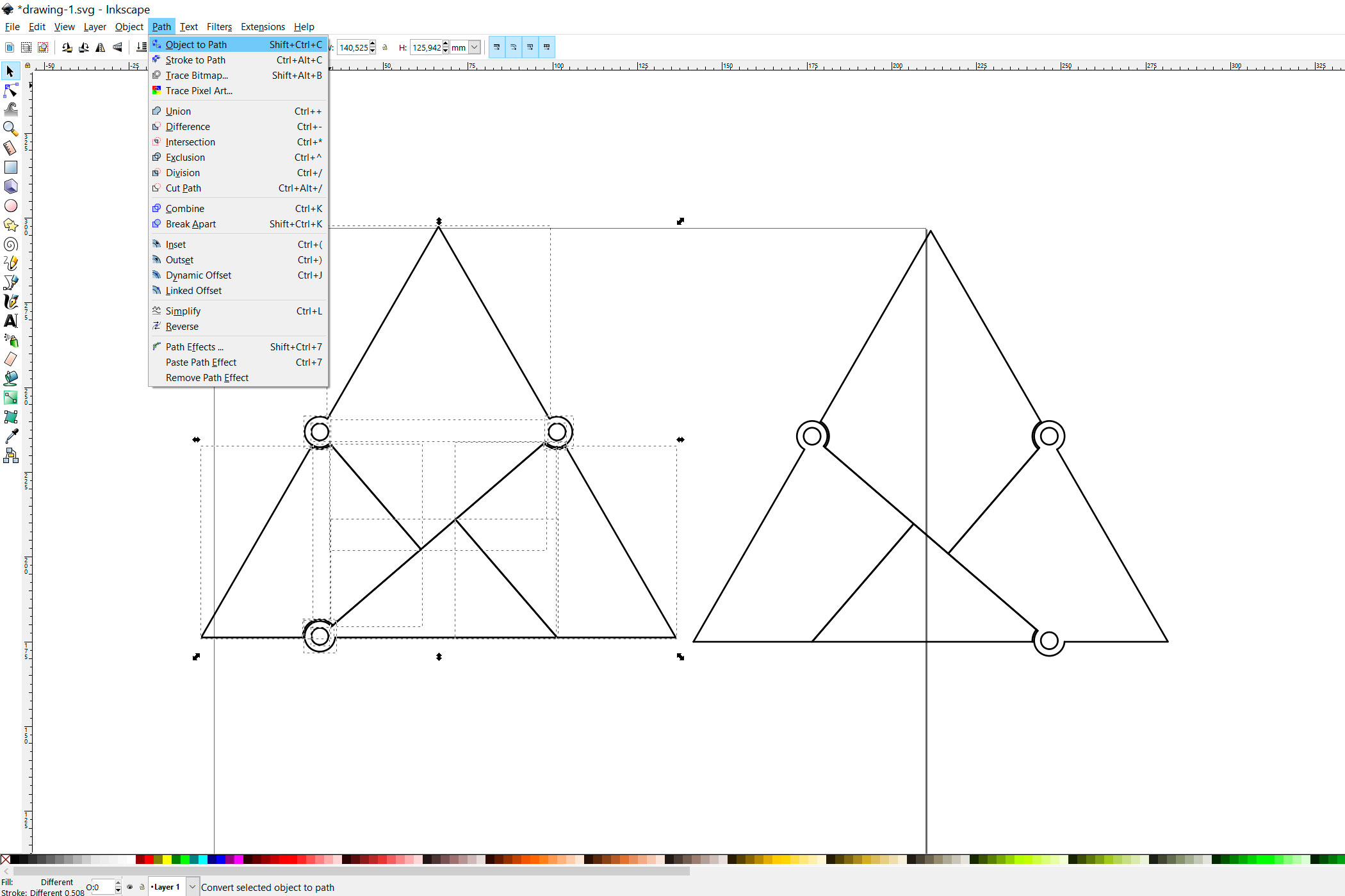
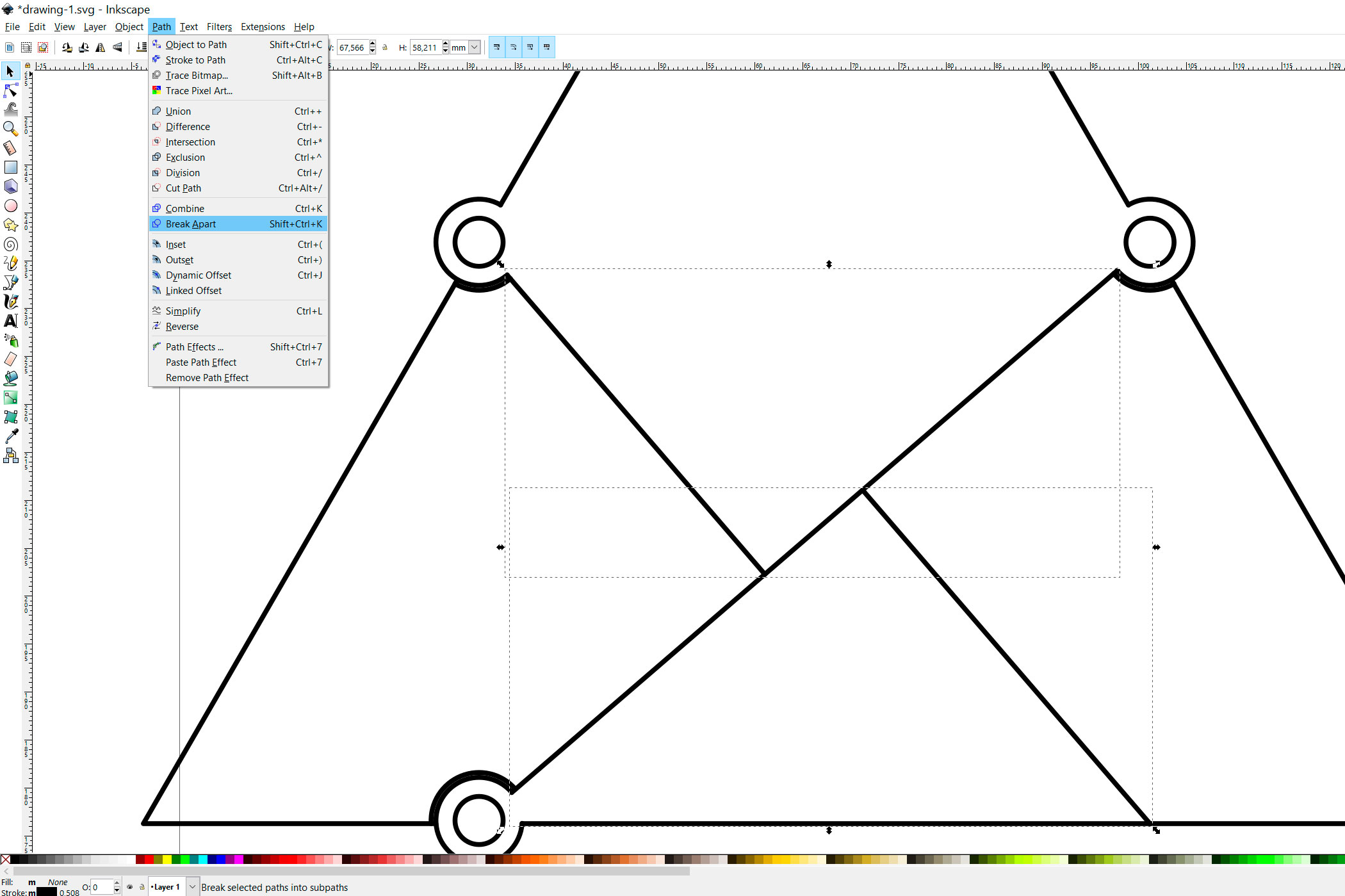
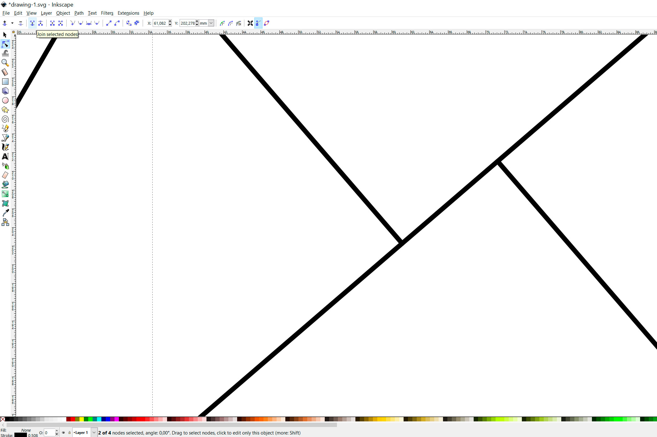
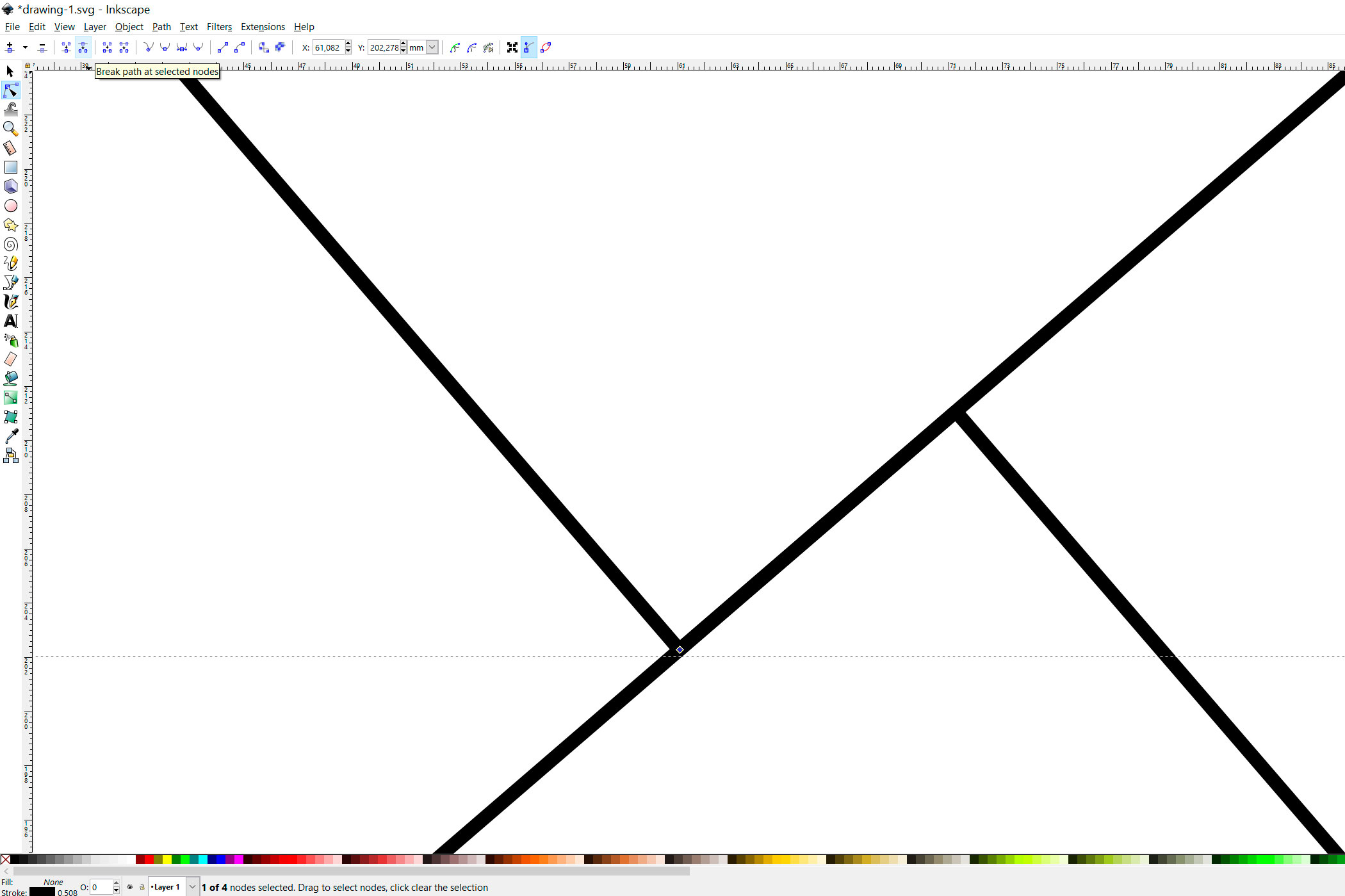
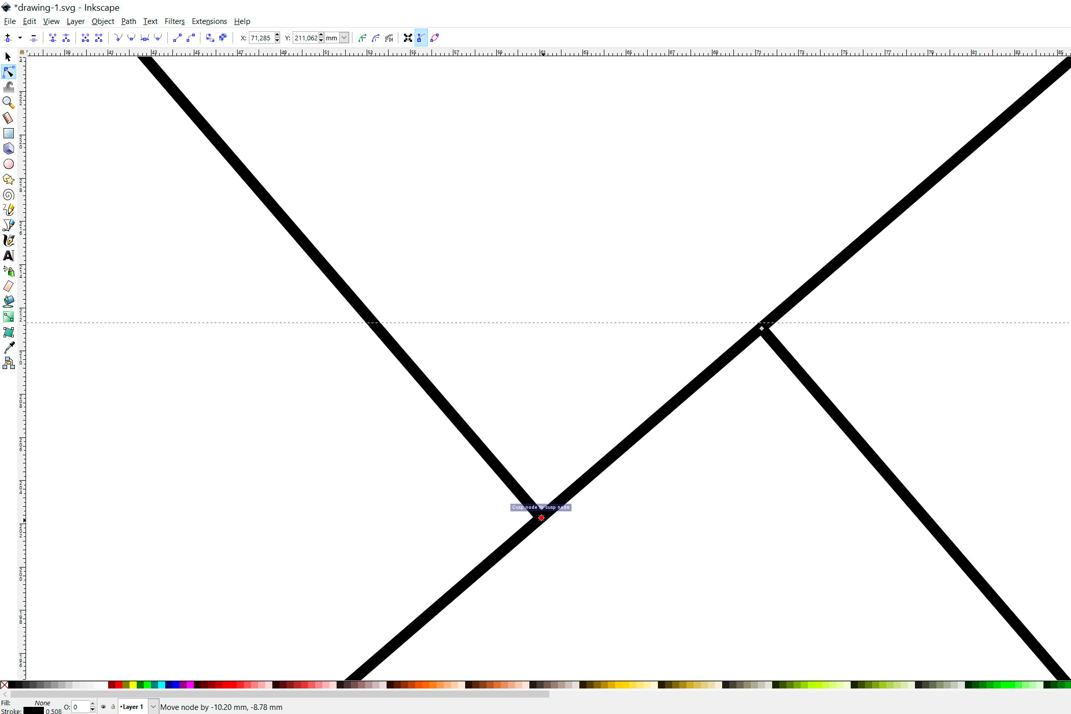
In this step I am going to show you how I optimized the files for 3D printing. There are a few duplicate lines, you can just leave them, but it would result in your laser cutter cutting those lines twice.
I used inkscape for the editing
Start by ungrouping the objects. Afterwards turn the objects into paths and remove all the lines that are double. There is a small piece that can't be fixed by deleting lines. This can easily be fixed. Select the node in the corner and break the path by clicking on the icon as shown in the pictures. Now you can move one of the nodes of the middle line to the other. Break the pieces apart and reconnect the middle line by clicking on the "Join selected nodes" icon.
I have uploaded my finished file to this step, should you not want to go through the whole process.
Downloads
Preparation
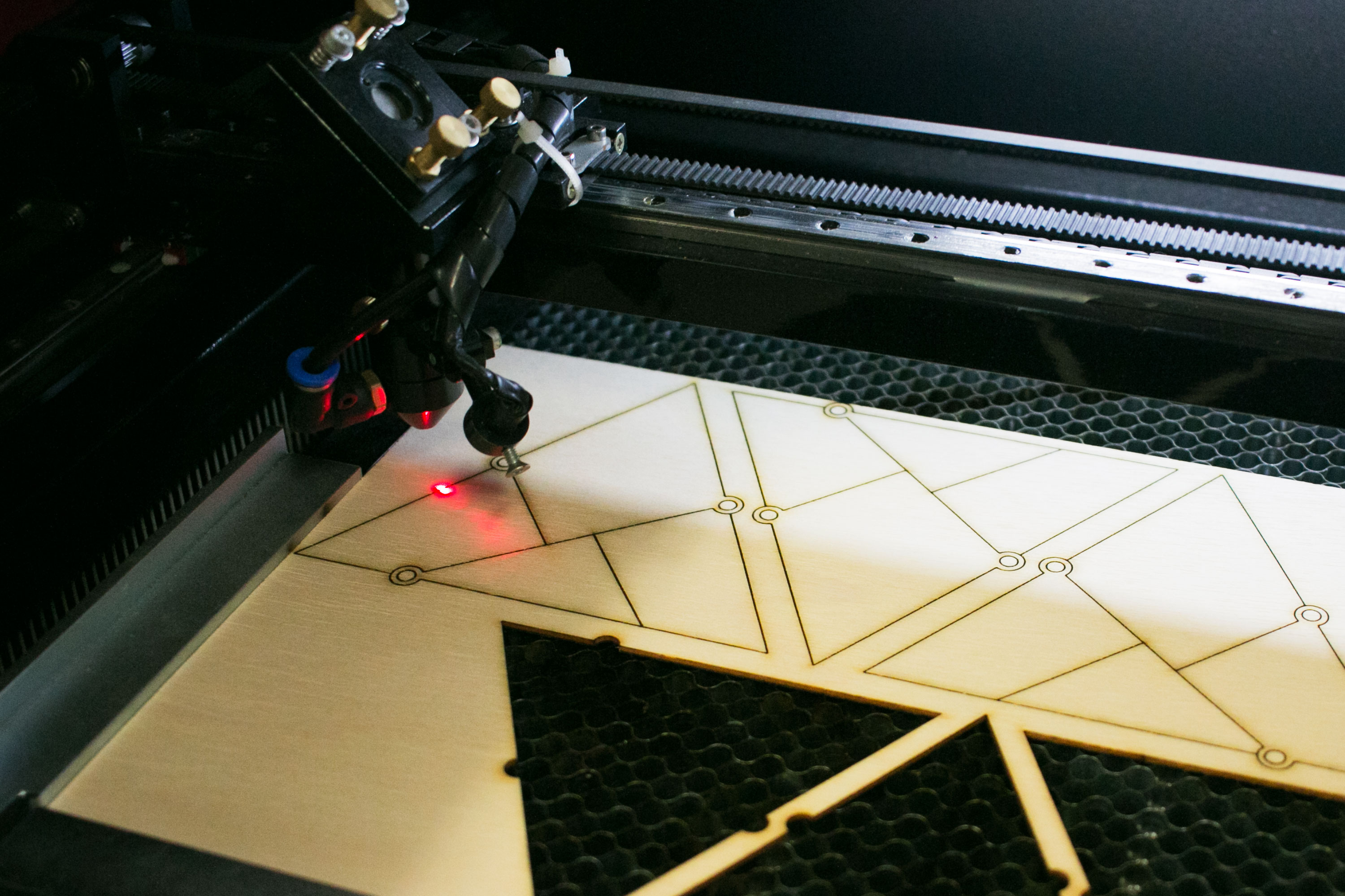
It is up to you, how thick the wood is you are going to use. I used 2 mm plywood.
Simply laser cut the pieces. You will have to cut one twice, because it will form the top and the bottom.
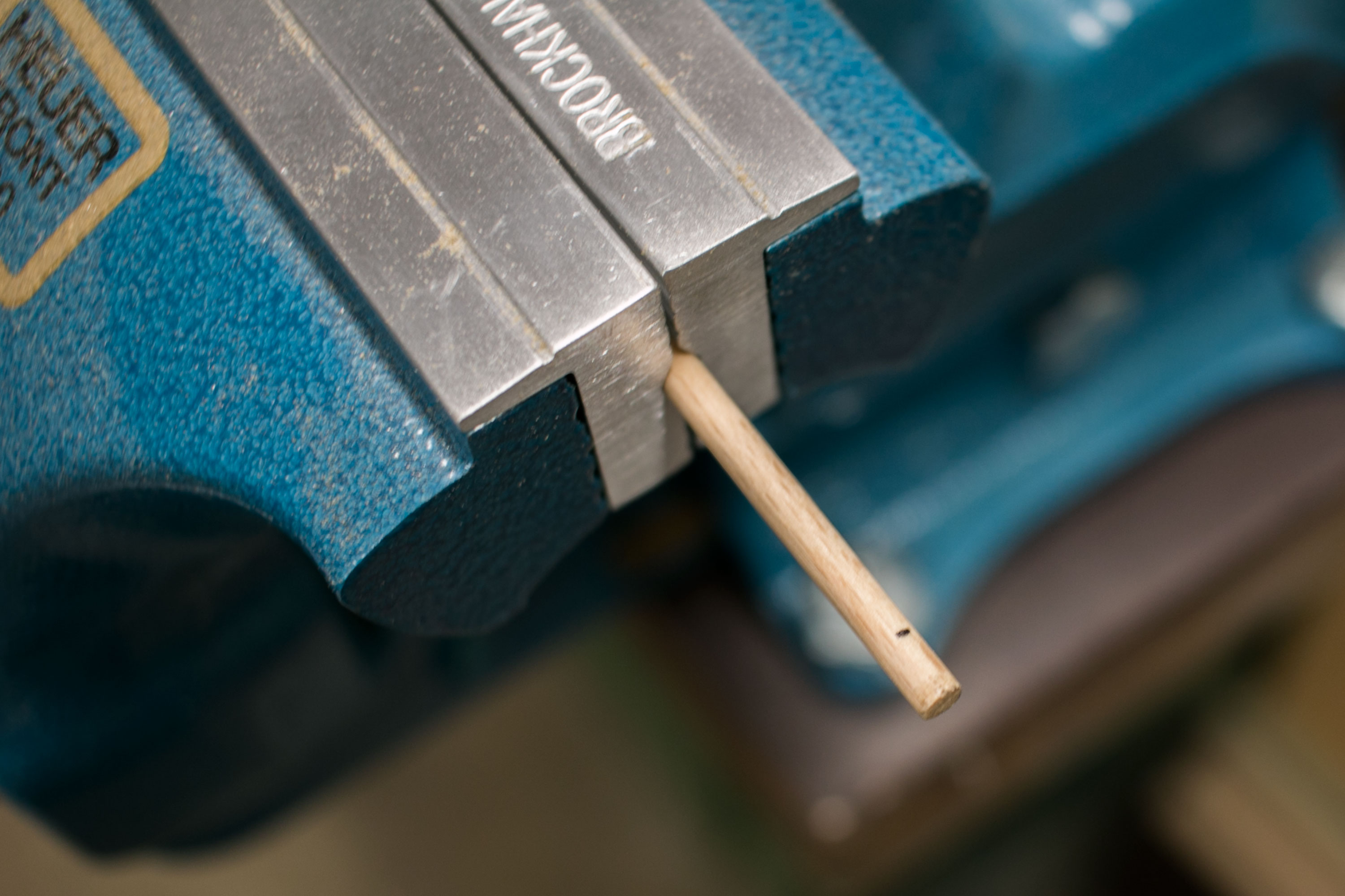
Next you will have to cut a wooden pole to the height of your three pieces. In my case 6 mm.
Gluing
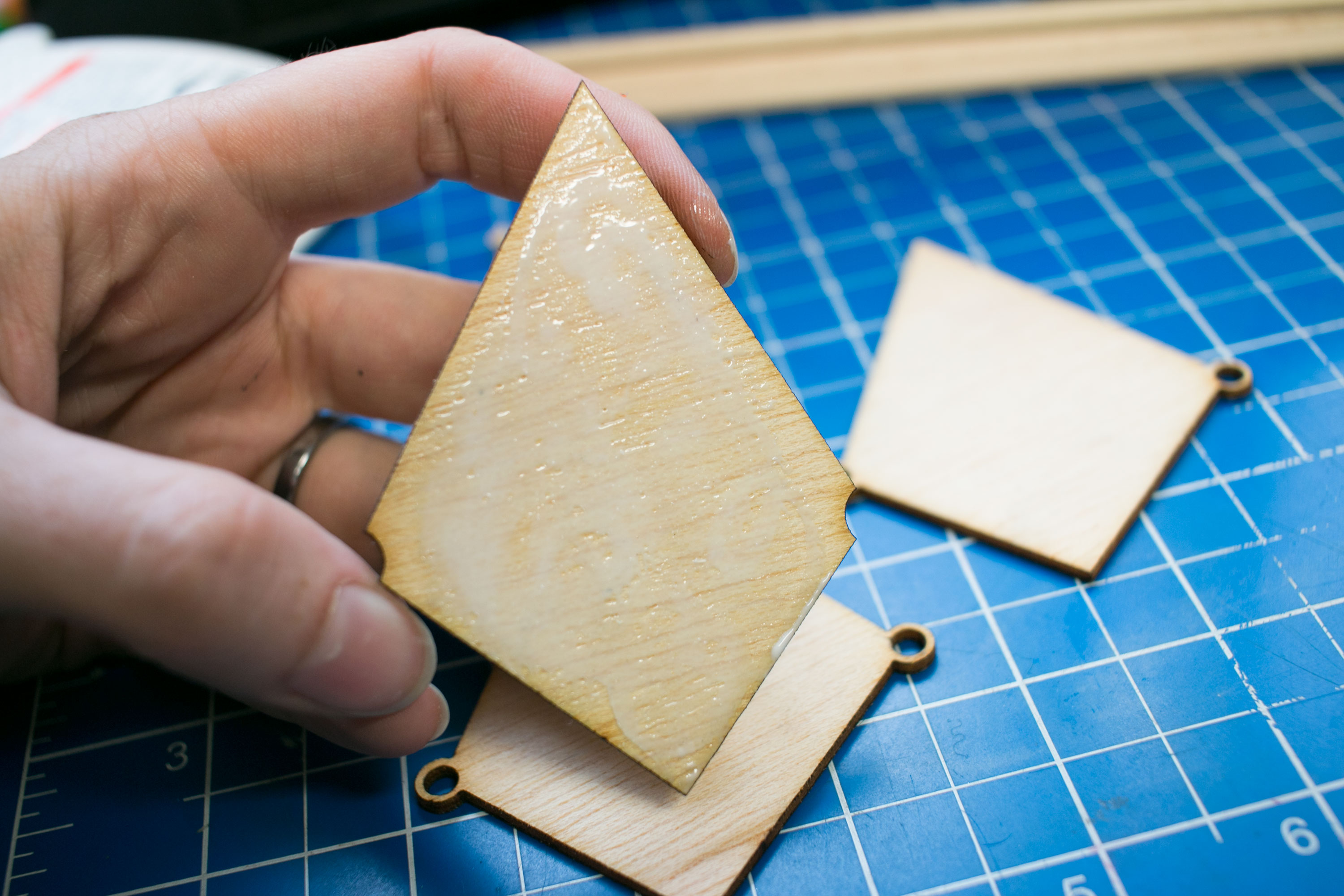
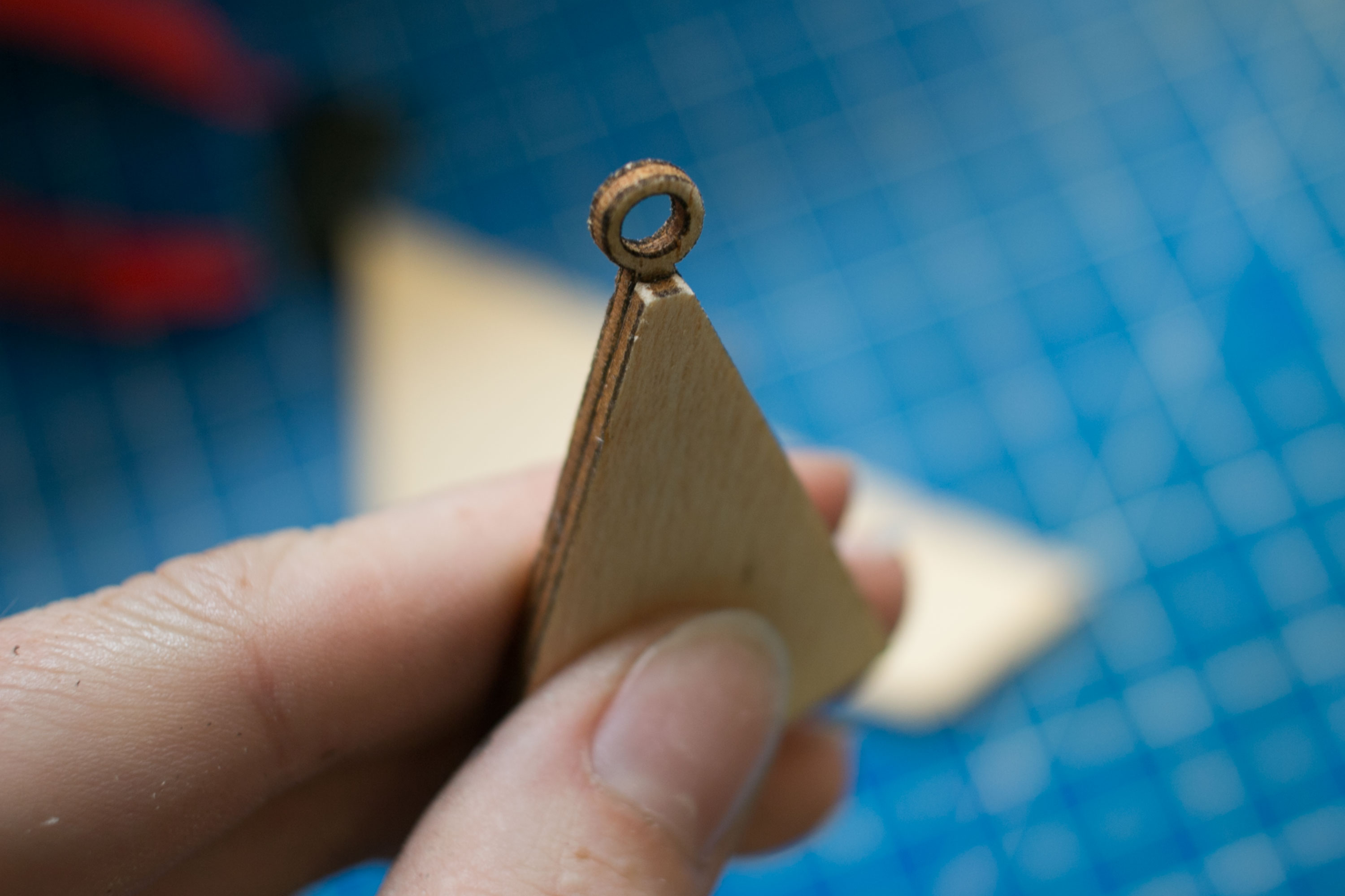
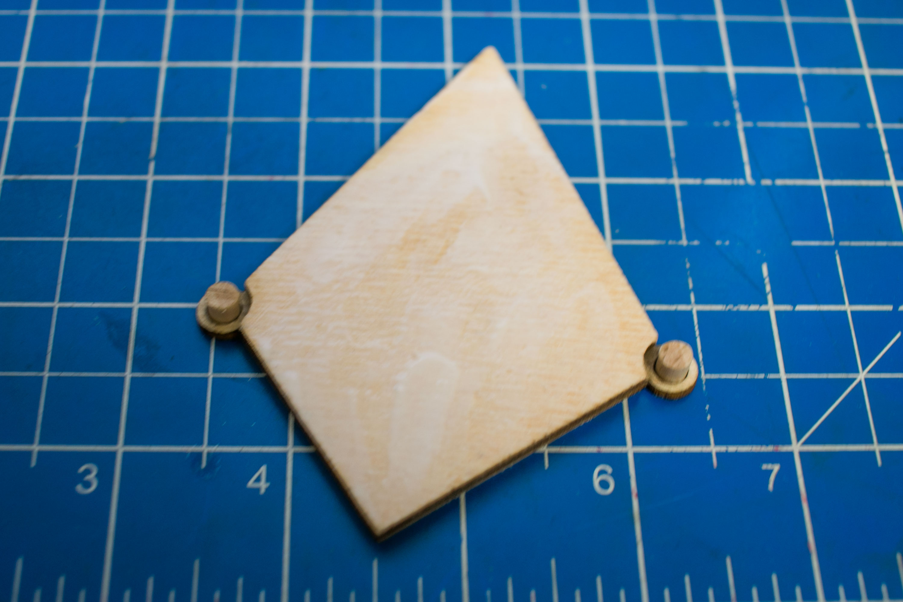
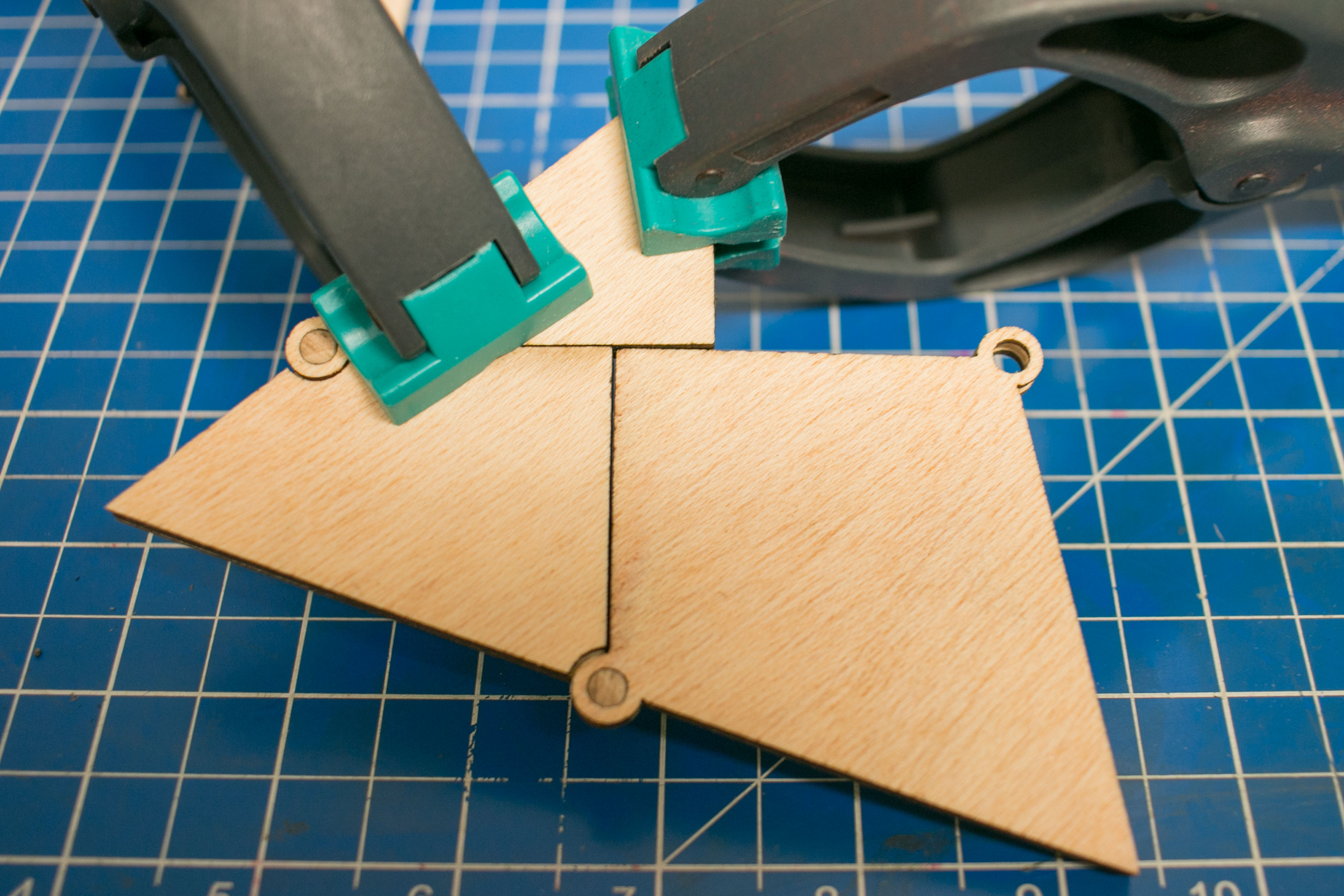
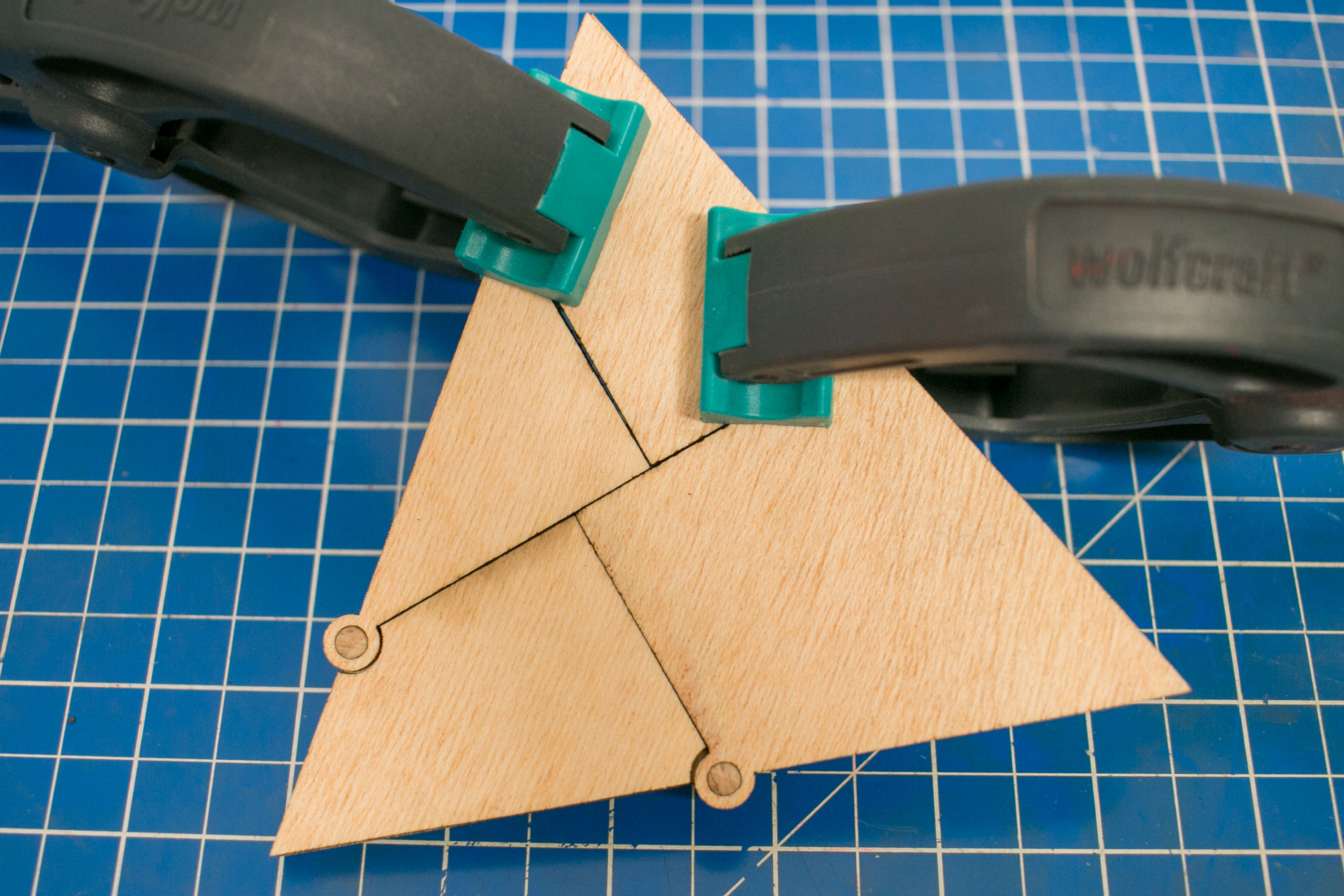
Now all that is left to do is to glue the pieces. Make sure to be precise, you might want to round the corners slightly, as shown in the second picture. Start by gluing the middle pieces to the bottom pieces. Clamp them and let them dry.
Now add your small wooden sticks and glue the top layer in place. Let everything dry again and sand all the pieces.
Congratulation you are done.