Dust Collector Monitor

This is a dust collector monitor. Both the dust bin level and the filter are monitored. My earlier dust collector project only monitored the bin level.
The video demonstrates the dust collector monitor detecting the filter needing cleaning. The threshold was set low to force this to happen for the video. Normally on my dust collector the filter would be considered loaded after the duct pressure passes 3" of water or 7.5hPa.
A lot of dust collectors, like mine, have a magnehelic that measures the static air pressure in the duct. You’re expected to periodically check it, and when it goes above some value, stop the dust collector and clean the filter. If you’re using a wide belt sander, the filter gets loaded much faster than if you’re using the jointer. The value the magnehelic displays varies depending on what gates are open. This makes determining when the filter is loaded somewhat arbitrary. I generally clean the filter at 3” because I can’t be bothered to check what the readings are for other gate combinations.
That’s one of the issues the monitor solves. In addition to acting like a magnehelic, it also knows which gates are open. When you clean the filter you train the monitor by running the collector, telling the monitor “this is what clean looks like." Most people would never run the collector with all of the gates closed or all of the gates open. There are a fixed number of gate combinations I generally use, and it’s based on what is attached to the duct branch. For example one of my branches serves both the jointer and the shaper. When I open the shaper gate I always close the jointer gate.
So, you’ve just cleaned the filter and started the collector. As part of the setup you open and close gates. Each time you setup a common gate combination you press a button on the monitor and mark this as “clean”. After that setup is done you run the collector till the filter is loaded. The monitor displays the static dust pressure, just like a magnehelic, so you need to monitor this (or your magnehelic) until you think the filter is loaded. When it’s loaded you leave the collector running and go through the same process you did to setup “clean” only now you do this for “dirty”. Once you’re done you’ve completed the monitor setup.
But what happens if I run the collector with a gate combination that I haven’t saved? In that case the monitor will use the first combination that’s closest to the current unregistered combination in terms of number of gates open.
For both clean and dirty you can set new thresholds at any time for any combination (although there is a limit of 32 gate combinations.) Obviously this should only be done when the filter is clean or dirty.
The other function the monitor performs is alerting when the dust bin is full. In addition to a flasher located above the monitor flashing when an event occurs, it will also break into the music on your FM or Bluetooth capable hearing protector headphones, with the message “Dust Collector Full” or “Filter Needs Cleaning”. I’ll describe what’s required to make this happen later on.
This ends the overview of the monitor.
The monitor board is available on PCBWay.
Update 12-Feb-2021: So far, so good. I've made a few changes to the software such as adding a panel to adjust and test the bin motor threshold.
Update 23-Feb-2021: Everything is working as expected. I'll share the boards on PCBWay in a few days. I rearranged many of the panels, the info panel can now show the load on the dust bin motor as one of the info options. In case anyone doesn't want to go through the hassle of wiring their shop with gate sensors, the code can now work without any gate sensors and will allow setting an overall clean and dirty level for warning when the filter is loaded.
The Board

There are actually 4 boards used in this project. The major boards are the monitor controller and the blast gate sensors. The other two are the display and 5 button boards.
I published a separate Instructable that covers the Blast Gate Sensor. You need a sensor for each gate you want monitored. Adding a gate sensor to each blast gate is optional but recommended. The monitor will work without blast gate sensors although determining when the filter is loaded won't be as accurate.
The 240x240 RGB display board is available on PCBWay
The 5 button board is also available on PCBWay
The monitor controller board uses a CAN or Controller Area Network. CAN was originally designed for use in vehicles. It allows devices attached to a common bus to communicate with each other. It’s very robust so it’s very well suited for use in an electrically noisy environment like a woodshop.
The monitor controller board sits on the CAN bus with the sensors. The sensors send a message to the controller whenever a gate is opened or closed. The controller can also ask each sensor for its current open/closed state.
Other notable devices/parts on the monitor controller board:
- Two BMP280 barometric pressure sensors. One sensor monitors the ambient room pressure, and the other the duct pressure. By subtracting the ambient pressure from the duct pressure you get a consistent static pressure reading.
- An RTC or Real Time Clock chip. This is used to set a file’s date and time when the file is written to an SD card. The RTC date and time can also be displayed in the Info panel of the display.
- An RFM69CW-433 MHz transceiver. This sends messages to the Audio Alert board that breaks into the audio stream on your headphones or sound system to notify you of a dust collector event that needs your attention.
- A Micro SD Card socket. Used to read and write configuration files.
- FFC (Flat Flex) connectors for the user interface’s display and 5 button board.
- XH2.54-3P connector for the dust bin level sensor/motor. See my Dust Collector Full Detector instructable for more details about how the level sensor works as well as how to build and install it.
- XH2.54-2P connector for the flasher warning light.
Downloads
The Software
This is an overview of the software used.
The only software that I didn’t write, other than the classes that are in the Arduino IDE bundle, are the classes that deal with the SD card and the transceiver.
- Bill Greiman's SdFat library. Copyright Bill Greiman 2011-2018
- Felix Rusu's RFM69 library Copyright Felix Rusu 2016
My MacOS utility application used in this project:
- SubsetFontCreator - creates a subset of a font for either 1 bit or RGB displays as compressed bitmap data (RGB is antialiased, 1 bit isn’t).
The primary class used on this board is DustCollector.
Class DustCollector:
- Is a subclass of MCP2515, a class that controls the MCP2515 CAN controller chip, that monitors and communicates with gate sensors.
- Monitors the dust collector to determine when the drum or filter is full.
- Controls the drum motor and warning flasher.
- Sends radio messages for two major events: dust bin full, and filter loaded.
DustCollector::CheckFilter():
The two pressure sensors are read every 1.5 seconds and averaged with the previous 4 readings to avoid sudden spikes such as when a door is closed. The two BMP280 pressure sensors are accurate, but they don’t return exactly the same value for the same pressure. When the dust collector isn’t running these readings are used to update a baseline pressure to negate this difference. This baseline is also used to determine when the dust collector is running. Once it’s running the difference in readings is the static duct pressure. This pressure is compared against the upper threshold for the current gate configuration to determine if the filter is loaded. If it is, then the flasher is enabled and a message is transmitted to the Audio Alert.
DustCollector::CheckDustBinMotor()
The load on the motor driving a paddle within the dust bin checked every 250ms. The value read is added to an 8 value ring buffer and an average of the ring buffer is made to determine the actual load on the motor. The ring buffer eliminates some of the spikes associated with turbulence within the dust bin based on the angle of the paddle relative to the air inlet. This average value is compared against the upper threshold to determine if the bin is full. If it is, then the flasher is enabled and a message is transmitted to the Audio Alert.
DustCollector::CheckGates()
This checks a flag set by the interrupt service routine associated with the MCP2515 CAN controller whenever a message is received from one of the gate sensors or a bus error occurs. When the state of a gate sensor changes, the gate set that most closely matches the new gate combination becomes the active gate set. The active set determines the upper and lower thresholds used by CheckDustBinMotor() and by the filter status meter in the UI.
The gates also use this mechanism to self register when you add a new gate sensor to the bus or are replacing a defective sensor. If all sensors are responding, a new gate is added without any action needed by the user. When a single gate isn’t responding the user will be asked if this new sensor is replacing the unresponsive sensor. If more than one gate isn’t responding, the user is asked to select the sensor name to be replaced or select “NEW” to add the unregistered gate as a new gate sensor. Without the ability to replace sensors the setup process would need to be repeated.
There’s a lot more to the software than this. The sources are available on GitHub.
Operation
When the dust collector controller is powered on, the quiescent duct pressure is established. For this reason the dust collector should not be turned on for at least 10 seconds after applying power to the controller.
Press any button to show the current selection. A flashing rectangle will be drawn around the current selection. If there is no button activity for 30 seconds, the selection rectangle will be hidden and the panel changes to Info. Pressing any button when the selection frame is hidden will show the selection frame.
By default, the Info panel is displayed on startup.
Info Panel:

Pressing the up button from the first line will display the Settings panel.
The first line of the Info panel displays the collector state icon and the filter status meter. The collector state icon is a round icon with fan blades. The collector state icon is dimmed/grayed when the collector is off. When the collector is running the icon is white and will animate between two icons to appear to be rotating. The filter status meter will reflect the static duct pressure when the collector is running. The range is based on the current gate set’s dirty/clean static pressure values. Default values are used when no gate sets exist.
The last four lines on the Info panel display user definable information. These lines behave the same. Pressing the left or right buttons while the selection frame is flashing will cycle through the available options. Pressing Enter will save the selected option. If the option isn’t saved, the last saved option will be displayed when the board is reset or restarted.
Available options:
- (empty/nothing)
- D: Duct pressure in hPa
- A: Ambient room pressure in hPa
- B: Baseline absolute delta between D and A in hPa periodically updated when the dust collector is off.
- S: Static duct pressure in hPa as the delta between D and A minus B when the dust collector is on.
- S: S converted to inches of water
- Time in the format HH:MM:SS AM/PM or without AM/PM if 24 hour format is selected.
- Date in the format DD-MMM-YYYY
- GS: The current gate set number or DEFAULT if no gate sets are defined. When gate sets are defined the number is followed by either EXACT or USING. Exact means the gate set is an exact match for the current combination of gates open or closed. Using means the gate set is the closest match for the current combination.
- M: WARN: The value is the current resistance on the bin motor, a number from 0 to 50. The sensitivity is the value at which a warning will be triggered. The sensitivity can be adjusted using the Bin Motor panel described below.
Settings Panel:

Pressing the up button from the first line will display the Info panel.
Selecting GATE SENSORS will display the Gate Sensors settings panel.
Selecting GATE SETS will display the Gate Sets settings panel.
Selecting SET TIME will display the Time/Date settings panel.
Selecting BIN MOTOR will display the Bin Motor settings panel.
Selecting SLEEP ENABLE/DISABLD will enable or disable sleep. Note that sleep will be enabled the next time the board is reset/restarted. There is no way to save this as a preference.
Gate Sensors Panel:

Pressing the up button from the first line will return to the Settings panel.
Use the up or down buttons to select one of the following:
The active gate name or number if the gate hasn’t been named yet. Pressing the left or right buttons will cycle through all of the gates. The displayed gate is the active gate.
Below the gate name is the gate status associated with the active gate. The gate status is one of OPEN, CLOSED or ERROR. When the gate status is OPEN or CLOSED, pressing enter from the gate name line will toggle the flashing of the gate sensor’s tricolor LED on or off. This can be used to identify the sensor. When the gate status is ERROR: ERROR is displayed when the sensor isn’t responding. The only time a sensor can be replaced is when it isn’t responding. By pressing enter you can unregister the gate. This should only be done if you aren’t planning on replacing the sensor for this gate. Once the gate sensor is removed, all gate sets that refer to this gate are also removed. Therefore, don’t do this if you plan on replacing this gate’s sensor. Simply replace the sensor, open or close the gate, and you will be asked whether this sensor should replace the sensor that isn’t responding with the newly installed sensor.
More detail: Normally, when an unregistered/new gate sensor is added to the bus and all existing gates are responding, the unregistered gate is automatically added as a new gate. If one or more gates aren’t responding when an unregistered/new gate sensor is added to the bus, a resolution panel will be displayed. From this panel you can select one of the gate names that aren’t responding or select NEW to add the unregistered gate as a new gate sensor. If one of the gate names is selected, the unregistered gate sensor will replace/be associated with this gate. Do not reinsert the previously unresponsive gate onto the bus without first clearing the ID stored on the board. Having two gate sensors with the same ID on the bus will result in unpredictable behavior. The assigned ID can be cleared by writing to 0xFFFFFFFF EEPROM location 0 on the board. The assigned IDs for all boards on the bus can be reset to the “factory” setting. See RESET below. Note that the sensor boards have a unique temporary ID as a static value in the Flash memory section. During the registration process the monitor controller board assigns a new ID that the sensor stores in EEPROM memory. Writing 0xFFFFFFFF to EEPROM location 0 causes the ID value stored in flash to be used.
RESET - Pressing Enter resets the gates and gates sets after selecting YES when a 2nd verification message is displayed. This operation should be used sparingly because you will need to redefine all of the gate names and gate sets.
CHECK GATES - Pressing Enter verifies that all gate sensors are responding. A status message will be displayed when the check completes.
NAMES: [SAVE, LOAD]
Use the left or right button to display either SAVE or LOAD.
SAVE - Pressing enter when SAVE is displayed will save the gate names to SD as a CSV file.
SAVED is displayed if the CSV was saved successfully.
NO SD CARD is displayed when no SD card is found.
SAVE FAILED is displayed if the CSV couldn’t be created/written. Save will fail if there are no gates.
LOAD - Pressing enter when LOAD is displayed loads the gate names from SD as a CSV file.
LOADED is displayed if the CSV was loaded successfully.
NO SD CARD is displayed when no SD card is found.
LOAD FAILED is displayed when the CSV file isn’t found or it isn’t a valid CSV with the expected fields.
You should always SAVE to SD prior to editing the CSV, preferably using a CSV editor such as the Numbers.app on the MacOS. Note that only UPPERCASE characters and a few symbols will be displayed. Also try to keep the names as short as possible otherwise they will be truncated (~12 characters max.)
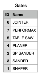
When you open or close a gate, the gate becomes the active gate displayed. The initial gate name is simply a number. Go through all of the gates and record its number. You then save the gate names (currently just numbers) to SD. Edit the file Gates.csv, substituting the actual names, then load the gates names from SD onto the monitor.
Example before/after naming gates.

Gate Sets Panel:

Pressing the up button from the first line will return to the Settings panel.
Use the up or down buttons to select one of the following:
SAVE [CLEAN, DIRTY, TO SD]
Use the left or right button to display either SAVE, LOAD or TO SD.
CLEAN - Pressing Enter when CLEAN is displayed will save the static duct pressure for the current combination of gates open/closed as a clean gate set.
COLLECTOR NOT RUNNING! will be displayed if the dust collector isn't running.
DIRTY - Pressing Enter when DIRTY is displayed will save the static duct pressure for the current combination of gates open/closed as a dirty gate set.
COLLECTOR NOT RUNNING! will be displayed if the dust collector isn't running.
TO SD - Pressing Enter when TO SD is displayed will save the gate sets to SD as a text file.
SAVED is displayed if the text file was saved successfully.
NO SD CARD is displayed when no SD card is found.
Note that the saved gates sets file is purely informational, it serves no other purpose.
Save will fail if there are no defined gate sets.
TEST SEND - Pressing Enter will send a filter full message to the Audio Alert if you have one.
RESET - Pressing Enter removes all of the gate sets after selecting YES when a 2nd verification message is displayed.
Set Time Panel:


Press the left and right buttons to move between the fields. Use the up and down buttons to increment/decrement a field value. Pressing Enter when a value field is selected will move to the next field. Pressing Enter when SET is selected will set the time and return to the Settings panel. Pressing Enter when CANCEL is selected will discard the time settings changes and return to the Settings panel.
Bin Motor Panel:

The sensitivity is the value at which the dust bin is considered full. This value is the resistance on the motor paddle within the dust bin. Use the left button to decrease the value and the right button to increase the value. The value set will be used as the new sensitivity. Unless the value is saved, the value will revert to the value saved in EEPROM the next time the board is reset. Pressing Enter will save the new sensitivity value to EEPROM.
TEST SEND - Pressing Enter will send a bin full message to the Audio Alert if you have one.
MOTOR [ON, OFF] allows you to test the bin motor when the dust collector is off. Use the left, right or enter buttons to turn the motor on or off.
CURRENT: , the value is the current resistance on the bin motor, a number from 0 to 50. By turning on the motor when the dust collector is off, and manually slowing down the paddle, you can get an idea if the amount of resistance the value represents.
Build the Controller Board

I don’t claim to be an expert at this. This is how I assembled this board.
I mount the board to a block of wood. This makes it easy to handle.
Start by applying solder paste to SMD pads on the front of the board.

Place the SMD parts. Don’t place the BMP280 till later. I have fewer problems if I apply flux to the ATmega644PA.

Using the heat gun, work your way around the board melting the solder and tweaking the parts into a more exact orientation with tweezers.
When you get to the BMP280, use your tweezers once the solder melts the BMP280 pads to ensure solder balls of the same size remain on the pads. Place the BMP280 and remelt the solder to attach it to the board.


Apply solder to the RFM69CW pads. Place the RFM69CW and melt the solder. I always do this separately rather than when placing the other SMD parts.
Turn the board over and apply solder paste to the SMD pads. Follow the same steps as used on the front side of the board.
Manually solder all of the through hole parts. I generally trim the through hole part legs before soldering. This looks better and it makes cleaning the board easier.
Clean the flux from the board.

Load the Controller Software
Download the project software from GitHub.
For this project you’ll need the MightyCore package installed on your Arduino IDE. MightyCore supports the ATmega644PA. If you don’t already have it, it can be loaded from the Manage Libraries dialog of the Arduino IDE.
Apply 6 to 12V to the board. Verify that you get 3.3 volts from the wide pad on the 3v3 LDO regulator.
Because the board has both 3v3 and 5V devices on the SPI bus shared with the ICSP connector, there’s a switch to disconnect the MISO line from the 3v3 devices. This switch is only used when you need to use the ICSP connector. Put the ICSP switch located next to the ICSP connector in the ICSP position.
From the Arduino IDE Tools menu, select the MightyCore ->ATmega644P. The default settings should be 16MHz external, BOD 2.7v, Pinout Standard, Variant 644p/644PA, Compiler LTO Disabled.
After selecting the port you have connected to your ISP, and the ISP, connect the ISP to the ICSP connector. On my boards I don’t install a 2x3 header because it’s generally only used once. I use a ICSP cable attached to a 2x3 set of pogo pins and simply hold it in place while burning the bootloader.

From the tools menu, select Burn Bootloader.
If the bootloader loaded successfully, put the ICSP switch in the RUN position. If not, then check the pins of the ATmega644PA for cold joints. I found that using a fine tipped soldering iron to remelt and brush the solder on each pin usually cures any cold solder joint problems.
Connect a USB to TTL serial cable to the TTL serial header. Upload the DCController.ino.
Leave the USB to TTL serial cable connected. Re-apply power to the controller board. With the serial output connected to any serial monitor with the baud rate set to 19200. Apply power to the board with the display and 5 button board temporarily connected, you should see the following:

The BMP280 status for both the ambient (front) and duct (back) is reported. You may see the error status -2 for either or both when first applying power. Try resetting by pressing the reset button on the board. If the BMP280s are responding correctly you should see a zero status for both. If you get -2 on either, then you probably have a cold solder joint. Remelt the solder holding the BMP280 that isn’t responding. Remove it. Apply a tiny amount of paste to any pads that look like they’re carrying less than the others. Remelt the solder to form balls on the pads. Check them again for consistent size, then mount the BMP280.
If the display is working correctly you should see:

Remove power from the board. Insert the CR2032 RTC backup battery. Set the time. Remove power from the board. Apply power to the board. Check the time. If the time isn’t correct, check the RTC chip and backup battery solder joints. Also verify that resistors R9 and R10 are the correct value (4.7K) and that they are oriented correctly (should be perpendicular to the RTC chip.)
Remove power from the board. Temporarily wire a gate sensor to the board with the termination switches on both boards set to END. Apply power and place a magnet under the hall sensor on the underside of the sensor board. The sensor should self register and the assigned gate number should appear on the monitor display. Also the RGB LED on the sensor should turn from blue to green. If this doesn’t occur then you may have a problem on either your monitor board and/or the sensor board. First try a different sensor. If that doesn’t work then check for cold solder joints.
Apply power to the board. Insert an SD card. From the Gate Sensors panel, select SAVE TO SD. You should see SAVED, assuming at least one sensor has registered, otherwise the save will fail. If you see NO SD CARD, then check the SD socket solder joints, specifically the tiny pads near the front right that determine if an SD is inserted. You can use a continuity meter to check the switch by placing one probe on the socket metal shell and another on the via hole located next to the card present pad. This switch is closed when a card is inserted.

Other Parts
Complete the following steps using the instructions in the Dust Collector Full Detector instructable:
- Step 16: Print the 3D Parts, just the motor mount and paddles.
- Step 17: Build the Cable Assemblies
You should not built the Status LED cable.
Note that the green static drain wire on the AC harness needs to be at least 11cm long, not 10cm.
See the photo below for the approximate length of the wires within the DC body.
The ends are terminated using Cord Pin End Terminals.
The static drain wire is terminated with a Dupont connector.

- Step 19: Insert the Motor Into the Motor Mount
- Step 20: Connect Control Box to Motor Cable
- Step 21: Mount the Motor Mount to the Drum Cover
Assemble the Controller Box
Print the 3D parts using the enclosed STLs.
I have an ‘OK’ printer, a homemade Ultimaker clone. The DC Body takes several hours to print so make sure your printer is well tuned.
The names “DC Body” and “Controller box” used below are synonymous.
For all:
- PLA, draft quality
- I used 80% fill. When I used 20% the loft used to support the controller board wasn’t strong enough. This was also true for the board mounting posts on the cover.
- support everywhere
- support overhang angle set to 80.
The Cable Mount should not be printed with any support. I printed these 6 at a time. You'll need a lot of them.
How I printed the DC Body:
For the DC Body you need to restrict/eliminate support for the area around the cable tie mount located on the bottom right front of the box. If this isn’t done support will be added within the slot you need to run a tie wrap through. Cura 4.8 has a standard tool for doing this.

The clamp for the AC power line uses (2) M3x16 pan head screws, (2) washers and (2) nuts. After removing the support from the clamp’s hex holes on the underside of box, without the clamp attached, push one of the M3x16 screws with a washer through one of the holes and thread it to a nut. Tighten the screw to pull the nut into the hex hole till it’s seated in the hole. Repeat for the other hole.
Using a G1/8 pipe tap, tap the hole for the pipe adapter. Depending on the accuracy of your printer, the print does have G1/8 NPT threads, but they need to be cleaned up using a tap.

The pipe adapter is G1/8 to 3.9 90 degree
Apply Teflon plumbers tape to the adapter threads.

Screw the pipe adapter into the DC body.

Disclaimer: Modification of your dust collection electrical control system should only be performed by a qualified electrician. Improper modifications may cause physical harm to you and/or your equipment and may void your dust collector warranty.
I have my controller box located just above the dust collector switch box. My collector uses a magnetic relay with the line lugs on the top of the relay and the load lugs on the bottom. The 18 AWG (minimum), 3 wire AC wire should be sized to reach whatever power source will be used (AC 110/220V, it doesn’t matter.)
It’s much easier to wire the 12V power supply when it’s not in the DC Body. Obviously don’t add the spade connectors for the dust collector switch box lugs till the wires are fished into the switch box otherwise they may interfere with the cable clamps on both boxes.


Thread the cut end of the AC power cable from the inside of the controller box till there’s only enough insulation to sit in the clamp pocket. Attach the clamp using the M3x16 screws+washers. This shouldn’t be super tight, just tight enough to keep the wire from pulling out of the controller box.

Mount the 12V power supply using (2) M3x5 screws.

With the DC Body flat on a tabletop, place an 11x7x2mm O-ring on the adapter gasket ring inside the DC Body. Install the monitor controller board using (5) M2x4 pan head screws. Note that you can easily strip the screw holes. Just tighten till just past snug.

Thread a 2.5mm wide tie wrap in the mount located on the box floor in front of the hole for the CAN bus wire. It’s easier to do this when the DC Body is on the tabletop.
Connect a 433 MHz PCB antenna to the IPEX connector. Adhere the antenna to the side of the enclosure.
Mount the display board and 5 button board to the cover using (8) M2x4 button head screws oriented as shown below.

Mount the strobe to its mounting cradle as shown below using (2) M3x5 button head screws.

Installation
Attach the flasher mount 3D print to the flasher using 2 M3x5 pan head screws.
To mount the DC Body and flasher to the wall I used (4) plastic wall anchors and (4) #8x3/4 pan head screws. I don’t know the metric equivalent.
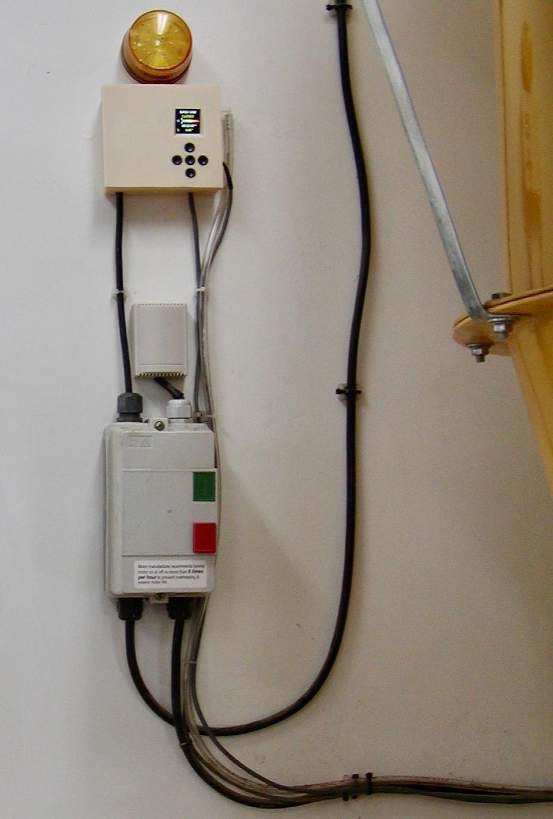
Place the DC Body containing the monitor board on the wall above the power source, reasonably close to the dust collector. The power supply in the DC Body will work on any 110V to 220V AC source. Mine is powered from the 220V lugs on the dust collector switch. Once you’ve determined the AC cable will reach the power source, mount the DC Body to the wall using plastic wall anchors and pan head screws. Without the flasher attached, place the flasher mount base on the wall above the DC Body, centered over the opening on the DC Body for the flasher cable. Mark the screw locations, then install plastic wall anchors, but don’t mount the flasher bracket to the wall yet. First remove the DC Body from the wall, fish the flasher cable through the flasher mount and into the DC Body. Remount the DC Body. Mount the flasher mount base to the wall. Pull any flasher cable slack into the DC Body. Set the flasher in its cradle onto the flasher bracket.

Plug in the 3 pin drum level sensor motor cable to the XH2.54-3P socket labeled Motor through the side of the DC Base.
Plug in the 12V power cable to the XH2.54-2P socket labeled 12V.
Plug in the flasher cable to the XH2.54-2P socket labeled Flasher.
Attach the cover with the display and 5 button board using (1) 8 conductor flat cable, and (1) 6 conductor flat cable. Both cables are 10 cm long AB (exposed contacts on opposite sides) with a 1mm pitch.

Install a Static Pressure Tip in the exhaust duct just before the filter. Check the manufacturer's instructions for installing a magnehelic on your collector. My collector is made by Onieda, and they have pretty good instructions describing where and how to orient the tip in the duct.
If you plan to keep your magnehelic, you can purchase a 4mm T here.
The tubing used is PVC, 3/16" ID x 5/16" OD. I would assume the metric equivalent is 4mm.
You can probably get smaller cut lengths at most home centers. Try to get PVC rather than Silicone. Silicone tends to be too soft.
Attach the other end of the PVC tube to the adapter on the monitor control box.
Wire all of the blast gate sensors and the controller board in a daisy chain configuration. Note that the controller board does not have to be at the end of the chain. The boards at each end of the chain should have their TERM switches set to END. The rest of the boards should be set to MIDDLE. I used high quality 24 AWG solid copper Cat5e cable.
I ran the Cat5e cable along the top of the ducts. I attached the cable to the ducts using a tie wrap cable mount I designed. These mounts print fast and are modified after they’re printed to fit the ducts by heating them with a hot air gun and pressing the softened plastic against scrap duct of various diameters. I found that using duct of the next size down results a curve with some down pressure.


For an adhesive I used (2) Double-Sided Mounting Squares.
You need to clean the pipe with window cleaner before applying the double sided tape.
This tape really adheres well provided the pipe is prepped properly.

How I assigned the 4 Cat5e wire pairs to the CAN connector lugs:
- green + white/green is the common ground wire connected to all of the lugs marked GND.
- blue + white/blue is the common V+ wire, connected to all of the sensor boards IN+ or 12V on the controller board.
- white/orange is CANL in. (all)
- white/brown is CANL out. (for middle)
- orange is CANH in. (all)
- brown is CANH out. (for middle)
The reason for the in and out wires for CANL and CANH above is that I only wanted a single wire to enter the sensor or the monitor controller boards. This is done, not only because it looks neater then having two wires feeding a sensor or the controller board, but because the enclosures only have entrance holes that support a single wire. Because only a single wire is used, this requires a junction for each sensor or controller board in the middle of the chain. At the junction you connect the common ground and V+ wires, then the CANL and CANH as per the drawing below.

Bean Type Splices work pretty well on Cat5e cable. Follow the manufacturer's instructions.
At some point I’ll design a small enclosure to hide the splices. Currently my splices are wrapped in electrical tape. It’s not very pretty.
Follow the steps outlined in Step 3 Operation for setting the gate names.
To keep out dust, place a piece of electrical tape over the SD card slot when the SD card socket isn’t in use.
Conclusion
I hope you liked this instructable. Send me a message if you have any questions.