Dual Polyhedra in Autodesk Inventor
by rotormind in Circuits > Tools
5927 Views, 33 Favorites, 0 Comments
Dual Polyhedra in Autodesk Inventor
Hello!
For my first project at Pier 9, I wanted to get up to speed with the Autodesk tools quickly. So I decided to model some "easy" things -- though the learning curve was steep, the tools are powerful and this turned out to be a great way to learn the ins and outs of Autodesk Inventor (I'm using the 2015 version, which has some interface differences -- not always significant, but sometimes frustratingly so as a lot of the documentation seems to be for Inventor 2014).
I've always liked the Platonic Solids for their beautiful symmetry and simplicity: there are only five of them. A neat fact is that each platonic solid has a dual that's formed by making the center of each face into a vertex. The tetrahedron is its own dual, while the cube and the octahedron are duals, as are the icosahedron and dodecahedron. A neat way to illustrate this is by nesting a platonic solid inside its hollow dual, so the vertices (corners) poke out the faces of the dual. This is also a way to show off 3D printing, as fabricating nested objects is difficult or impossible with conventional manufacturing, for example the traditional Chinese nested "Family Balls".
So let's make some polyhedra! There are several ways to go about this. If you are skilled at spherical trigonometry, you can calculate the dihedral angles at which the faces meet (or you can cheat and look it up). But there's an easier way using the natural constraints of the shapes. After all, there's only one way to build a cube out of six squares: if the edges are constrained to meet, all the angles will be naturally 90 degrees. Imagine building a cube from a bunch of squares hinged at the edges: after three edges at a corner are attached, there is no freedom for the hinges to move; the faces are locked in a perfect corner.
So that's the method we will use to build the polyhedra and their duals. Because of my inexperience with Inventor, it took me several tries: the path I show you here is the wisdom accumulated from Doing It Wrong. First of all, you can't do this in a Part (.ipt) file (the first thing I tried) because there's no easy way to enforce constraints like there is in an Assembly. But we will start with a Part file that is a face, and assemble the faces into a polyhedron.
Starting a Square Face
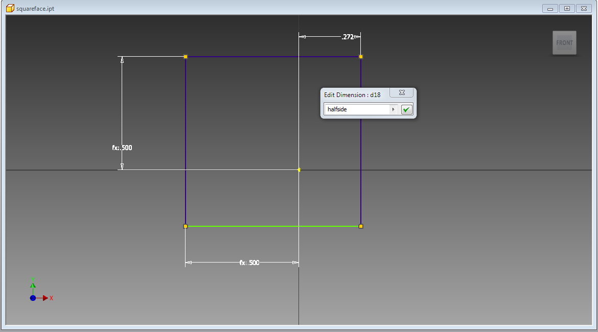
A cube is probably the easiest polyhedron to build, so let's start with that. You can call it a hexahedron if it sounds too simple! To make a one, start with a square face as shown above. Create a new Part (.ipt) file and start a new sketch: you can use any plane, but a pro tip is to project the origin (using the Project Geometry) command into any new sketch so there's always a good reference point. Because we want a point at the center of the face, let's keep the origin at the center and dimension four edges an equal distance away as shown.
Building a Solid Face
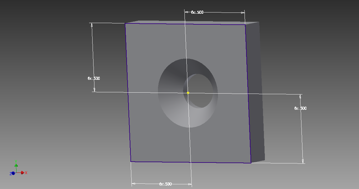
Once you have your square, you can Extrude it into a solid profile. You want a little thickness so you can select edges (as opposed to faces): I used a thickness of 0.2 of the cube edge length. Now this has two square faces, we will need to keep track of which face is at the origin, so let's add a Hole that's countersunk away from the origin. That way we can tell the difference between the two sides: the hole's wider side is on the origin plane. Save your part file.
Starting the Cube Assembly
Now that we have the side squares, we can assemble them into a cube. Start a new Assembly (.iam) file, and Place a side that you just made. You probably want to place one side Grounded at the Origin so use that option from the Place menu for your first square. Now place two more sides: to make assembly easier, rotate them in the X or Y directions in the Place menu so they wind up in the the right orientation in approximately the right place. Now might be a good time to go back to your Part and turn off the sketch visibility so the dimensions disappear.
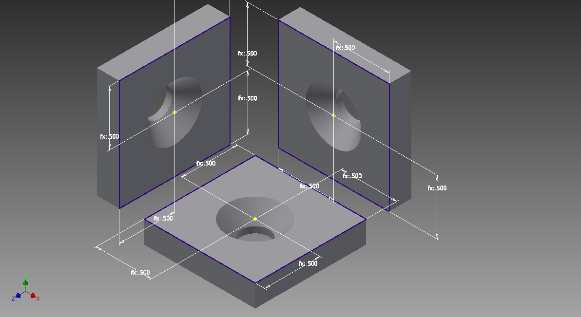
Constraining Your Faces
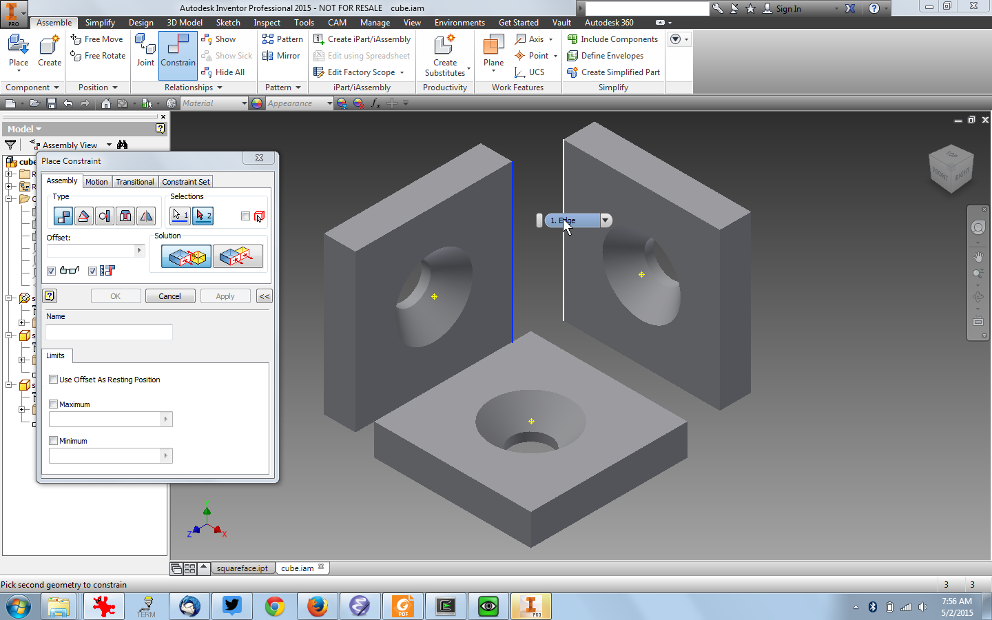
Here's the trick that makes this all work: constrain the edges of each face to snap together. From the Assemble menu, select Constrain: in the Constrain panel use a Mate type with an offset of 0.0. Click on two face edges and they will snap together. (If they don't meet, set the Offset to 0.0 and/or grab the part and slide it near its mate). Do this with the three edges between three faces and they will make a perfect corner! (Don't forget to select the edges on the origin face: the one with the wide side of the countersunk hole).
Add All the Cube Sides
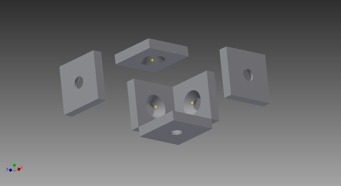

Add three more face squares, rotated as necessary, and constrain their edges to mate with their neighbors like before. You don't need to constrain every edge pair; two per face are enough but you can certainly do all of them if you are a completist. You will need to rotate your view to expose all the edges. When you are done you will have a chunky cube as shown.
Complete the Cube
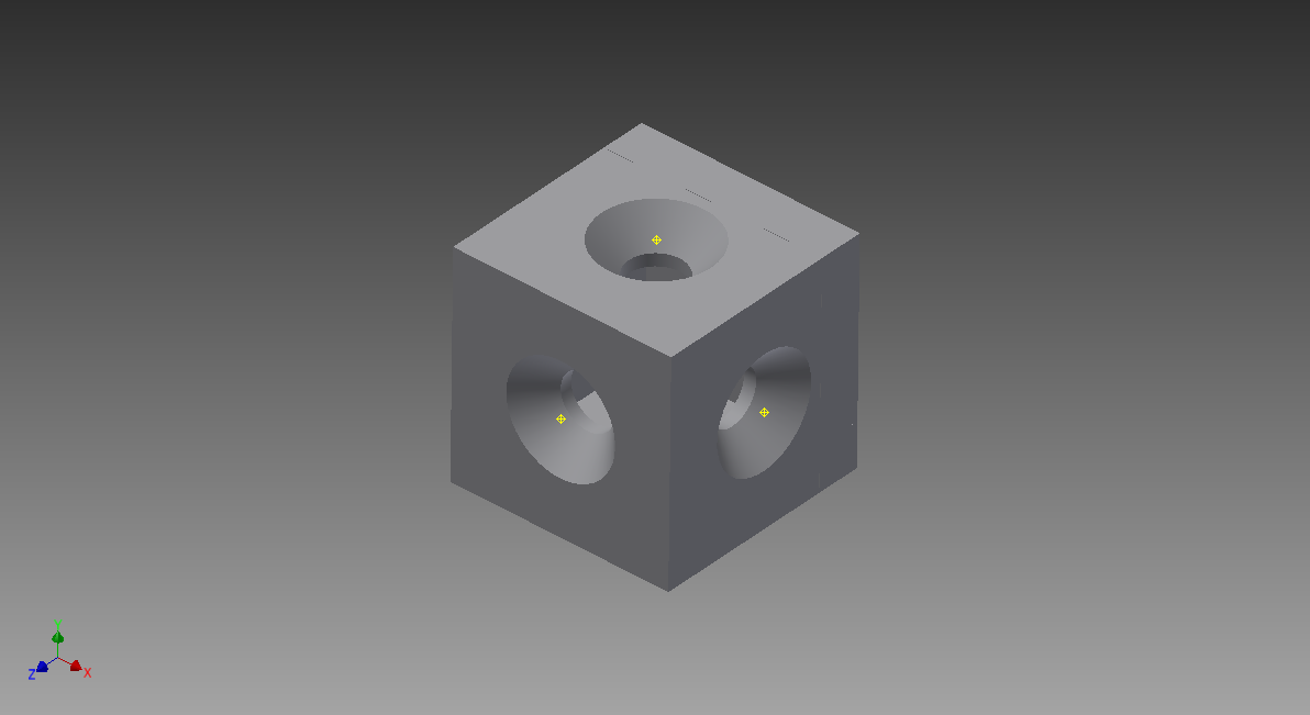
To complete the cube, go back into your face Part file, and change the Extrusion to the opposite direction. Right-click on the Extrusion feature in the menu, and reverse the extrusion direction by the icon button with the little black arrow. This means the face Extrusions are now internal to your cube: if you go back to the Assembly you will see the neat cube as shown.
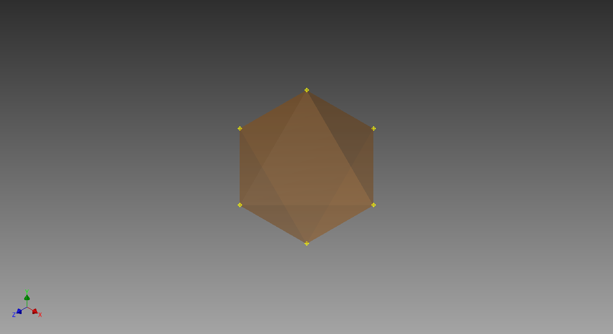
Create the Dual Octohedron Sketch
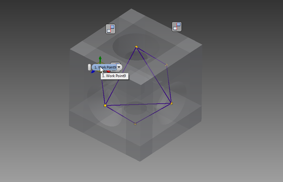
Each face of our cube has a center point, conveniently highlighted in yellow (because we Projected the origin in our original face sketch). Each is a corner of the cube's dual polyhedron: an octahedron. To construct this dual we just need to connect those points: lines between them are the octahedron edges. Annoyingly, you can't do this in an Inventor Assembly; we need to get back to a Part file before we can sketch in 3D. Because the documentation on this seemingly simple task is out of date, this took me a long time to figure out; but it's pretty easy, plus you get your new octahedron separated out in its own part file.
Here's how to do it in Inventor 2015: add a new empty part to your assembly from the Assemble->Product->Add Part menu. Double-click on your new part, this will gray out the cube because you are editing your new Part. Start a 3D sketch from the Sketch menu. Add edge lines between all the vertex points (face centers), the line tool will snap to each point and your line will turn constrained blue as shown. Only connect edges, so each vertex is connected to exactly four of its near neighbors: don't connect opposite corners through the center of the octahedron. Once again rotating your view helps to see where the neighbors are.
Convert the Octahedron 3D Sketch to a Solid
Once you've added all the edges, it's time to convert them into a solid. Finish the 3D sketch, then convert each triangular face into a patch by selecting the Patch tool in the 3D Model tab, and selecting the three edges of a face. Unselect the "Automatic Edge Chain" checkbox here. You will need to rotate around your model to get all the faces, as it's hard to see which faces have been completed because the patches are transparent. (There's likely a way to change this visibility but I haven't found it).
Once all the faces have been Patched, you can Stitch them all into a solid using the Stitch tool in the 3D Model tab. If you missed a face, it will complain: no worries, just make sure all the faces have a Patch. Then you can go ahead and save your new octahedron part, and go back to your cube Assembly.
Your Nested Hexahedron (cube) and Octahedron
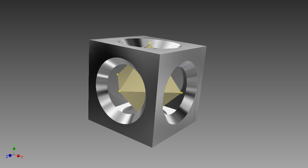
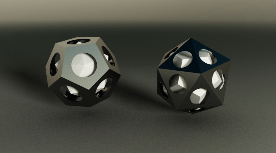
And there you go, you have created nested dual polyhedra! I made the cube face holes bigger so you can see the octahedron inside, and selected different materials for the rendering above. You can now 3D print these or whatever you want to do.
More Complicated Polyhedra

I showed the steps for a cube/octahedron dual because it was simple, but you can use the exact same steps to make any pair of Platonic duals. For icosahedra, octahedra, or tetrahedra, start with an equilateral triangle face. IN a tetrahedron, three triangular faces meet at a vertex; for an octahedron four faces meet; for an icosahedron five. To build a dodecahedron, start with a regular pentagon; three of those meet at a vertex. (See the duality? An icosahedral vertex has five three-sided faces while a dodecahedral vertex has three five-sided faces.)
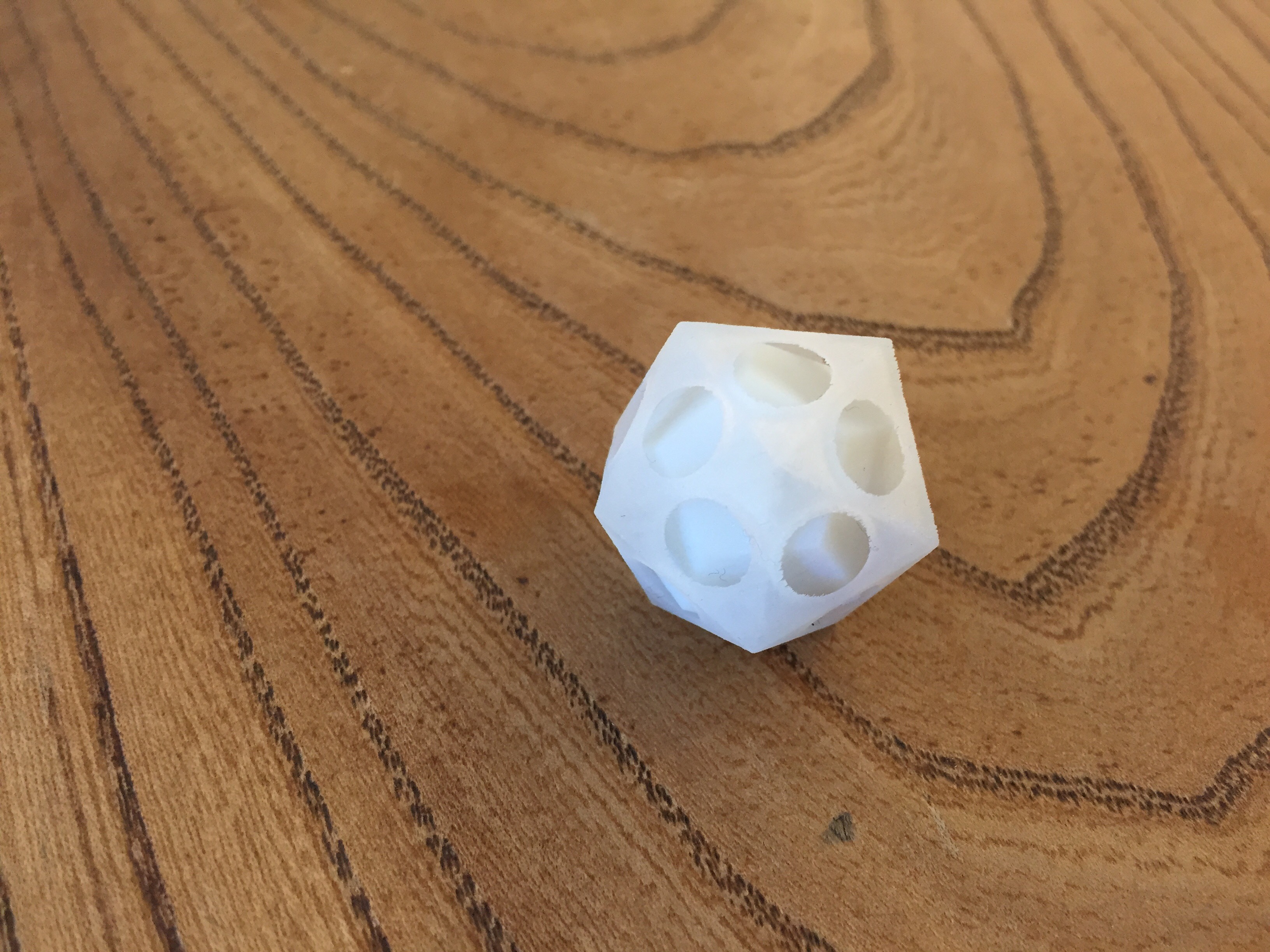
Unfortunately, it turns out that Inventor's constraint satisfaction system breaks down on the icosahedron: it can't easily be made from triangular faces using this method (though there may be constraint tolerance tricks that I haven't figured out yet.) To build an icosahedron from scratch, see my next Instructable; or you can do what I did here: create an icosahedron dual from a dodecahedron, and use that as a scaffold for triangular faces.
For the icosahedron above I printed a test version with a nested dodecahedron. I will print out the whole family when the printers at Pier 9 are reloaded with resins in contrasting colors so the internal duals are distinct. Until then, share and enjoy and I hope this helps you with your Inventor skills.