Drowsy Bob - Detects When You Get Drowsy While Working/Studying
by mondal3011 in Circuits > Arduino
6890 Views, 102 Favorites, 0 Comments
Drowsy Bob - Detects When You Get Drowsy While Working/Studying

.png)

Lately, I've noticed that I feel quite drowsy in class. Now I won't blame the lessons for being boring, and since I've been sleeping well at night, that's not the cause either. After doing some research online (mostly through Google and ChatGPT XD), I discovered that the drowsiness is probably due to excess carbon dioxide accumulating in the classroom. This makes sense, as the weather has been quite cold recently, and we keep the classroom windows and door closed most of the time.
The same issue occurs in my dorm. I feel drowsy while studying because I keep the windows closed, which causes the room to fill with too much carbon dioxide. Here's an article I came across if you’d like to know more: Read
At the exact same time, I came across this YouTube video talking about this issue and explaining how you can use CO2 sensors to monitor the CO2 ppm levels in your room. This way, if the levels rise too high, you can be notified to open your windows (or even set them to open automatically!).
However, there's a problem. Not everyone is tech-savvy enough to understand the ppm levels indicated, and those sensors can be quite expensive.
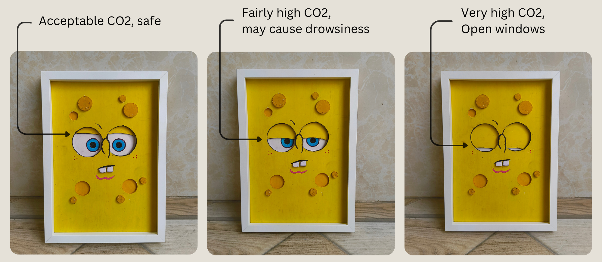
So, I came up with the idea of building a cool-looking CO2 monitor that is very intuitive to understand! It is basically an artwork of SpongeBob SquarePants (from the good old days!) whose eyelids move up and down to indicate how drowsy he gets based on the CO2 levels. When the CO2 levels are low, his eyes are wide open with his eyelids up. As the level rises, his eyelids gradually lower according to the ppm level. If his eyes are completely shut, it means there's too much CO2 in the room, and you better let some fresh air in!
Sounds interesting? Let me show you how I made it!
Supplies
Craft materials:
Sunboard (5mm and 3mm thick): Buy
IKEA RODALM frame 12x16'': Buy
Glue: Buy
Hobby knife: Buy
Paint
Paint brushes
Double sided tape
Electronics
Xiao esp32 c3: Buy
Seeed fusion PCB assembly Open
MQ135 air quality sensor: Buy
DC geared Motor: Buy
Hookup wires: Buy
Jumper wires: Buy
USB c cable
Hardware
Long M4 bolt: Buy
M4 nut: Buy
Pliers
Screwdriver
How It Works


The main components of this project are the MQ135 air quality sensor and a Xiao esp32 microcontroller. The setup also contains five hall effect sensors, each one mapped to a certain CO2 ppm level. A motor is connected to the microcontroller through an L293D motor driver IC. This motor is a DIY linear motor that moves the eyelids up or down depending on the direction of rotation. The eyelids contain a magnet at the long end that can be detected by the hall sensors.
The microcontroller reads the MQ135 sensor’s analog output and converts them to the CO2 ppm levels with some math. This is done for a specific duration (5 minutes in my code) and the ppm values are averaged for that duration. Then, the microcontroller turns the linear motor on until the magnet is in front of the hall sensor that corresponds to the same ppm (within a tolerance range). This way the eyelids move to match the ppm level.
This can be done in several different ways. My earlier plan was to have a linear variable resistor (also called a slide potentiometer) in place of the hall sensors and magnet. The slider would be connected to the eyelids. When the motor would move the eyelids up or down, the slider would move along with it and change the resistance. The microcontroller could map the ppm level to the right resistance to achieve the same effect of indicating CO2 levels with the eyelids. However, I later discovered that slide pots have a working life of about 15,000 cycles after which they don’t function well. Even if the eyelids move 50 times a day, the pot will reach end of life in less than a year. So that would not work.
Another way would be to use an ultrasonic distance sensor to detect the distance of the eyelids relative to itself. This is a feasible way. I came up with this only after I ordered the PCB with the hall sensors, so I stuck with that.
Designing the Circuit


For this project, I decided to design a PCB and have it assembled. I’ve never done it before and wanted to explore this. I’ve seen a lot of other creators at Instructables and Youtube make their own PCB so I thought this will be a good project to give it a go.
I used Easyeda for designing the circuit and PCB. There might be better alternatives out there, but I’ve seen a lot of youtubers use this and it seemed quite easy to learn. I will mention some tips and tricks as well as some good practices of PCB design I leant during my research in this tutorial.
I placed the Xiao Esp32-S3 in the middle and the L293D beside it to the left. It is a good practice to first place the bigger components and then add the smaller components later during design (the opposite applies while assembling a PCB!).
On the right are the five hall sensors. The digital outputs of the hall sensors are connected to pins D1 through D5 on the microcontroller. They are also pulled up through 10k resistors each. This way, when a magnet comes close to a sensor, the output of that hall sensor is pulled low.
The analog output of the CO2 sensor is connected to A0 of the microcontroller. Enable 1 of the L293D is connected to D8 and inputs 1 and 2 are connected to D6 and D7 respectively. The two motor outputs of the IC and the VCC are connected to two connecting blocks. The second motor inputs and outputs can be ignored since we are going to only drive one motor.
Before moving forward, it’s a good idea to check the nets to make sure all wires are connected at both ends and there are no bare terminals (except for the ones that are not required)
Designing the PCB


This part is going to be fun. Here, we will convert the circuit design to a PCB design.
First, I clicked on the "Design" menu and selected "Convert Schematic to PCB." EasyEDA then generated a new PCB file with all the components from my schematic. It's important to note that at this stage, the components are not yet arranged properly.
Next, I began arranging the components on the PCB. I started with the larger components, like the Xiao and the L293D. Connectors need to be placed near the edges of the board for easy access. I made sure to leave enough space between components for routing traces and to allow for easy soldering later on.
Once I was satisfied with the component placement, I started routing the traces. I began with the power and ground connections, making them wider than signal traces to handle higher currents. For sensitive analog signals, I used shorter, more direct routes to minimize noise pickup.
After I had placed all the components on the PCB, I decided to use the autoroute feature. I have never done routing before, so this feature is a Godsend! I clicked on the "Autoroute" button in the PCB toolbar. I chose to route all nets. (I later re-did this by skipping the GND nets. Reason explained later.) I then set the routing layers to use both top and bottom layers for a double-sided PCB. It’ll take a few seconds to create the routes after you hit “Run”.
After the autorouting was complete, I carefully reviewed the results. While autorouting can be a time-saver, it's important to note that it may not always produce the most optimal layout. Especially, it is recommended to have all angles at 45 degrees or lower. No 90 degree bends!
We’re not done yet. Where are the ground connections?! Well, we are going to add a copper layer for it. It is good to improve signal integrity and reduce electromagnetic interference.
First, I clicked on the "Layers" panel on the right side of the PCB editor. I then right-clicked on the bottom layer (assuming it was a two-layer board) and selected "Add Copper Area."
In the dialog box that appeared, I set the net name to "GND" to ensure this copper area would be connected to the ground net. I also adjusted the clearance value to 0.3mm (this is a good clearance value!)
Next, I drew a rectangle covering the entire board area. Once I finished drawing, the copper area appeared on the bottom layer.
To connect all ground connections to this new copper layer, I used the "Rebuild All" button in the copper area properties. This automatically connects all GND nets to the copper area.
Next, I ran the Design Rule Check (DRC) to catch any violations I might have missed. I carefully reviewed and corrected any issues the DRC highlighted.
Finally, I added text labels to the silkscreen layer for component references.
Generating Gerber files
To be honest, I am terrible at soldering. And soldering the whole PCB would be a nightmare for me. So, I decided to also have the components assembled as well.
I opted for the PCBA service by Seeed fusion. Since the Xiao board is also made by them, it was an advantage as I could give them specific instructions on how to assemble it.
For this, I proceeded to generate the Gerber files. In EasyEDA, I clicked on the "Fabrication" menu at the top of the screen and selected "PCB Fabrication File (Gerber)." This opened the Gerber generation dialog box.
In this dialog box, I saw a list of all the available layers for my PCB. I made sure to select all the necessary layers for manufacturing. I also selected the option to generate a drill file, which is crucial for the PCB manufacturer to know where to drill the holes.
Next, I checked the "Generate Gerber" option at the bottom of the dialog box. This ensured that EasyEDA would create both Gerber and drill files. I then clicked "Generate" and the Gerber file was saved to my PC.
You’ll also need to download the BOM file if you are opting for PCB assembly. The option to download this is in the top right corner in the schematic window.
Finally, I uploaded all the relevant files into the fusion PCB website. Since I am using the Xiao esp32 board, which is also made by the same company, I simply added instructions to use female headers in place of the microcontroller in the PCB design and later insert the Xiao into it.
Making SpongeBob SquarePants!


Well, my design currently features SpongeBob without his SquarePants. However, you’re more than welcome to add the pants yourself, there's no rule against it! For this project, I decided to use Sunboard, a type of low-density PVC board. It's incredibly easy to work with while still being remarkably durable, making it perfect for this kind of craft.
To start, I sketched SpongeBob’s design on a piece of A4 printer paper. This size is ideal as it fits perfectly into an IKEA frame and serves as an excellent reference point. Once I was satisfied with the sketch, I transferred the design onto the Sunboard using tracing paper.
Next, I began the cutting process. I carefully cut out some of the characteristic holes on SpongeBob’s body from the main 5mm thick Sunboard. For additional details, I created separate circular cutouts from another 5mm thick Sunboard and also cut out the eyes since we will have a separate back section for them.
Painting Him


I painted everything in SpongeBob’s classic yellow color, ensuring the base layer was vibrant and true to the character. To add more dimension and depth, I made the circular cutouts a darker shade of yellow. This contrast helped to highlight SpongeBob's iconic porous texture.
While working on the details, I also cut out SpongeBob's two teeth and the sections for the eyes and eyelids. For the eyelids, I painted them yellow to match SpongeBob’s face, and the eyes were colored in his signature blue and black. I made sure to leave a small length of Sunboard on the eyelids for attaching magnets later. The eyelids and eyes were made from 3mm thick Sunboard, so that they can move easily, while the teeth were made from thicker 5mm Sunboard to give them a more pronounced appearance.
In terms of painting, while spray paint is recommended for its smooth finish and ease of application, I chose to use acrylic paint for this project. It took three coats of acrylic paint to achieve a uniform and vibrant look I was aiming for. I also added a pink chin. Additionally, I painted some small red dots under the eyes.
Looks good, doesn’t he?
Making the Linear Motor


.jpg)

Linear motors can be quite expensive, so I decided to take on the challenge of making my own. Unlike traditional motors that rotate in circles, linear motors move in a straight line. Here’s how I made my own.
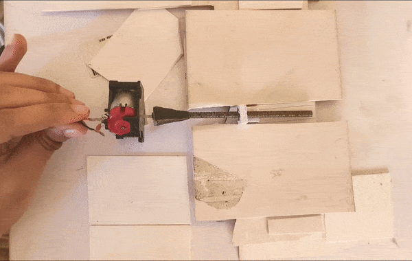
To begin with, I selected a long M4 bolt and an accompanying nut. These components form the core mechanism of the linear motor. Using a two-component adhesive, I bonded the bolt head to a gear that fits onto the motor. This type of adhesive is incredibly strong, but it requires at least 24 hours to fully set, so don’t touch it in between. I set it aside and waited for the adhesive to cure completely.
Once the adhesive had set, I proceeded to the next step. I took a geared DC motor and connected the bolt to its head. With the bolt securely attached to the motor, I powered on the motor. By holding the nut with my fingers to prevent it from rotating, it moved forward or backward depending on the polarity of the motor input.
This simple mechanism effectively created a linear motor! The motion was smooth and straightforward, exactly as intended. Also, the motor had good amount of force, so it is good for our application.
Testing the DIY Linear Motor


I tested the DIY linear motor by gluing the nut onto the eyelid section and securing the motor in place with double-sided tape. When I powered the motor on, I was disappointed to find that the eyelids didn’t move at all.
I realized that the positioning of the nut, which was placed at one end of the eyelid design, created a rotating motion instead of the linear movement I expected. This resulted in the sunboard getting stuck, as it was trying to rotate rather than move forward and backward as intended.
After a few attempts to troubleshoot the issue, the nut joint ultimately broke, which made it clear that this was a design flaw that I had to fix.
Modifying the Eyelid Design


I modified the design by repositioning the nut and the linear motor assembly to the center of the eyelid section. To accommodate this change, I had to cut a slit in the eye section that would sit directly above the assembly. This way the nut can freely move without obstruction.
This time, the movement was a success. The eyelids operated perfectly as expected. Although I noticed a some wobble in the mechanism, it was minimal and didn’t impact the overall functionality.
Modifying the CO2 Sensor


The MQ135 air quality sensor module was used for CO2 detection, and an important component in its functionality is the load resistor, RL. This resistor adjusts its resistance value in response to varying gas concentrations, which is essential for accurate readings. According to the MQ-135 datasheet, the load resistor can have a value ranging from 10KΩ to 47KΩ.
For optimal performance, the datasheet recommends calibrating the sensor using 100ppm NH3 or 50ppm alcohol concentrations in the air, suggesting a load resistance (RL) of approximately 20KΩ. However, if you trace the PCB, you’ll find a 1KΩ (102) load resistor in place. To accurately measure CO2 concentration values, it’s necessary to replace this 1KΩ resistor with a 20KΩ resistor. So, I removed the existing 1kΩ resistor and soldered two 10KΩ resistors in series.
Testing the CO2 Sensor


Make sure to preheat the sensor for 24 to 48 hours before proceeding. Preheating is basically leaving it plugged in to a 5v supply for the built in coil to heat up and remove any oxides formed.
Since we modified the resistance, we will have to make a few updates to the built in MQ135 library as well. First, download the MQ135 library in arduino IDE. Then, use the code attached in this step (get_r0.ino) to determine the R0 value. Now once you got the Ro values, Go to Documents > Arduino > libraries > MQ135-master folder and open the MQ135.h file and change the RLOAD & RZERO values. Rload is basically 20 (20kΩ).
Finally, upload the code (test_MQ135.ino) to your board, and you should see the PPM readings!
A small disclaimer. The MQ135 is not a dedicated CO2 sensor. It is sensitive to a range of gases including ammonia (NH3), nitrogen oxides (NOx), alcohol, benzene, smoke, and carbon dioxide (CO2). The sensor works by changing its resistance in response to the concentration of target gases in the air.
While I have tried my best to make it as accurate as possible with the code, it is no way close to the accuracy of some more expensive CO2 sensors like the MG812 or the SCD40. But the goal here was to keep the cost low to make it a compelling option over commercial smart home CO2 sensors. Also, we are categorizing CO2 ppm levels into five ranges, so the sensor doesn't need to be highly accurate. As long as we get relative information about high, mid, and low levels, we're good to go. And the MQ135 works perfectly fine for this application.
Testing the PCB


Once the assembled PCBAs and the standard PCBs had arrived, I needed to make sure they worked. One advantage of using Seeed Fusion for PCB assembly is that you can send them testing instructions and they will test the PCB for functionality (Functional testing) for free. I was in a total hurry and forgot to do this. So here’s how I tested my PCB:
First, I created a test code (attached to this step as test_PCB.ino). I uploaded the code to the Xiao esp32 (I soldered male headers to the board before that) and inserted it into the respective female headers on the assembled PCB. Then, I took a tiny neodimyum magnet and brought it closer to the first hall sensor. The serial monitor should display “1”. Which it did. Then I moved it to the second hall sensor. It displayed “2” as expected. I repeated it until all 5 sensors were tested successfully. You can do the same on yours. Or even better, you can send these instructions with the code to Seeed, and they will do it before shipping.
Downloads
Programming the Esp32


This section is intentionally small. I know the code is quite complex and this Instructable is already too long. If anyone is interested, please drop a comment, and I’ll add a step at the end with a detailed code walkthrough.
For this step, all you need to do is install the necessary libraries and upload the code attached (co2_sensor_1.ino).
Here is a good article that mentions the necessary libraries and how to install them: https://wiki.seeedstudio.com/XIAO_ESP32C3_Getting_Started/
Downloads
Making All the Connections


Now it’s time to assemble the SpongeBob artwork. Looking from behind, the main face board goes first, the eyelid section goes on top of it, then the eye section, then the motor is attached. And above all, the circuit is placed.
The connections on the circuit is pretty easy. Everything is labelled. I added a bare USB-C cable to the Xiao and connected to the 5v terminal (This could be done while designing the PCB, but I forgot :P).
Finally, place it inside the IKEA frame and it’s ready!
To Conclude...


The artwork looks amazing to be honest. The 3D effect due to the thick sunboard is definitely a plus. Now, you can know when SpongeBob (and hence you) get’s drowsy and open your windows to let the CO2 out! Isn’t that super cool? You and your artwork having the same amount of concentration at work haha.
I placed the CO2 sensor behind to hide it from view. If you do this too, make sure the frame is not placed in the corner of the room where there is no air circulation. Otherwise your SpongeBob might always be drowsy!
The eyelids do wobble a bit while moving, but that is not an issue at all. Since they only move when there is a significant difference in the CO2 levels, you will barely see them move. However it does make some noise while moving. Mainly because of my old geared motor grinding. I think a tiny N20 motor would be a better option.
You may have noticed something odd. I've used an Esp32 which is a Wi-Fi microcontroller, but this project doesn't use Wi-Fi. Well, the idea is to add some more code to enable tracking the CO2 ppm history in the room and send the data to the phone. This feature is in my to-do list and will be added soon!