Driving a New Bright Toy Bulldozer With an Intel Edison
by robotoys in Circuits > Microcontrollers
2483 Views, 9 Favorites, 0 Comments
Driving a New Bright Toy Bulldozer With an Intel Edison
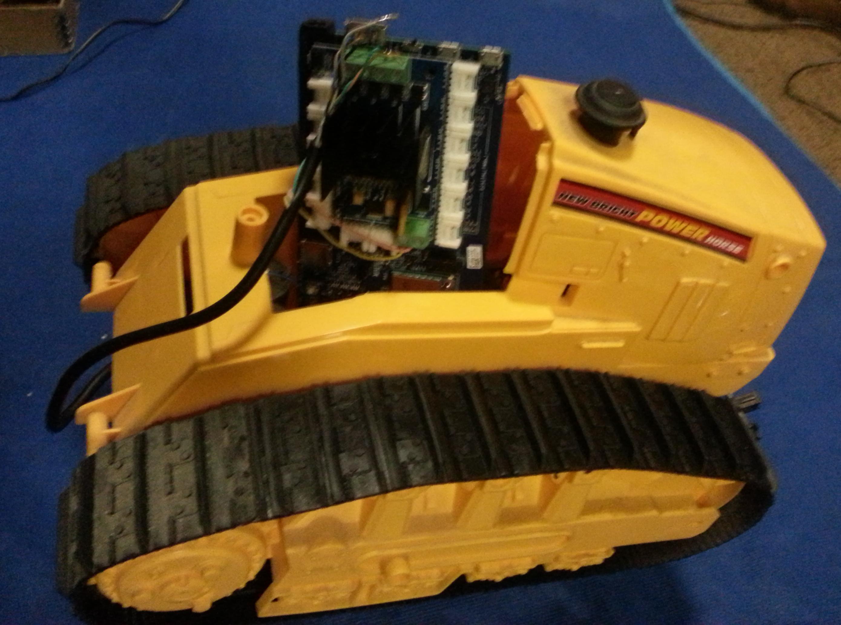
This instructable will present the steps needed to convert a tethered remote controlled toy bulldozer to an autonomous machine controlled by an Intel Edison microcontroller.
What you'll need:
- Battery Operated Toy Bulldozer with tethered remote (the example is from New Brite)
- Intel Edison with Arduino Breakout Board
- Motor Shield (the example uses a Grove Seeed Motor Shield V1.0)
- Diagonal Cutters
- Soldering Supplies
Disassembling the Toy Bulldozer
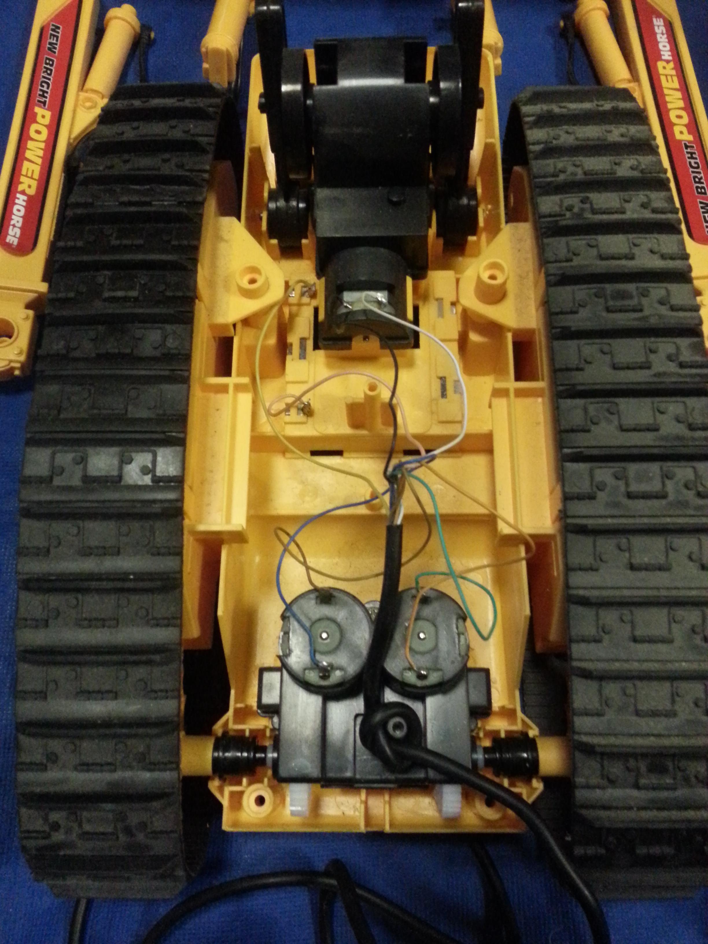
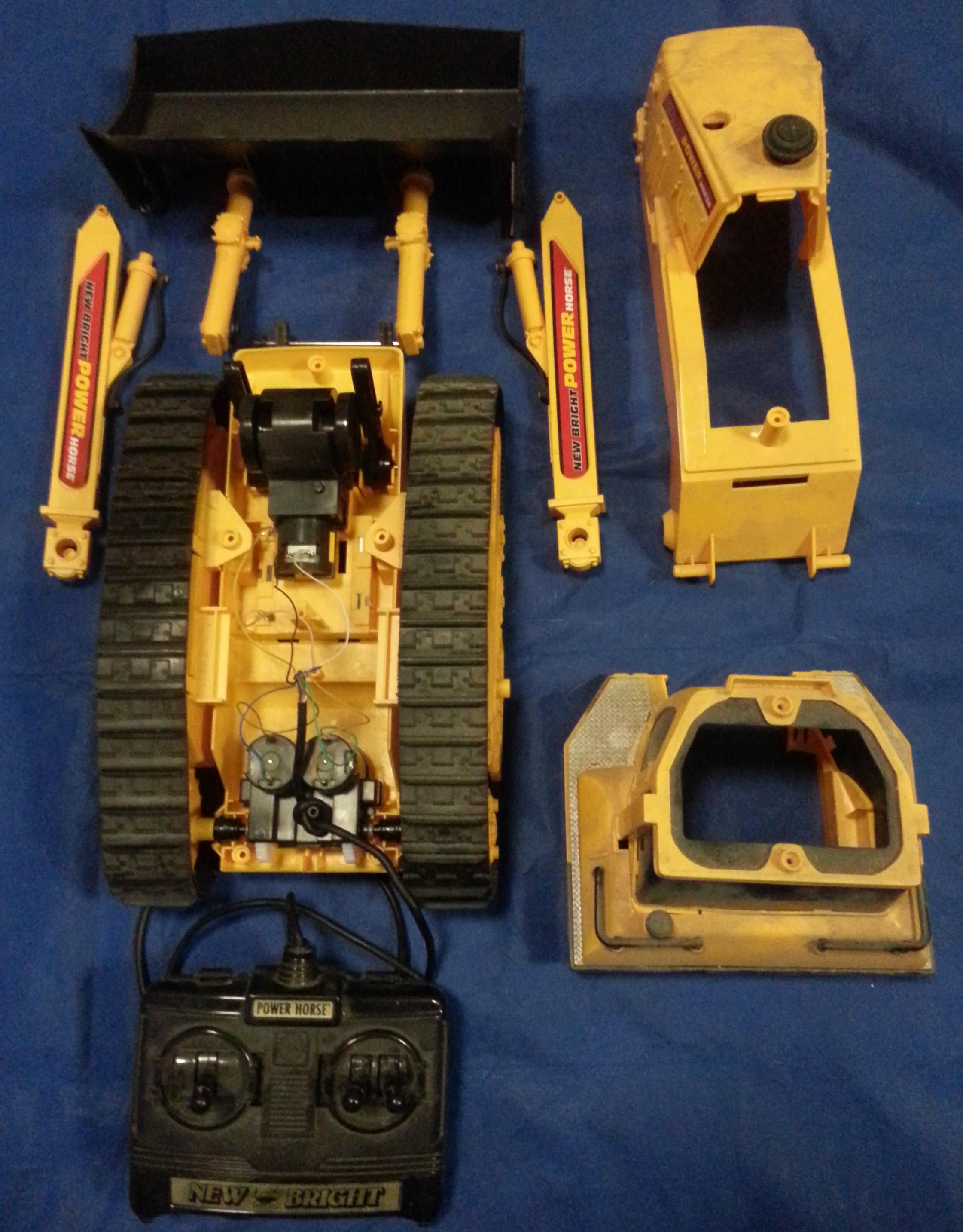
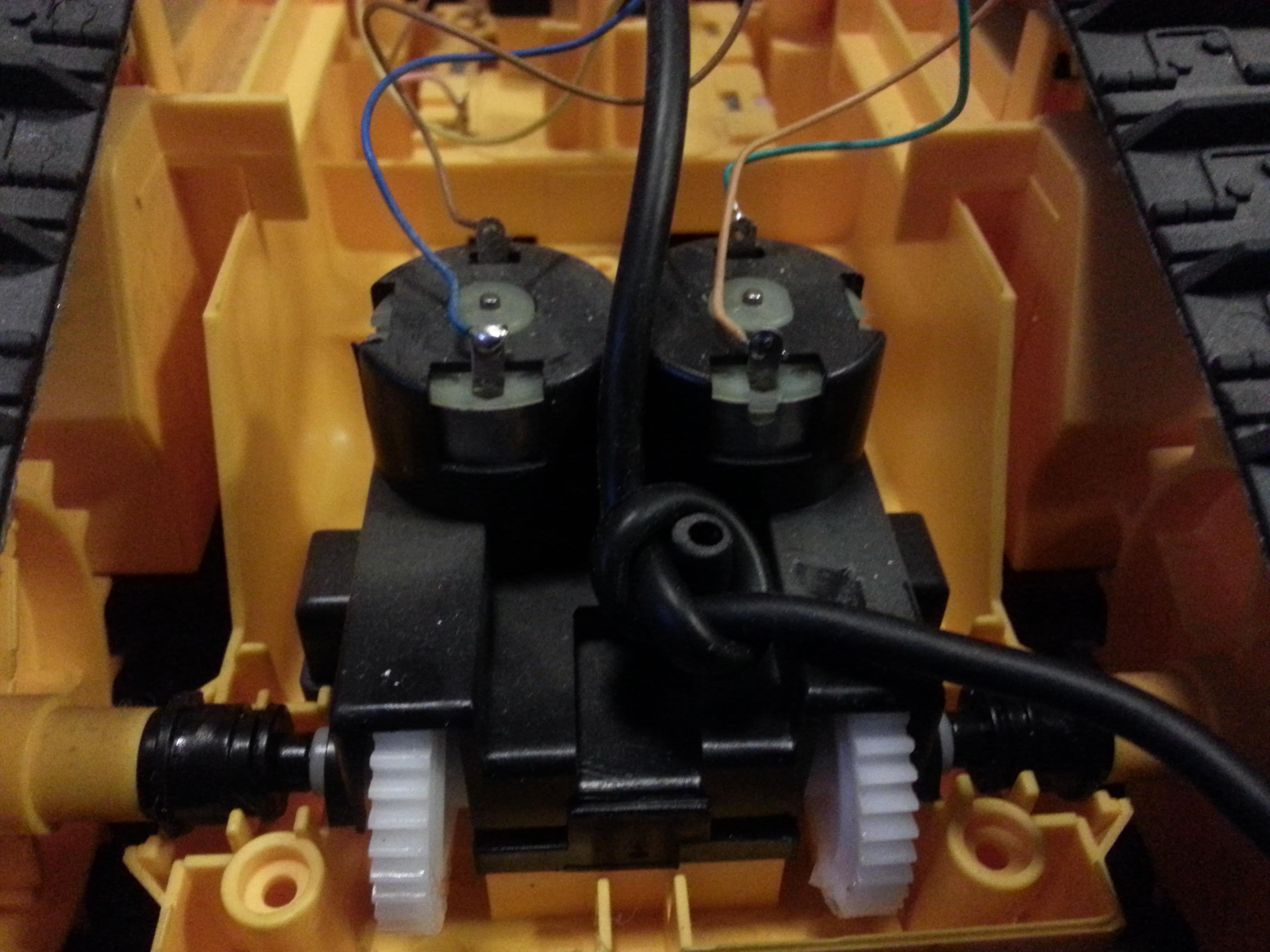
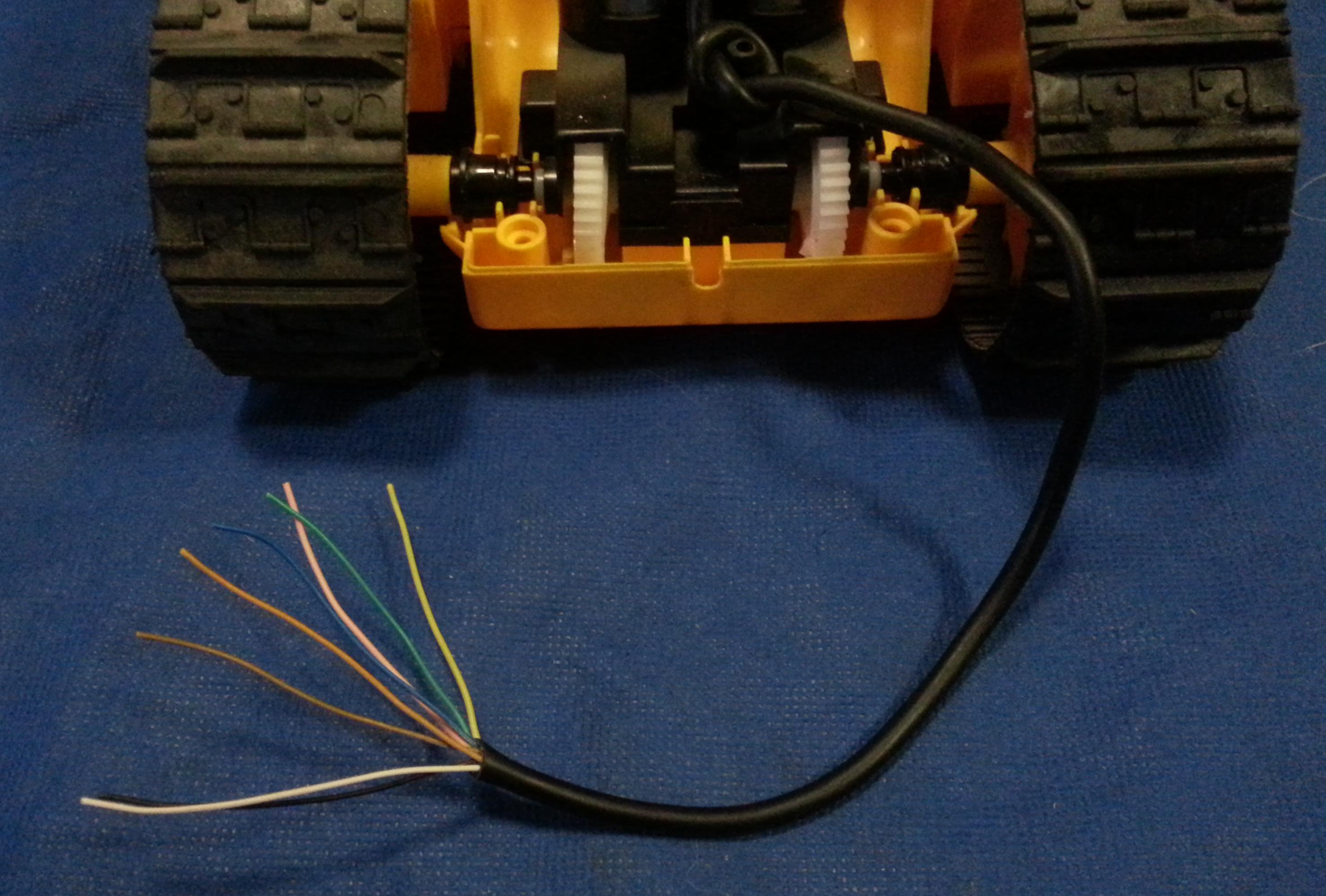
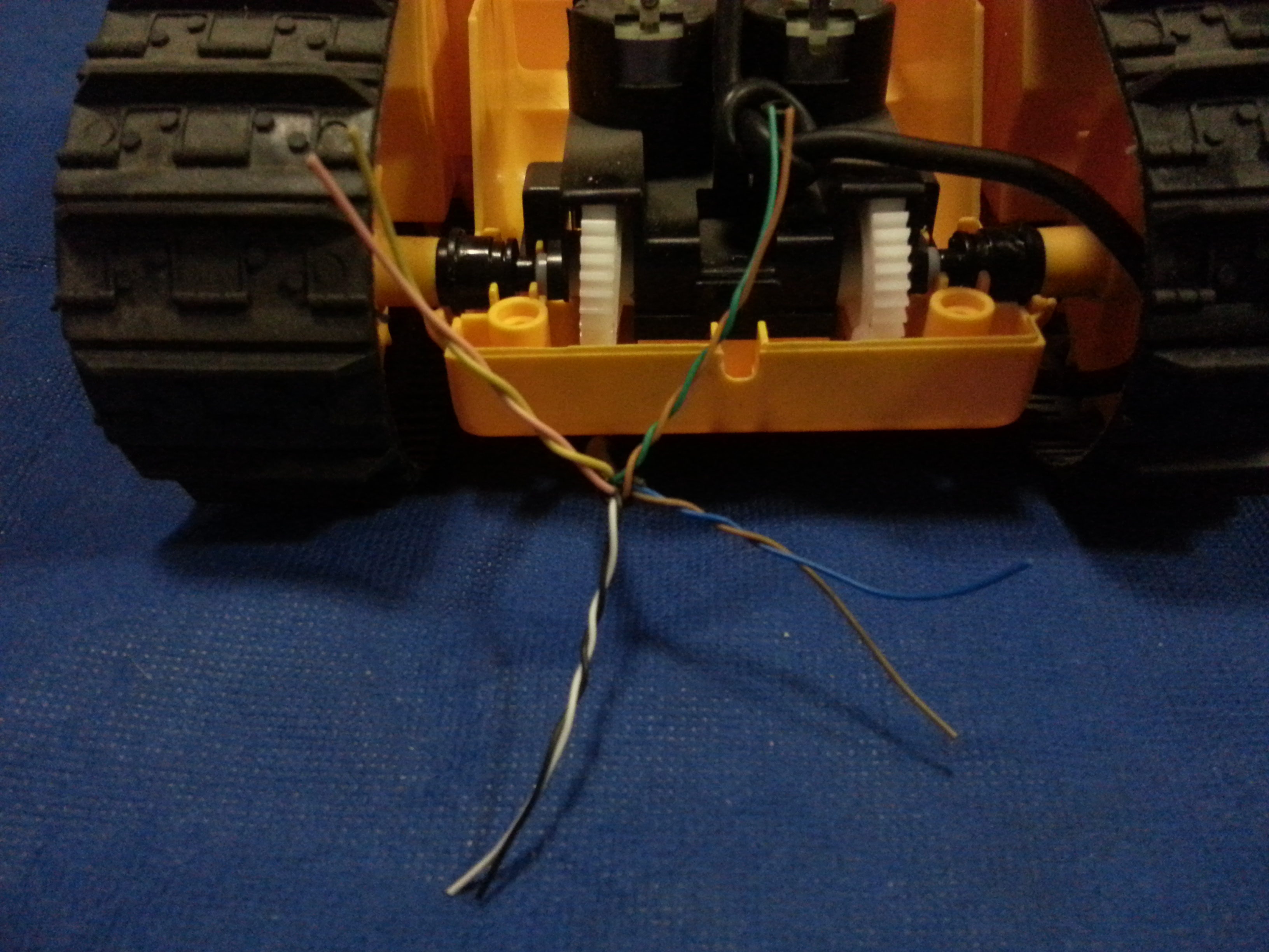
First you need to disassemble the toy bulldozer far enough to determine what the wiring connections are.
For the New Brite tethered remote bulldozer used in the example there are several screws in the bottom that hold the upper half of the plastic shell in place. The cab can also be separated from the main body to provide access to the motor compartment from the top after the main body is reassembled.
I opened the tethered remote and determined that the joysticks were simple switches shorting together motor control wires with the power and ground leads. Pushing the joysticks forward and backward would effectively apply the positive voltage to one motor lead or the other.
This particular booledozer has 4 AA batteries in a compartment on the bottom, two drive motors, and a motor to control raising and lowering of the front bulldozer blade. My interests for the initial development of the autonomous platform do not include use of the front blade, so I disassembled that part of the toy and set it aside for potential future use.
I measured out a sufficient amount of the remote control tether to reach the top of the chassis, and cut it with the diagonal cutters. After peeling off a length of the outer cover I matched the wire colors on the battery box and three motors and created the four related pairs. One pair carries the 6 volts from the battery pack. Three other pairs control the three motors.
Connect the Control Wires to the Motor Shield
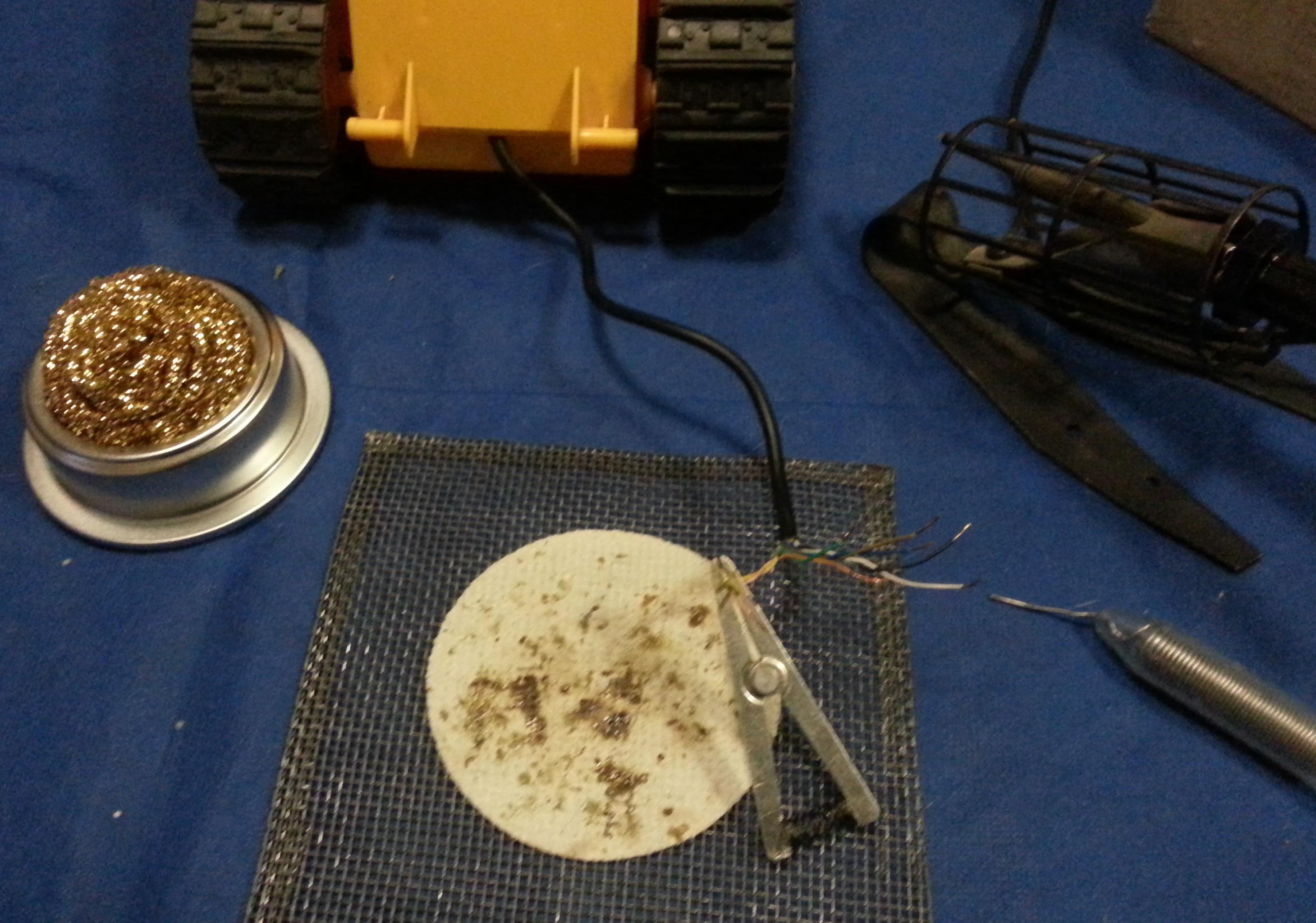
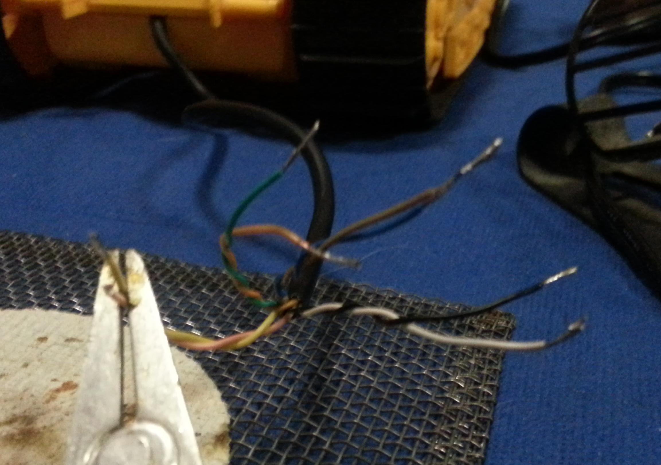
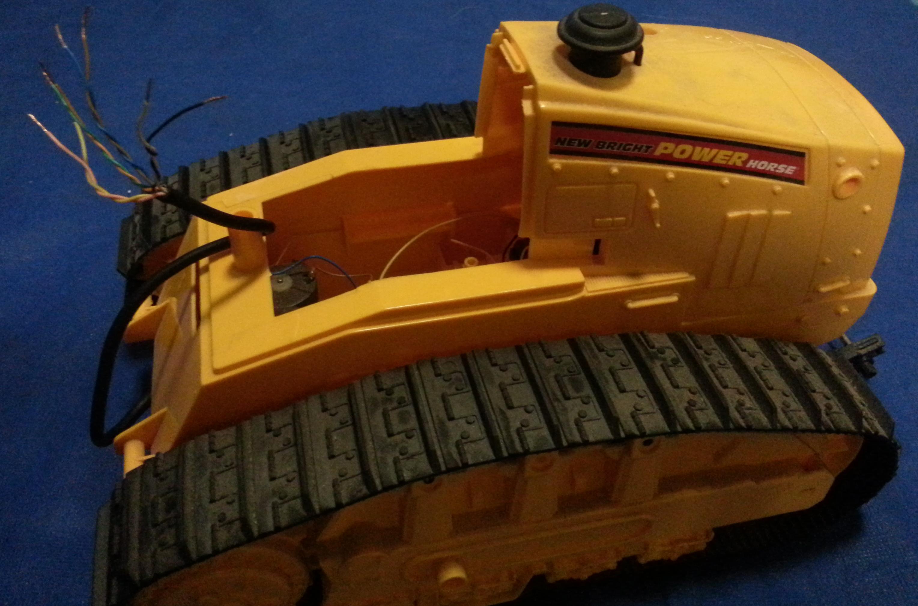
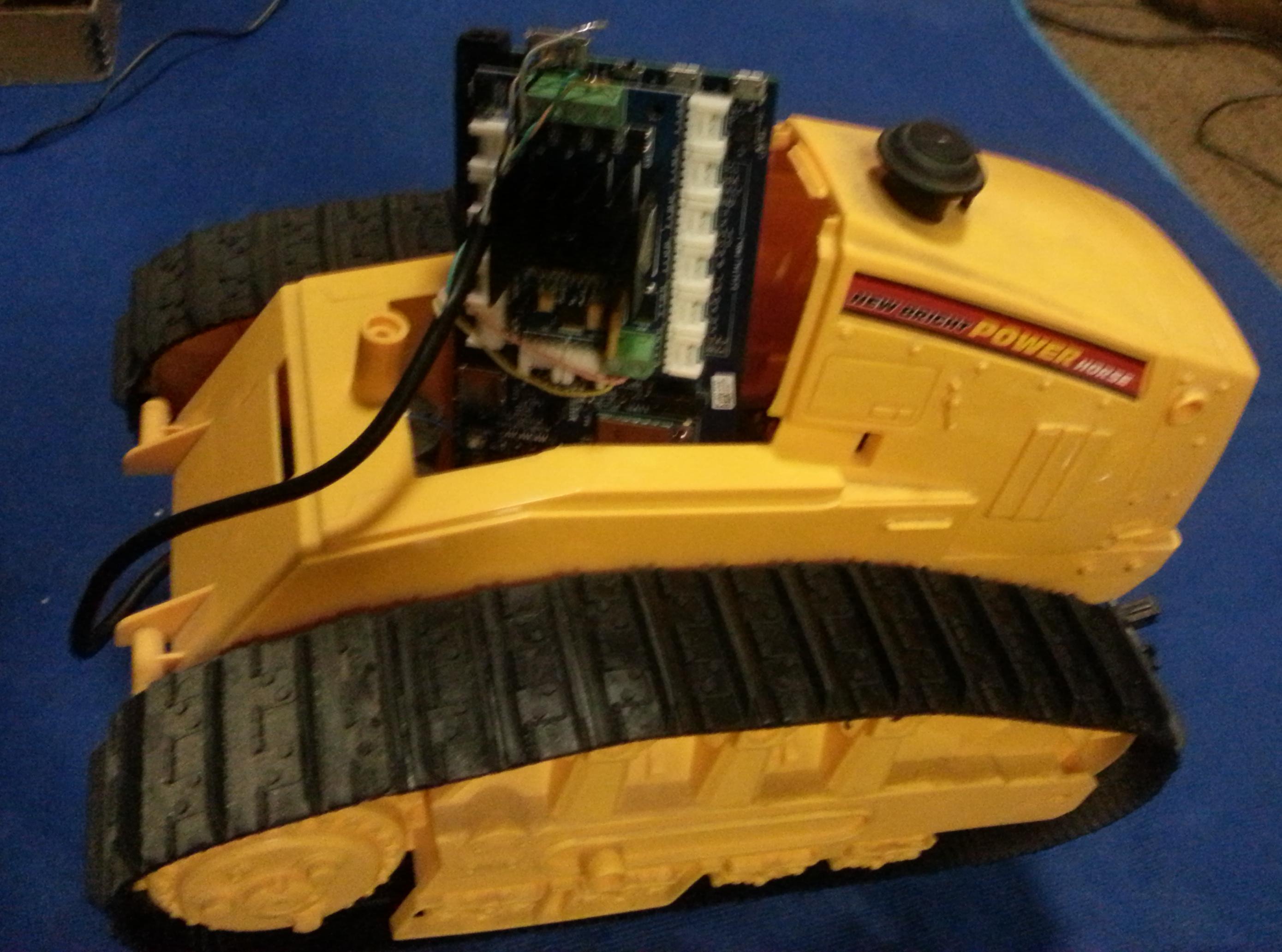
Strip off a length of each of the eight wires and tin the exposed wire to make it easier to connect to the motor shield.
My previous instructable describes how to get the Intel Edison configured to drive two DC motors through a Grove Seeed Motor Shield. You may have a different shield, but the basic steps are the same.
Connect the two leads from one drive motor to one pair of terminals for motor control on the shield. Connect the leads from the other drive motor to the other pair of terminals for motor control on the shield. Note that on this particular toy the motors need to spin in different directions for the dozer to roll forward or backward. You can either take care of that motor reversal by connecting one set backward on the shield, or by inverting all the directions in your motor control Arduino sketch. I chose to swap the motor leads on the shield so that the programming would be more consistently telling a motor to spin forward and having that track roll forward.
There is a jumper block on the shield that controls what the source of power is for the motors. Opening the connection between the pins on the Grove Seeed Motor Shield will cause it to drive the motors from the external power terminal block. Connect the battery box wires to the external power terminal block on the motor shield. This will cause the shield to use the bulldozer's batteries to drive the motors, and not put a current strain on the Arduino breakout board and its powering of the control logic on the motor shield.
Write the Control Logic for the Intel Edison
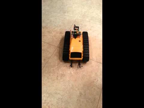
The initial testing of the motor drive connections was done with the motor drive Arduino sketch described in my previous instructable that interfaced the Edison to the Grove Seeed Motor Shield. It simply runs the tracks forward, backwards, left, and right, with pauses between each direction.
I did find that the original motor demo script that is widely circulated with Arduino has a quirk with how the stop() function was coded. All of the other motor movement functions write to the two motor speed pins with an analogWrite. The distributed motor control sketch uses a digitalWrite(pin, LOW) to stop a motor. For reasons not completely clear to me, the Intel Edison Arduino Breakout board talking to the Grove Seeed Motor Shield would not reliably catch the digitalWrite of LOW to stop the B motor. The motor would occasionally continue to move as if the stop command was never issued. I solved that problem by switching to an analogWrite(pin, 0) to set the motor speed to 0. That has reliably stopped the motor every time.
I have attached a copy of my modified motor driver sketch to this instructable for reference.
I have also included a short video showing the bulldozer whirring around under the Edison's control.
With the basics of the motor control hardware in place, any number of sensors and control logic can be programmed into the Edison for driving the bulldozer around. The bluetooth or wifi connection built into the Intel Edison could be used to control the booledozer from a handheld device or internet connection to the Edison.