Drawbot!
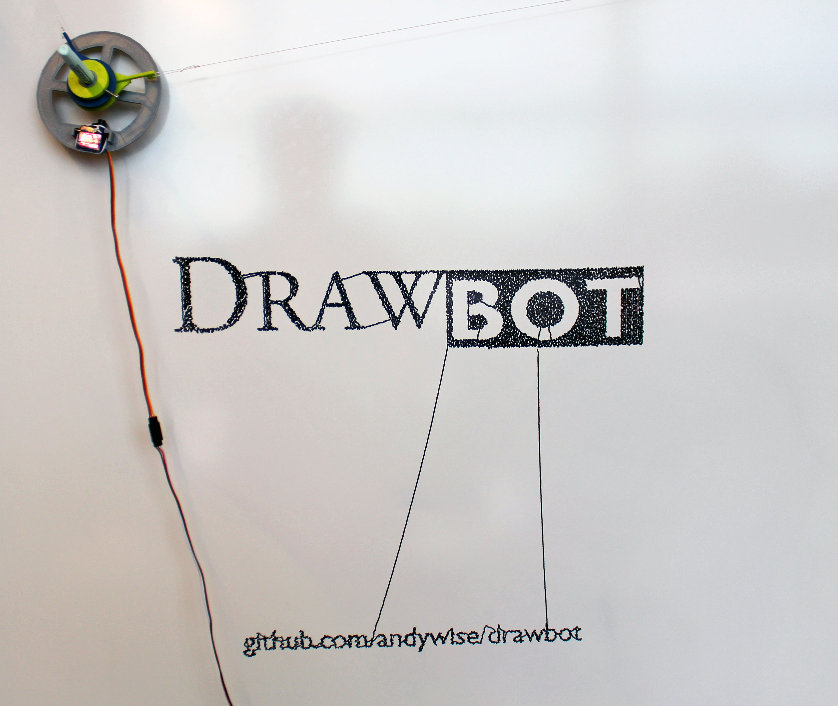
This instructable will document the construction of a Raspberry Pi controlled drawing robot that allows you to turn any flat surface into a canvas. Once you've built the drawing robot you'll be able to calibrate and send drawings to it via WiFi.
*This was built in the Black & Veatch MakerSpace from plans created by MakerSpace patron and creative wonder Andy Wise. See the Drawbot project on Github by Andy for more information.
What You'll Need
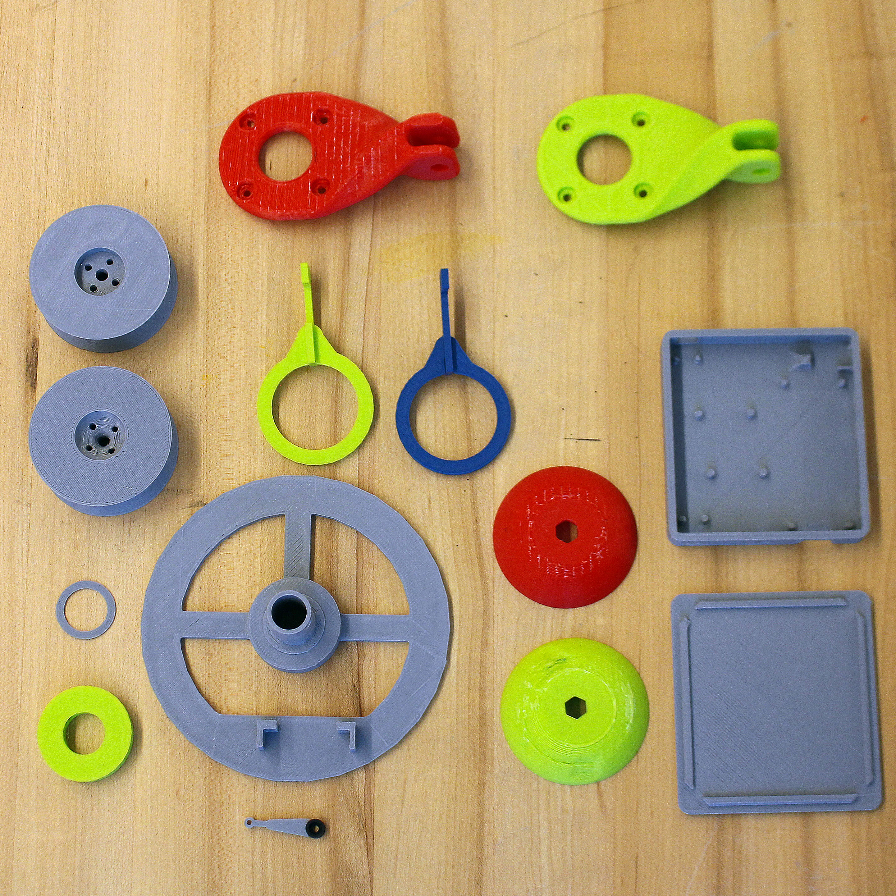
3D-Printable parts:
Polargraph gondola - https://www.thingiverse.com/thing:372244
Servo horn extension - https://www.thingiverse.com/thing:2427037
Drawbot motor mount and spool (x2) - https://www.thingiverse.com/thing:2427037
Drawbot electronics case (optional) - https://www.thingiverse.com/thing:2427037
Drawbot Pi + Stepper mount (optional) - https://www.thingiverse.com/thing:3122682
Suction Cup Dome with hole(alternative) - https://www.thingiverse.com/thing:3132569
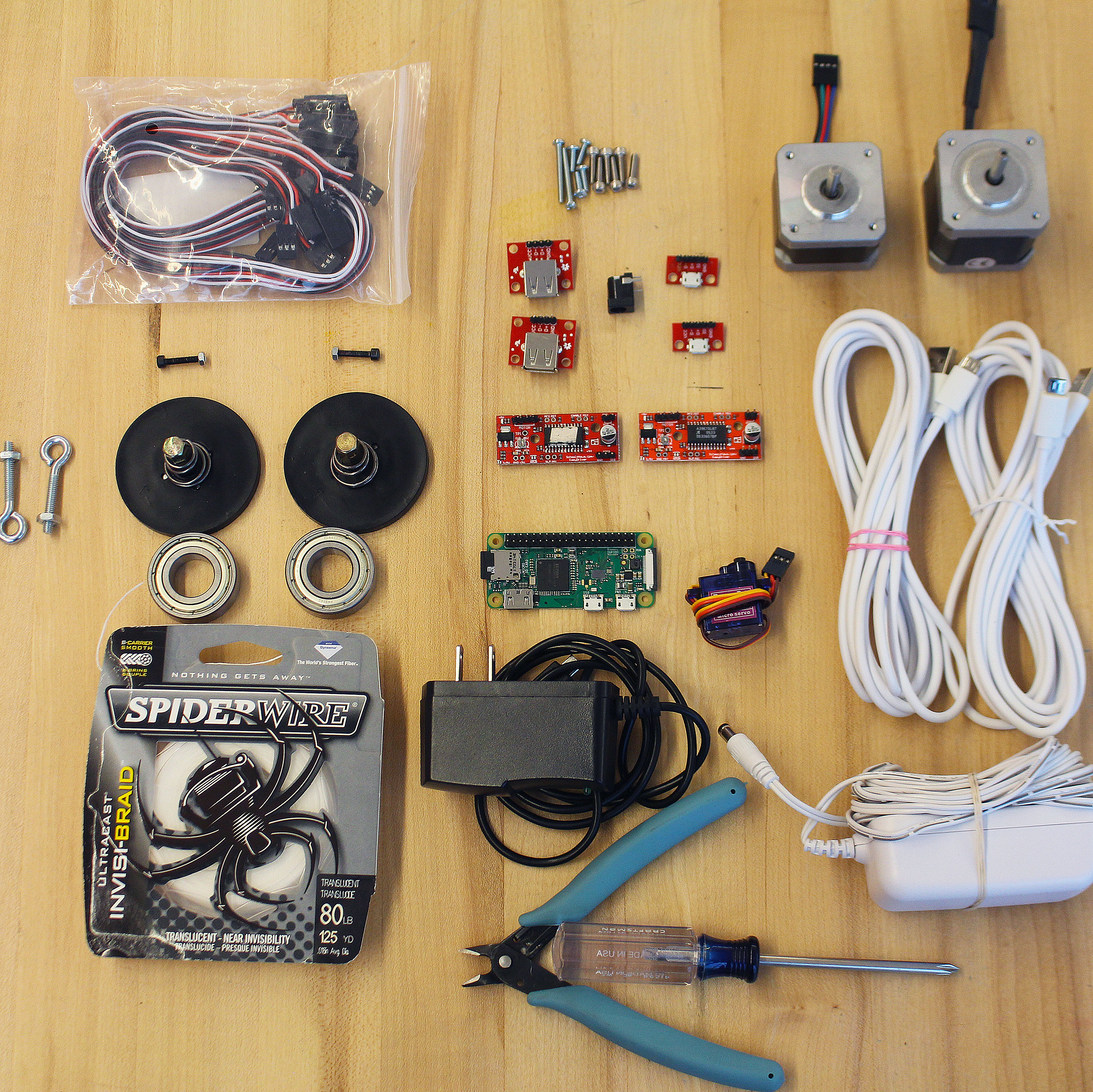
Hardware:
NEMA 17 Stepper Motors (x2)
Suction Cups with Quick Release - Harbor Freight item #62715 (x2)
Spiderwire 80-pound fishing line
Micro USB cable 10-ft. (x2)
Micro USB breakout (x2)
USB type A female breakout (x2)
Raspberry Pi Zero W (or another WiFi enabled Pi)
Micro SD card
EasyDriver Stepper Motor Driver V4.5 (x2)
SG92R Micro Servo
6003zz bearings (x2)
3-pin servo extensions (several)
2.1mm x 5.5mm barrel jack
12v 1a power adapter 2.1mm/5.5mm lead
USB Micro Power Adapter for Pi
Pololu Universal Mounting Hub for 5mm shaft, #4-40 holes (x2)
#8-32 x 1-5/8 in. Eye Bolts (x2)
8 screws for spools (#4-40 x ~½")
8 screws for motors (M3-.50 x 6mm metric machine screws)
1-2 small screws for gondola to secure pen/marker
Standard wire or jumper wires
markers
Measuring tape/stick
Tools:
Computer
Soldering Iron
Wire Strippers/Cutters
Optional:
Paper
Mounting Putty
USB Fan
Hot Glue
Paperclip
Header Pins
Breadboard/Perfboard
The drawbot github will have some links to specific sellers/items.
Stepper Motor and Suction Cup Assembly
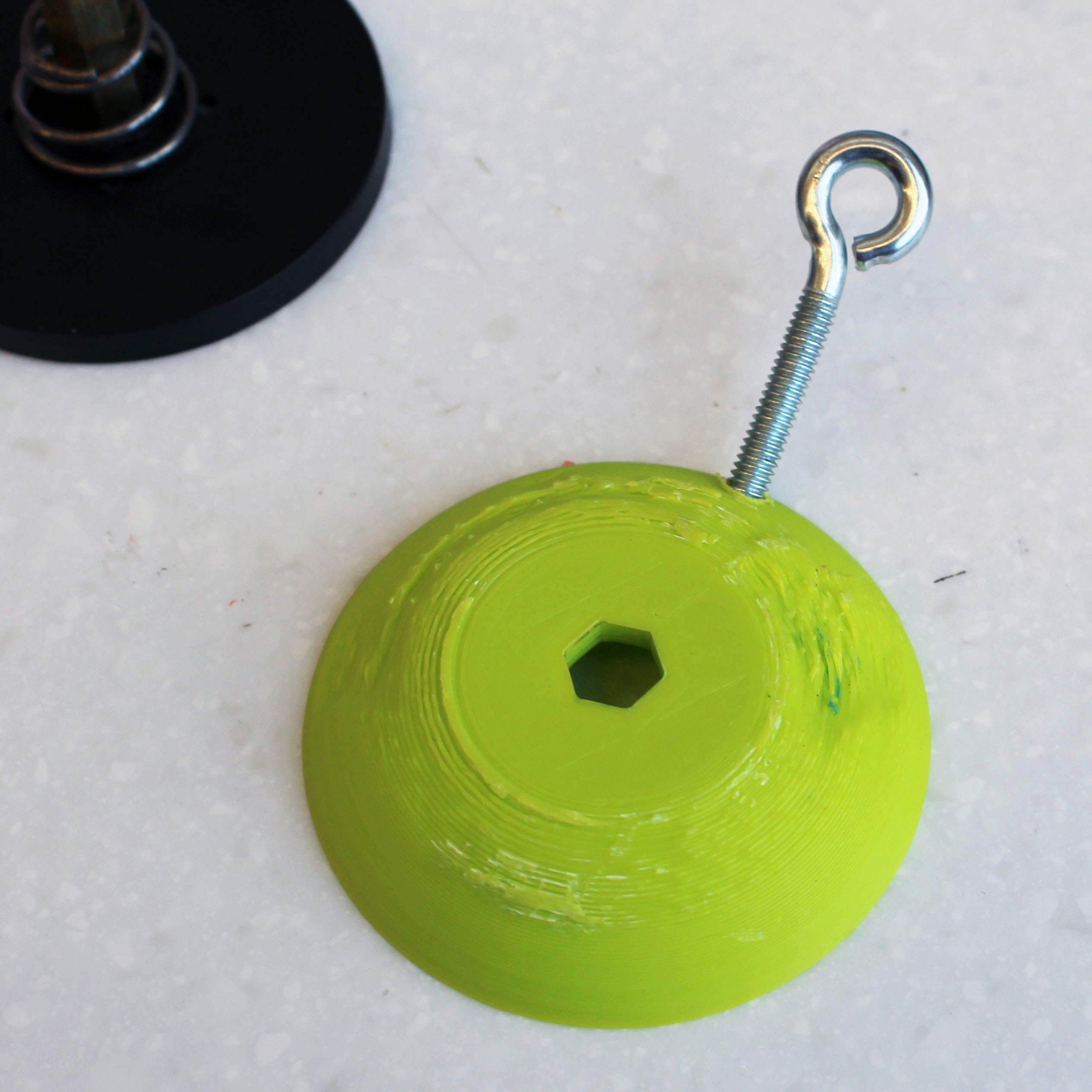
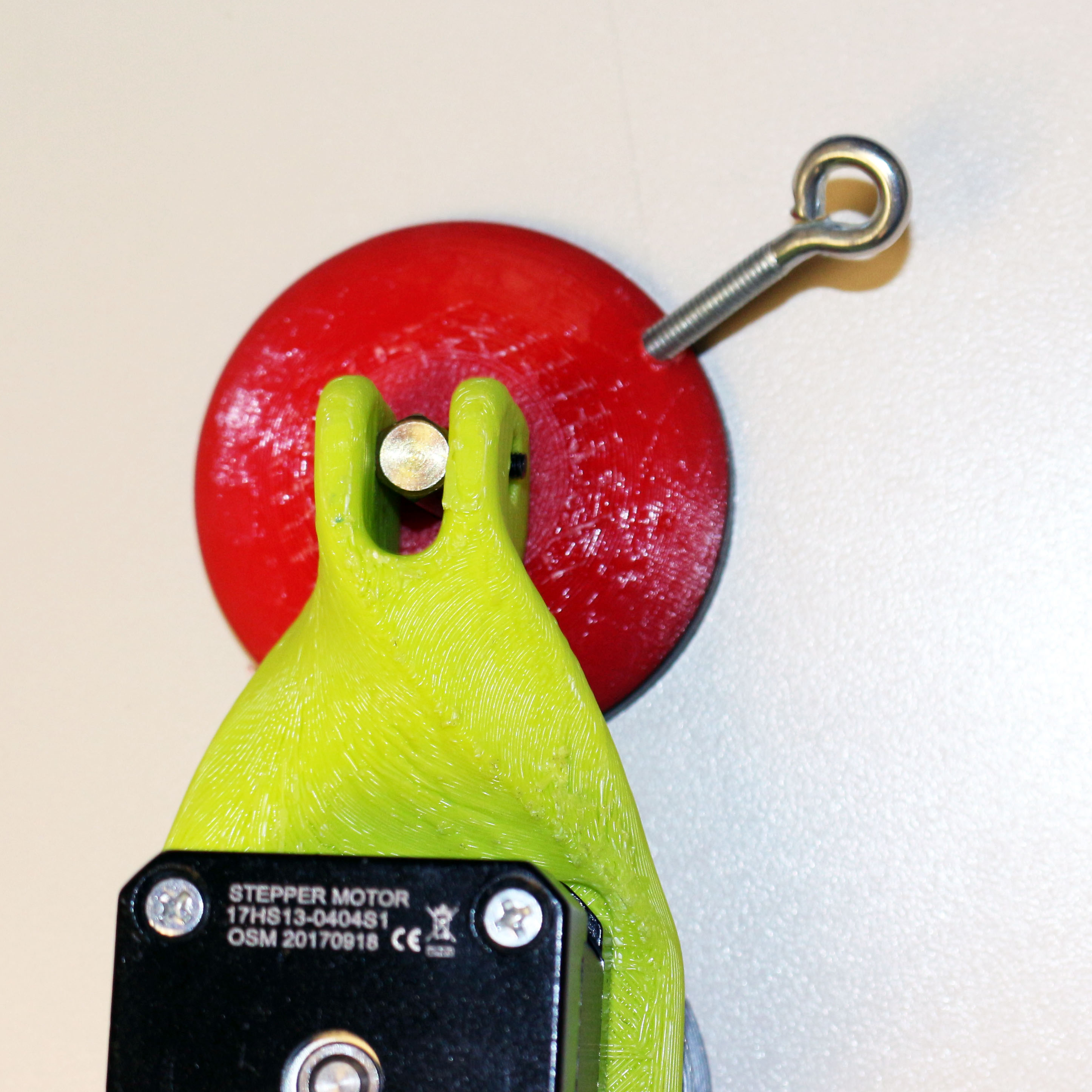
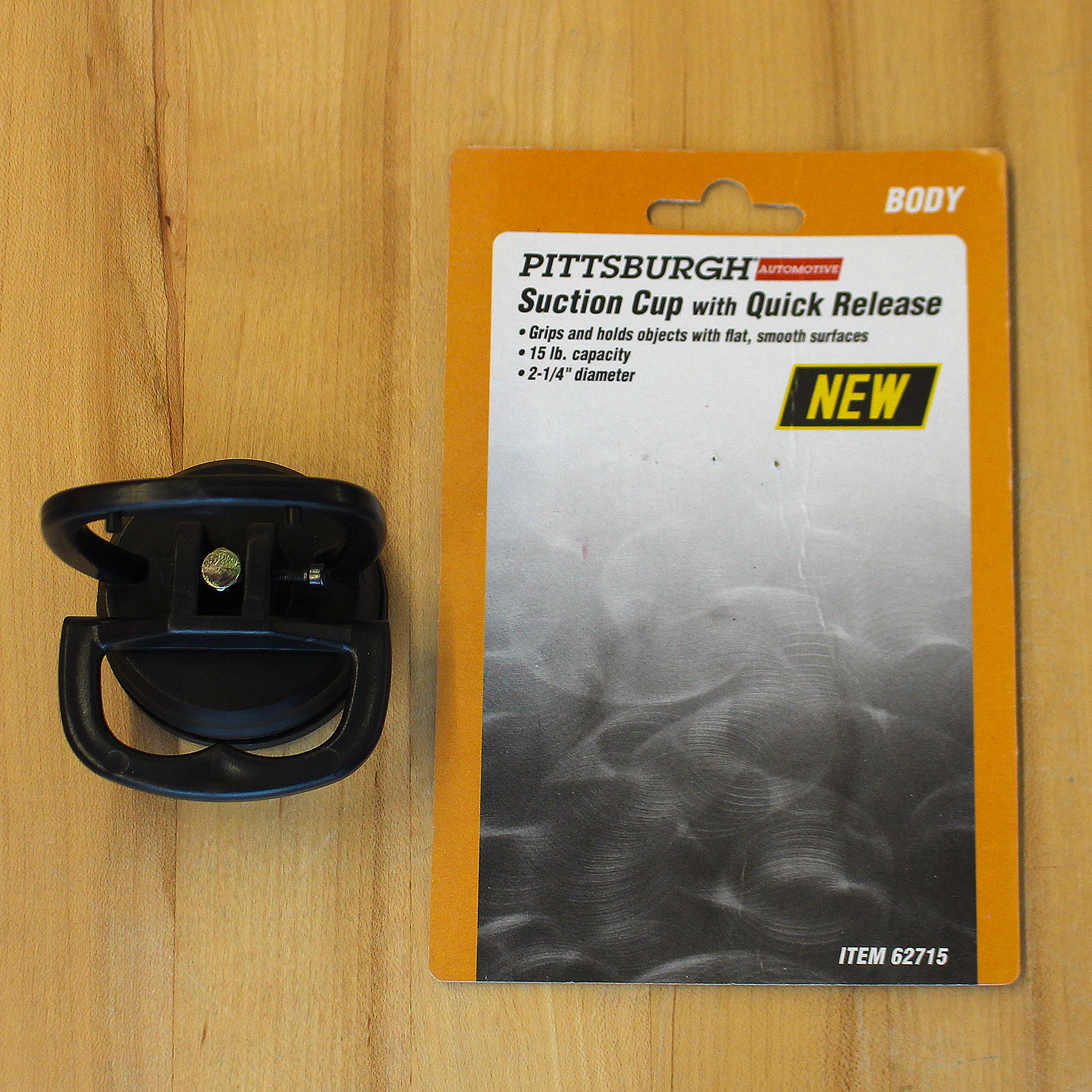
Parts needed this step:
3D printed:
2 motor mounts
2 spools
2 suction cup domes with 1/8" hole drilled -or- Suction Cup Dome with Hole
Notes: Printed in PLA
Hardware:
2 Stepper Motors
2 Suction Cups
2 Universal mounting hubs
2 Eye Bolts (#8-32 x 1-5/8 in.)
8 Screws for spools (#4-40 x ~½")
8 Screws for motors (M3-.50 x 6mm metric machine screws)
Fishing line
Notes: The suction cups need a long metal post to reach the motor mount.
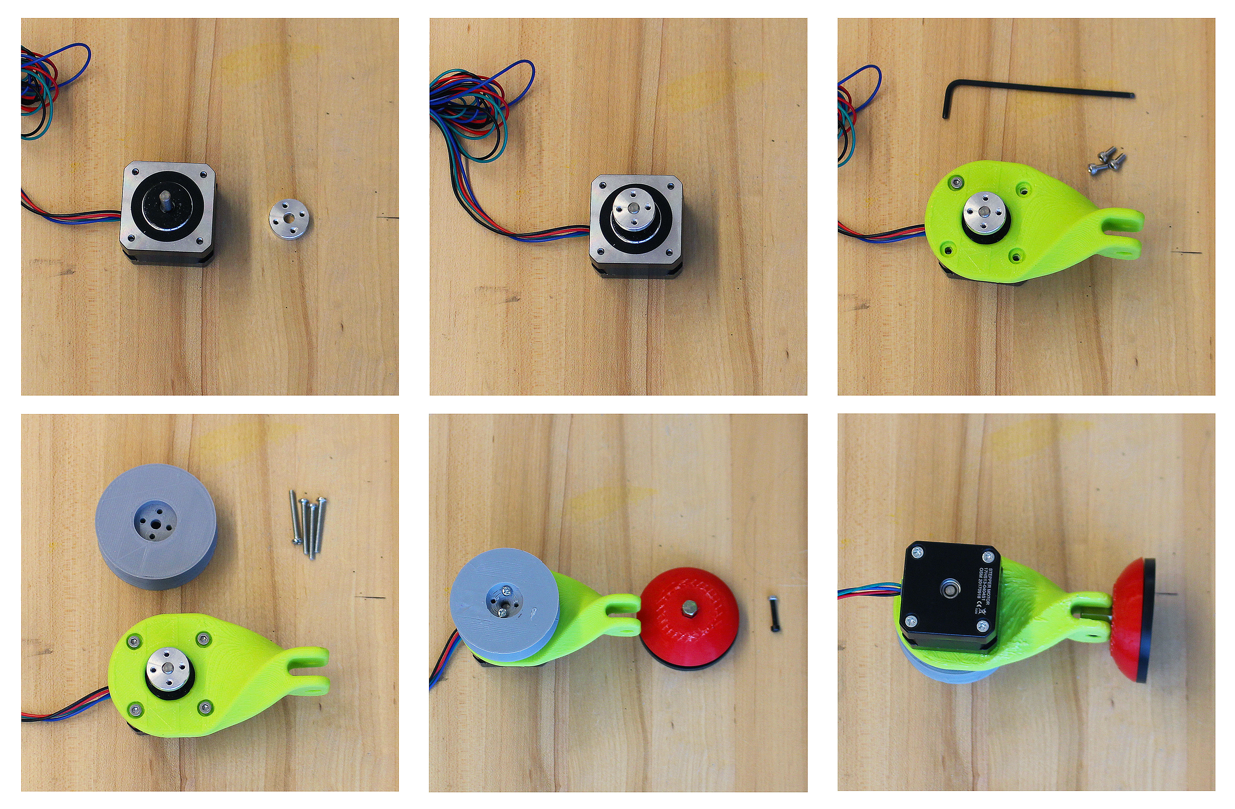
- First, attach the aluminum universal mounting hub to the stepper motor. Use the set screws included with the mounting hub and attach the hub close to the end of the stepper shaft.
- Next, attach the 3D printed twist motor mount to the stepper motor using four M3 screws. The twist motor mount will have an indentation to indicate which side to mount the motor.
- Now attach the 3D printed spool to the mounting hub with 4-40 screws.
- For the suction cup mounts you’ll need to disassemble your Harbor Freight suction cup. Keep the rubber suction cup, spring and metal post. Drill a ⅛” hole in the suction dome and thread in your eye bolts or use the Suction Cup Dome with Hole. Place the 3D printed dome over the rubber suction cup. Attach the motor mount by pushing it down on the suction dome so you can thread the screw through the metal post.
- Now do the same for the other motor mount.
- Spool fishing line on the spools.
Notes: Harbor Freight suction cups are a must, they have a taller metal post than other suction cups. The item number is 62715.
Pen Holder Gondola Assembly:
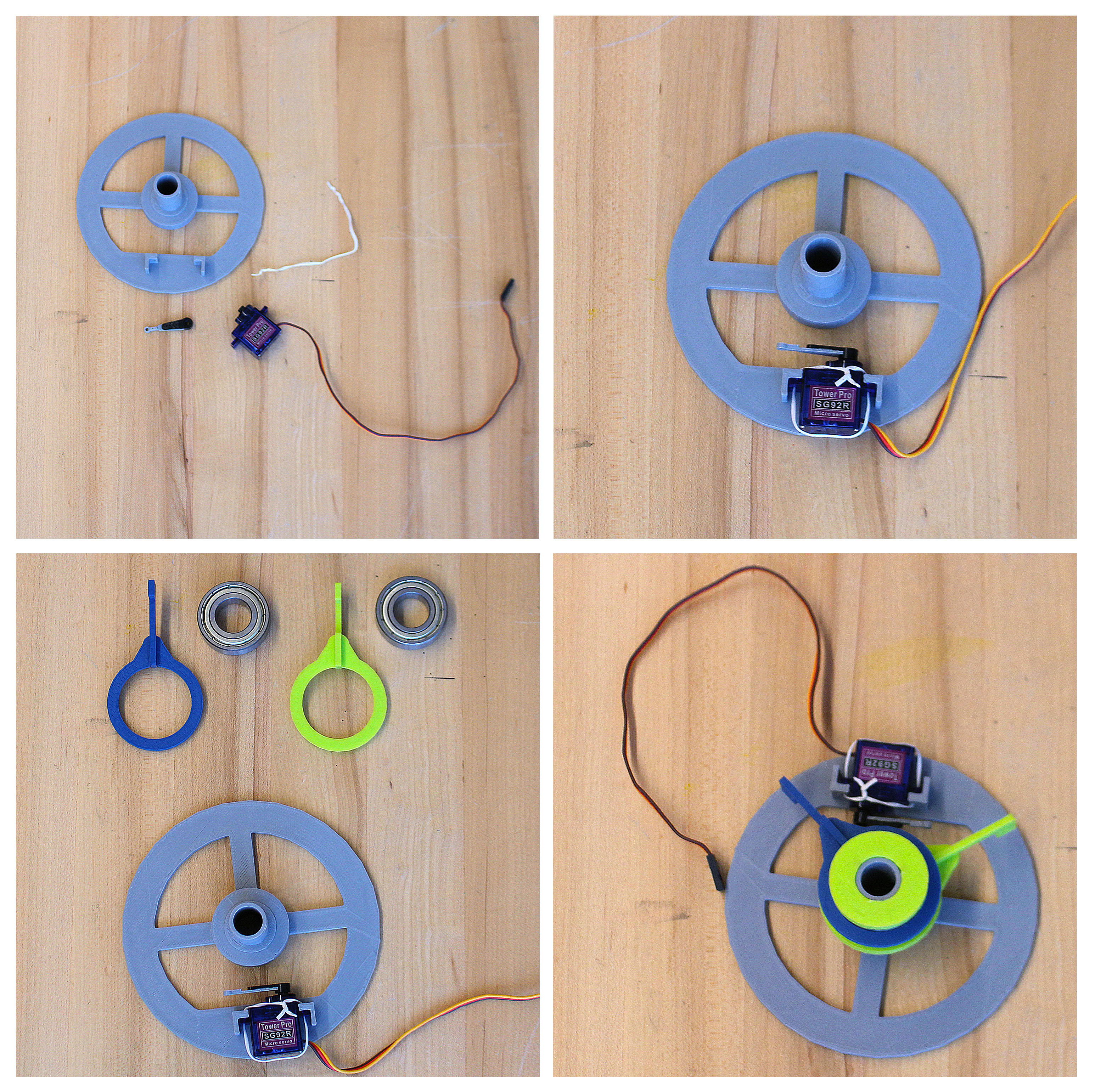
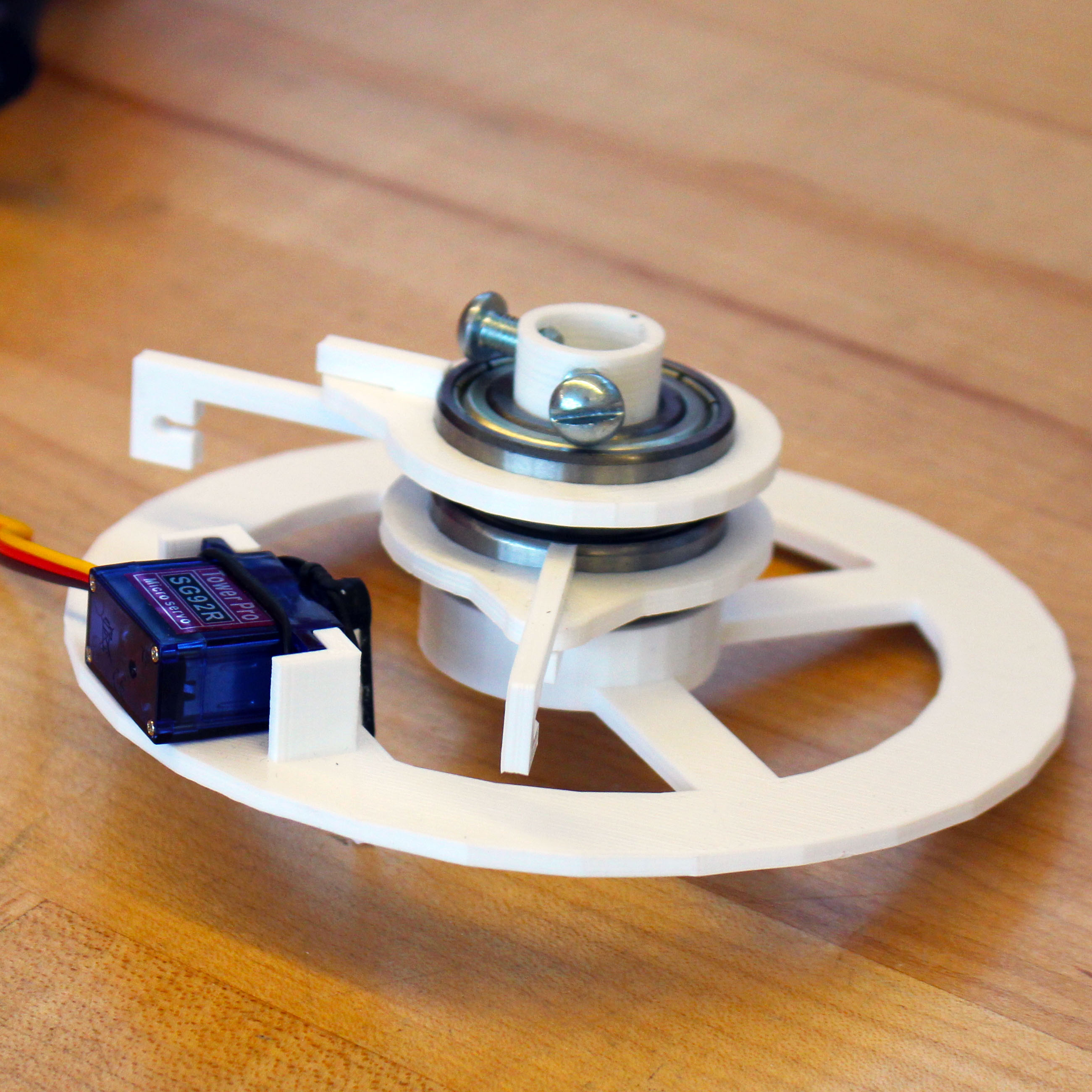
Parts needed this step:
3D Printed:
Polargraph Gondola
2 Bearing connector arms
2 Bearing connector rings
1 Gondola retainer
1 Servo extension
Hardware:
1 SG92R Servo motor
2 6003zz bearings
1 Twist tie
- Glue the 3D printed servo extension arm to one of the servo arms supplied with the servo. -Ours eventually fell off so we used a paperclip that we snipped in half and taped it to the servo arm.
- Use the ultra-handy twist tie to secure the servo to the gondola.
- Next slot the bearing connector rings to the bearing connector arms. Push the bearing through the bearing connector assembly, our 3D printed parts needed a bit of clean up with a blade to allow the bearing to push down into the bearing connector.
- Slide the bearings that now have the bearing conectors and arms on the gondola. The shaft on the 3D printed gondola needed to be sanded a good deal to allow the bearing to slide down.
- Last is the gondola retainer that will keep everything together, use screws to secure it to the gondola shaft - these also will secure your pen while drawing.
Software
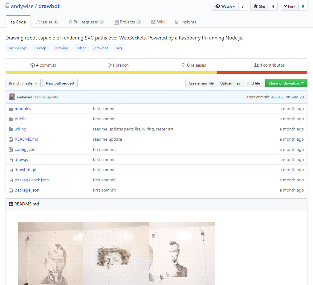
If you've never prepared a Raspberry Pi start by checking out our guide.
For this step I recommend referring to the Drawbot Github .
On the Pi you'll update and upgrade packages and install others:
Updates and upgrades:
sudo apt-get update
sudo apt-get upgrade
Install NPM and Git:
sudo apt-get install npm
sudo apt-get install git
Install Node.js:
sudo npm install -g n
sudo n stable
Upgrade NPM -and remove old apt-get version:
sudo npm install npm@latest -g
sudo apt-get remove npm
sudo reboot
Install pigpio C library:
sudo apt-get install pigpio *if you're using Raspbian Lite*
npm install pigpio
Install the Drawbot software:
git clone https://github.com/andywise/drawbot.git
cd drawbot
npm i
To start the Drawbot software:
cd/drawbot
npm start -or- sudo node draw.js
Access the Drawbot control interface
From another computer on the same network:
- From a Mac: Go to raspberrypi.local/control to access the Drawbot control interface.
- From a PC: input the ip address (ifconfig is the terminal command) and input your IP address/control ex: 10.167.5.58/control
From the Raspberry Pi:
- Open a browser. Go to 127.0.0.1/control to access the Drawbot control interface.
Connections. Wires. Everywhere.
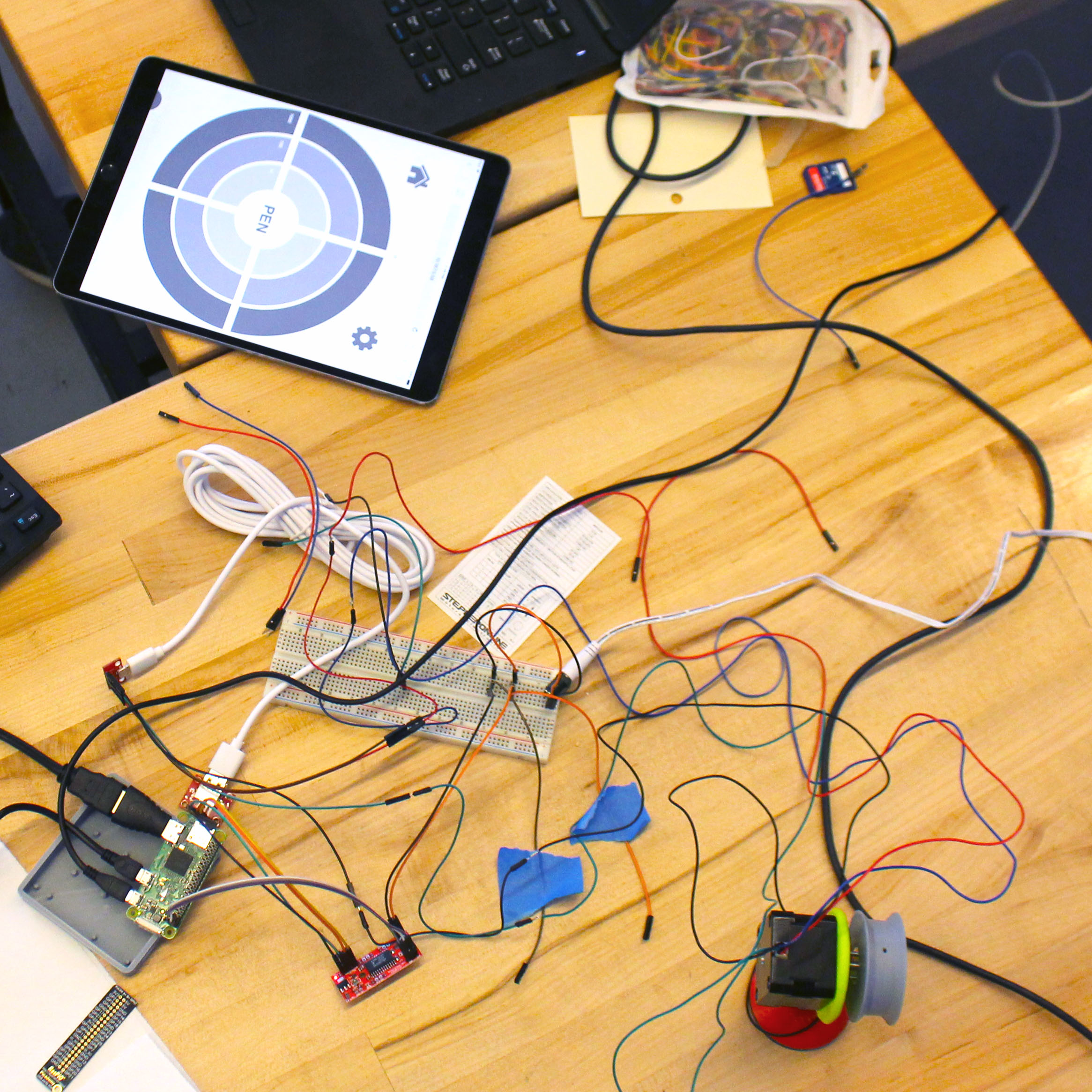
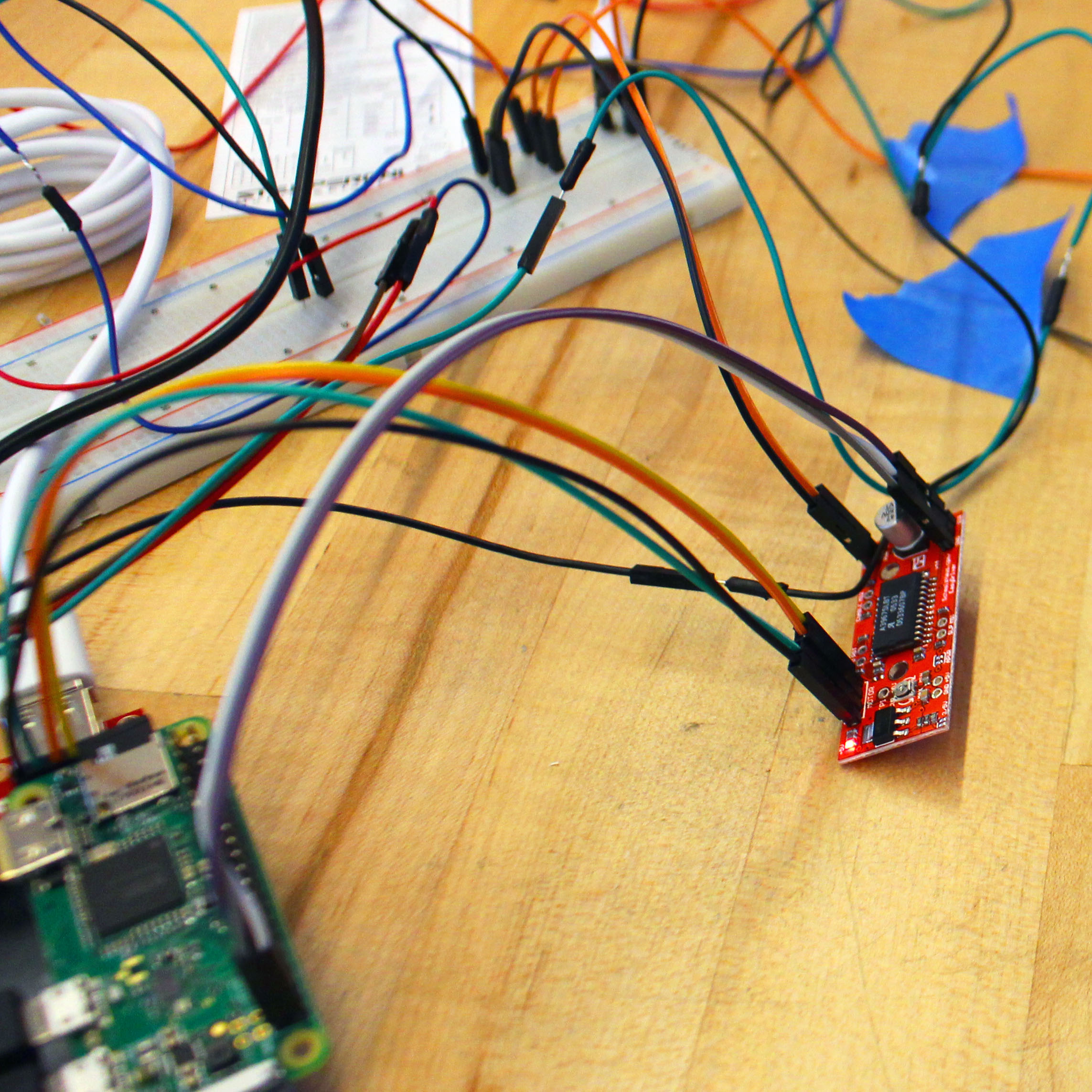
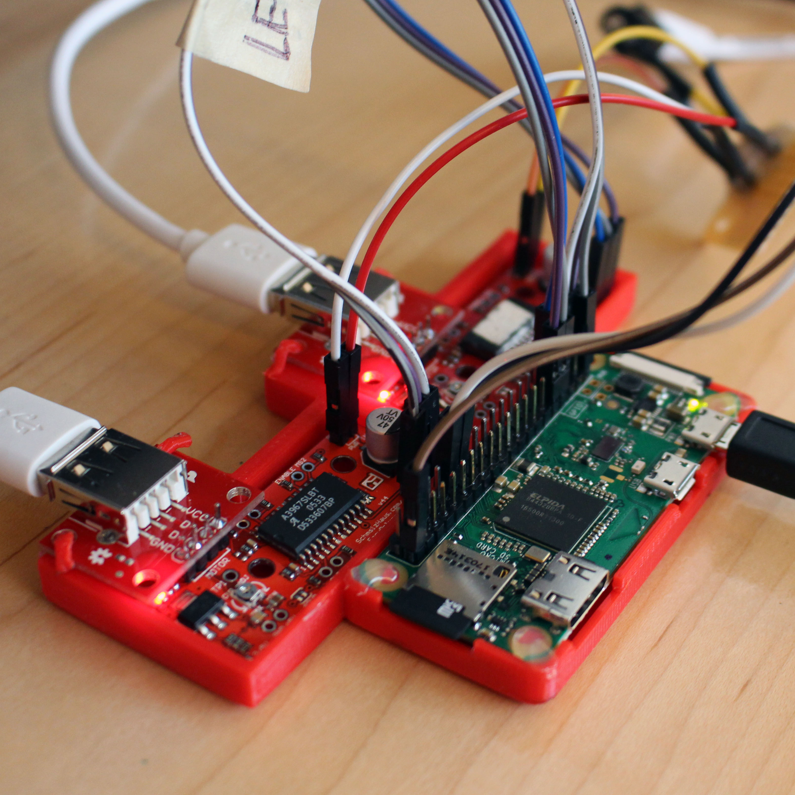
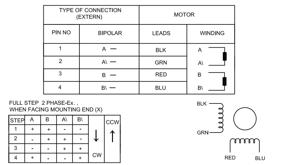
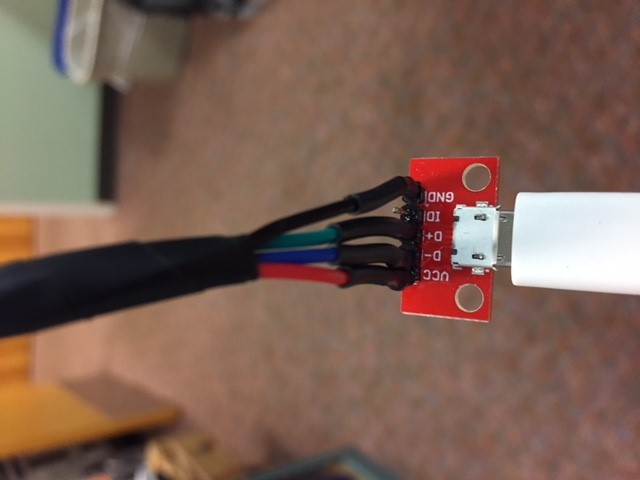
Parts needed this step:
Hardware:
USB A female breakout - 2
EasyDriver Stepper Motor Drivers - 2
Pi Zero or another WiFi enabled Pi
Stepper Motors - 2
Micro USB breakout - 2
Barrel Jack 2.1mm x 5.5mm
Other parts you might need :
Breadboard for testing connections
Header Pins
3D Printed Stepper + Pi mount
Perf or Proto board
Wiring the EasyDriver motor drivers to the Pi:
Left driver:
- GND → Pi GPIO 39
- DIR → Pi GPIO 38 (BCM 20)
- STE → Pi GPIO 40 (BCM 21)
Right driver:
- GND → Pi GPIO 34
- DIR → Pi GPIO 31 (BCM 6)
- STE → Pi GPIO 33 (BCM 13)
Wiring the Gondola Servo to the Pi:
- GND → Pi GPIO 14
- VCC → Pi GPIO 1 (3V3 Power)
- CNT → Pi GPIO 12 (BCM 18)
Notes: For testing to make sure the connections are correct it's recommended to breadboard first before soldering everything together.
- If your Pi and/or EasyDriver doesn't include header pins solder them on now.
- Connect the female USB breakouts to each EasyDriver using the motor section on the board. For this step hopefully, you have a datasheet or reference for your Stepper Motros. Make sure to keep the windings/coils together. The stepper here had pairs of Black & Green and Red & Blue. Here we kept "Winding A" to Ground and D+ on the USB breakout and "Winding B" to VCC and D- on the USB breakout.
- Use jumper wires to connect the servo motor to the Pi GPIO. -refer to the information above.
- Use jumper wires to connect the EasyDriver boards to the Pi GPIO. -refer to the information above
- Connect the stepper motor wires to the Micro USB breakout again making sure the pairs are matched correctly.
- The EasyDrivers need power. Connect the tip of the barrel jack to the "PWR IN" on the EasyDrivers and the sleeve of the barrel jack to the GND of the "PWR IN" on the EasyDrivers. We used a perfboard to split out our power and ground from the barrel jack to the EasyDrivers.
Testing and Drawing!
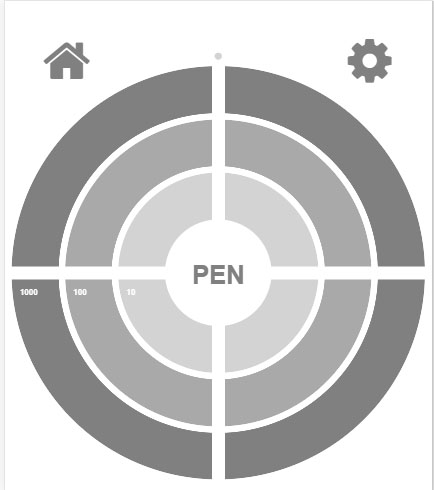
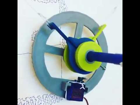
Once your Pi, EasyDrivers and USB breakouts are connected either via breadboard or if you jumped right in by solder, it's time to test.
Setup and Testing
Start the Drawbot controller software on the Pi. est the easier motor to control, the servo. Click the Pen button in the middle of the controller bulls-eye and hopefully the servo arm will rotate 90°. Use this test to make sure the servo arm is oriented correctly to lift the pen off the surface. This will also let you know if you're connected to the Pi and Drawbot controller software.
Next is the stepper motor. It's easier to start with one at a time. With a stepper motor connected click a coordinate on the Drawbot controller bulls-eye. The stepper should move smoothly. If the stepper stutters make sure the wiring is correct and the pairs are matched. Test the other stepper.
With the steppers disconnected find a nice flat, smooth surface and mount the steppers making sure they are level to each other. Extend some of the fishing line from each spool and connect it to the bearing arms on the gondola. Reconnect the steppers. Use the Drawbot controller to move the gondola. When clicking the upper right on the the bulls-eye the gondola should move to the upper right, if not adjust the config file. If the gondola moves opposite of what it should turn on mirroring in the configuration file on the Pi.
Measuring
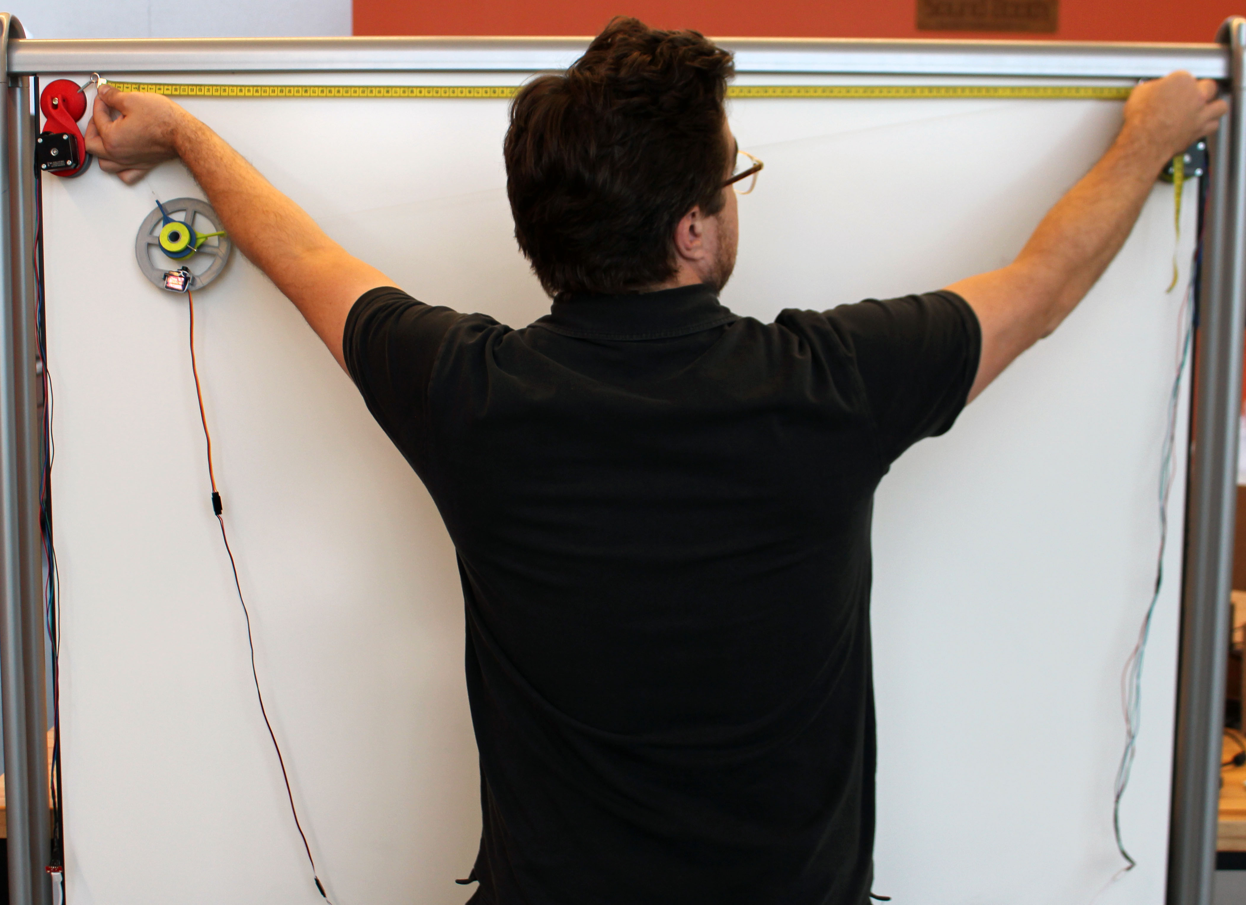
Almost there. Next is measuring. We've found a small retractable measuring tape handy, all measurements will be in millimeters.
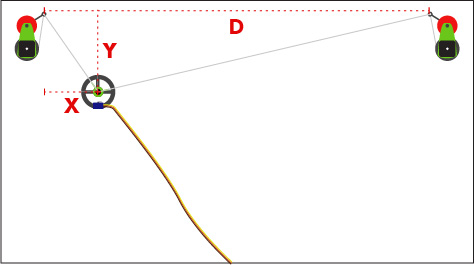
Click the settings icon in the Drawbot controller and there will be three values that are needed, "D", "X" and "Y". See the image for an illustration of how to measure. The first value, "D" is the distance between the spools. The next values are essentially the home location of the gondola. The "X" value is the measurement from the left spool to the position of the pen in the gondola. The "Y" value is the distance from the spool down to the gondola. Input these into the settings of the Drawbot software. Setting the home in the upper left corner is recommended.
Drawing
Finally drawing!!
Once everything is measured as accurately as possible and the pen in the gondola is lifted off the surface and homed it's time to feed the Drawbot a SVG to draw. Simply drag a single path SVG onto the bulls-eye of the Drawbot software to start a drawing, I've included a calibration drawing for your robot drawing pleasure. Enjoy!