Double Button LED


This beginner-level project is designed to help walk you through the process of having two buttons that control two separate LED lights. The LEDs act as inputs on the breadboard, whereas the buttons act as an output. With the help of Arduino Web Editor, you can easily turn on and off the LEDs.
This project was designed to help beginner coders by building on some of the more basic steps when it comes to coding. When developing this project, I noticed that it was difficult to find help with a project similar to this. All of the other ones were much more complicated than what I am capable of!
Sources:
Pushbutton (Digital Input). Tinkercad. (2021). https://www.tinkercad.com/things/8x3pCeFvMcf-pushbutton-digital-input/editel?lessonid=EJ04BAKJFSIZYJU&projectid=OMOZACHJ9IR8LRE&collectionid=OMOZACHJ9IR8LRE#/lesson-viewer.
Supplies
Arduino Uno
Breadboard
Buttons (2)
LED (2)
resistors (4)
Jumper Wires (10)
Gather Materials
.png)
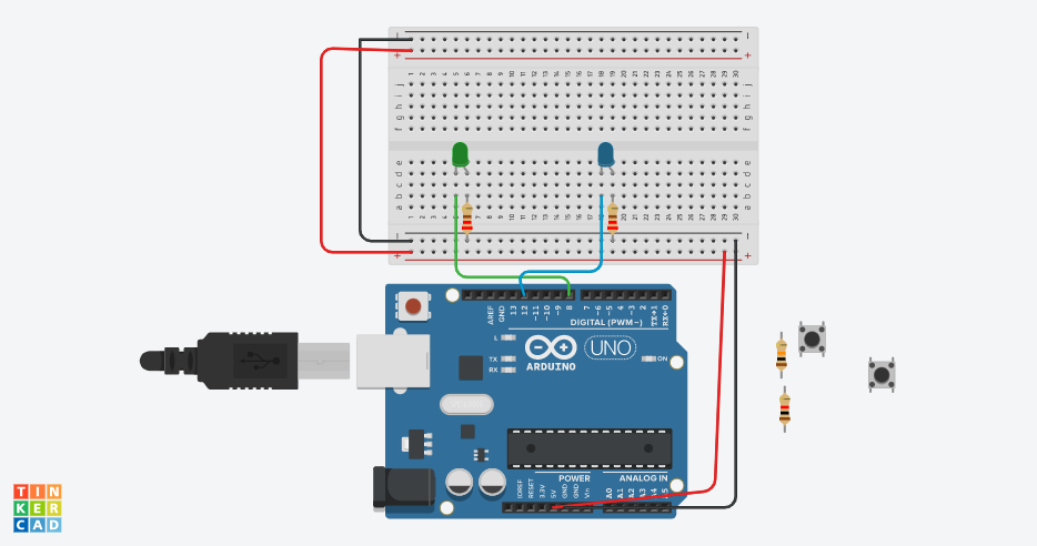
Identify the pushbuttons, LEDs, resistors, wires, Arduino, and breadboard.
Power Supply
 (1).png)
Connect breadboard power (+) and ground (-) rails to Arduino 5V and ground (GND).
Extend the Rails
 (2).png)
Extend the power and the ground rails on the respective buses on the opposite sides of the breadboard, by creating one wire between the power buses and one wire between the ground buses.
Add the LEDs, and Resistors
 (3).png)
Plug one LED into two different breadboard rows so the cathode (shorter, negative leg) connects to one leg of a 220-ohm resistor. Connect the other resistor leg to the ground.
Repeat with the other LED.
Wire the LEDs
 (8).png)
Wire the first LED anode (positive, longer leg) to Arduino pin 8.
Wire the second LED anode (positive, longer leg) to Arduino pin 12.
Add the Pushbuttons
 (9).png)
Add one pushbutton to the center of the breadboard and place it across the center column break, so that the legs are plugged into four different breadboard rows (two on each side of the break).
Repeat with the second push button. Make sure that the first push-button is in between the two LEDs.
Power the Pushbuttons
 (5).png)
Using one wire, connect the first button to power, on the opposite side of the breadboard, not the same side as the resistors.
Repeat with another wire and button number 2.
Connecting the Buttons
 (6).png)
Connect the diagonally opposite leg of the first button to Arduino pin 2. This is the input.
Connect the diagonally opposite leg of the second button to Arduino pin 4. This is the input.
Resistors
 (7).png)
Add a high-value resistor to the same diagonally opposite button leg and connect it to ground.
Repeat with another resistor and the second button leg.
Code It
Wire the Arduino to match the pictures. Then follow the link to the Arduino Web editor for the code.
First, the BUTTONstate needs to be declared at 0 for both of the events. Next pinMode is used to clarify and declare with pins that are being used, and what they are used for. In this case, pins 2 and 4 are used as an input or the buttons, and pins 8 and 12 are being used as an output or the LEDs.
Next is the void loop () here is where were declare what is going to happen. DigitalRead is used to see what is going on with the pins, then digitalWrite is used to change what is happening. The variables HIGH and LOW are used to either turn on (HIGH) the LED or to turn off (LOW) the LED.