Doorbell Camera on Moto360 Using Nodemcu and Autoremote
by RuneP in Circuits > Arduino
8762 Views, 42 Favorites, 0 Comments
Doorbell Camera on Moto360 Using Nodemcu and Autoremote
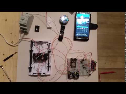
First off, I work as a carpenter and are by no means a good programmer or coder. Nor am i good with circuits and electronics. So there may be better ways to achieve this and all inputs are welcome.
I wanted to make something simple to be able to see whos at my door on my moto360 smartwatch.
I'm very interested in arduino stuff and Tasker for android so i chose that as my tools.
This instructable will not cover setting up ip camera as there are so many.
My setup is a HIKvision and i use a dynDDNS service to update my public ip.
Equipment
used:
Hikvision Camera mounted with Entry Door
Android Phone
Motorola 360 Smart watch
Apps needed:
Autoremote (paid or subscription (highly recomended))
If you use tasker i really recommend subscribing to autoapps as those are the best plugins and the developer is really active on google+ helping out.
Hardware used by me:
· NodeMCU
· 1 Capacitator
· 1 Rectifier
· 1 Stepdown module
· 1 reed switch
Breadboard, wires and momentary button for testing. (Optional)
Soldering Iron and Pcb copper board.
Setting Up Autoremote
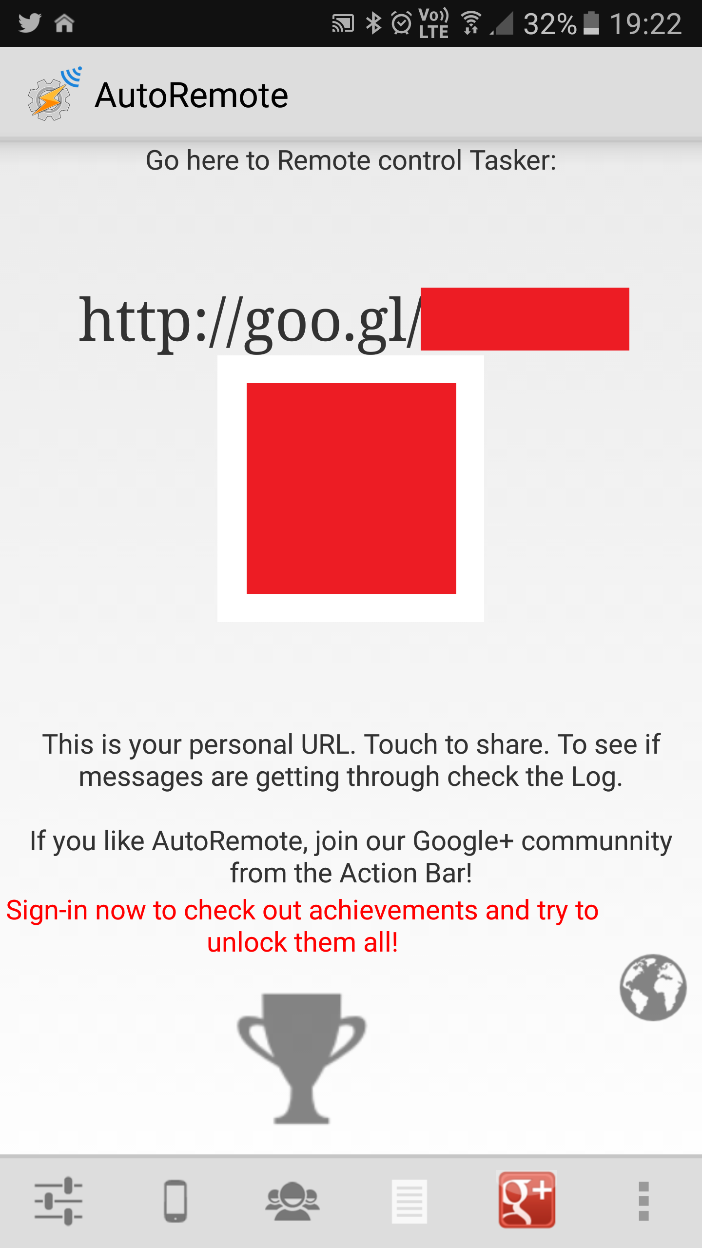
Open AutoRemote.You will see the shortadresse to your autoremote key.
Open that in a browser. You will then get http://autoremotejoaomgcd.appspot.com/?key=[this is where your key is gonna be]
Copy that key into the arduino code.
Nodemcu Code and Hookup
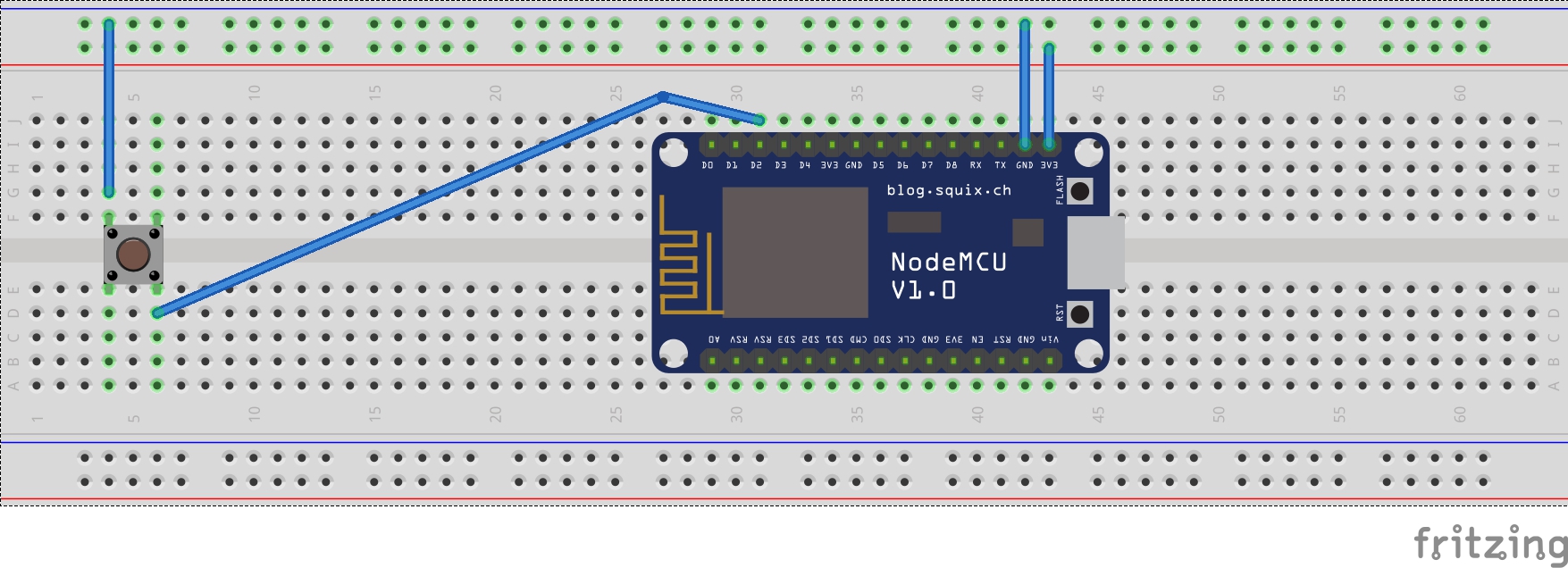
For testing berfore installation You'll need your breadboard a button and some wires.
Connect everything as shown in the picture.
Open Arduino IDE, make sure you have the correct card an com port.
Use the following code
make sure to insert your wifi SSID, password and autoremote key
--------------------- Arduino IDE Code start ---------------------
#include
const char* ssid = "{insert your ssid}"; //SSID Name
const char* password = “{insert password}"; //Wifi password
const char* host = "autoremotejoaomgcd.appspot.com"; // Autoremote URL
const char* key="{insert your key here}";
const int buttonPin = 4; // pin 4 is pin 2 on nodemcu
int buttonState = 1;
//WiFiServer server(80);
char* message="ArduinoStartet"; // (Sends a message about startup.) NO WHITESPACE ex message="Arduino Startet"
void setup() {
pinMode(buttonPin, INPUT_PULLUP); //Avoid using a resistor on the circuit
Serial.begin(115200); //For debugging
delay(10); //Small delay
// Connect to WiFi network
Serial.println();
Serial.println();
Serial.print("Connecting to ");
Serial.println(ssid);
WiFi.begin(ssid, password);
WiFi.mode(WIFI_STA); // Avoid setting ESP266 as an access point
while (WiFi.status() != WL_CONNECTED) {
delay(500);
Serial.print(".");
}
Serial.println("");
Serial.println("WiFi connected");
//delay(7000);
bell_rung();
}
void loop() {
buttonState=digitalRead(buttonPin);
if (buttonState ==0){
Serial.println("Knapp");
message="dingdong";
bell_rung(); // Remove this if you dont want the startup message
delay(4000); //Dont flood the server (4 s)
}
}
void bell_rung() {
Serial.println(message);
//// Connect to host (autoremote server) ////
WiFiClient client;
const int httpPort = 80;
client.connect(host, httpPort);
//// Get URL to send message ////
//// Times out after f 5 seconds ////
IPAddress ip;
ip = WiFi.localIP();
client.print(String("GET ") + "/sendmessage?key="+key+"&message=" + message +" HTTP/1.1\r\n" +
"Host: " + host + "\r\n" +
"Connection: close\r\n\r\n");
unsigned long timeout = millis();
while (client.available() == 0) {
if (millis() - timeout > 5000) {
client.stop();
return;
}
}
//// Read and store response from the host, can printed for debugging ////
while (client.available()) {
String line = client.readStringUntil('\r');
Serial.println(line);
}
}
--------------------- Arduino IDE code end -- ---------------------
power up and go into autoremote Logs to see if the message arduinostartet came through.
If so, press the button to see if a toast dingdong appears on screen.
Setting Up Tinycam Monitor Pro
This will differ depending on what camera you have so this step you'll have do do on your own
Add Profile and Task in Tasker
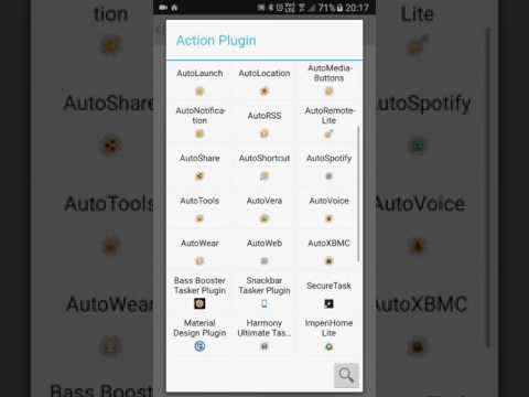
Follow the steps in this video to setup your tasker profile
Mount Inside Doorbell
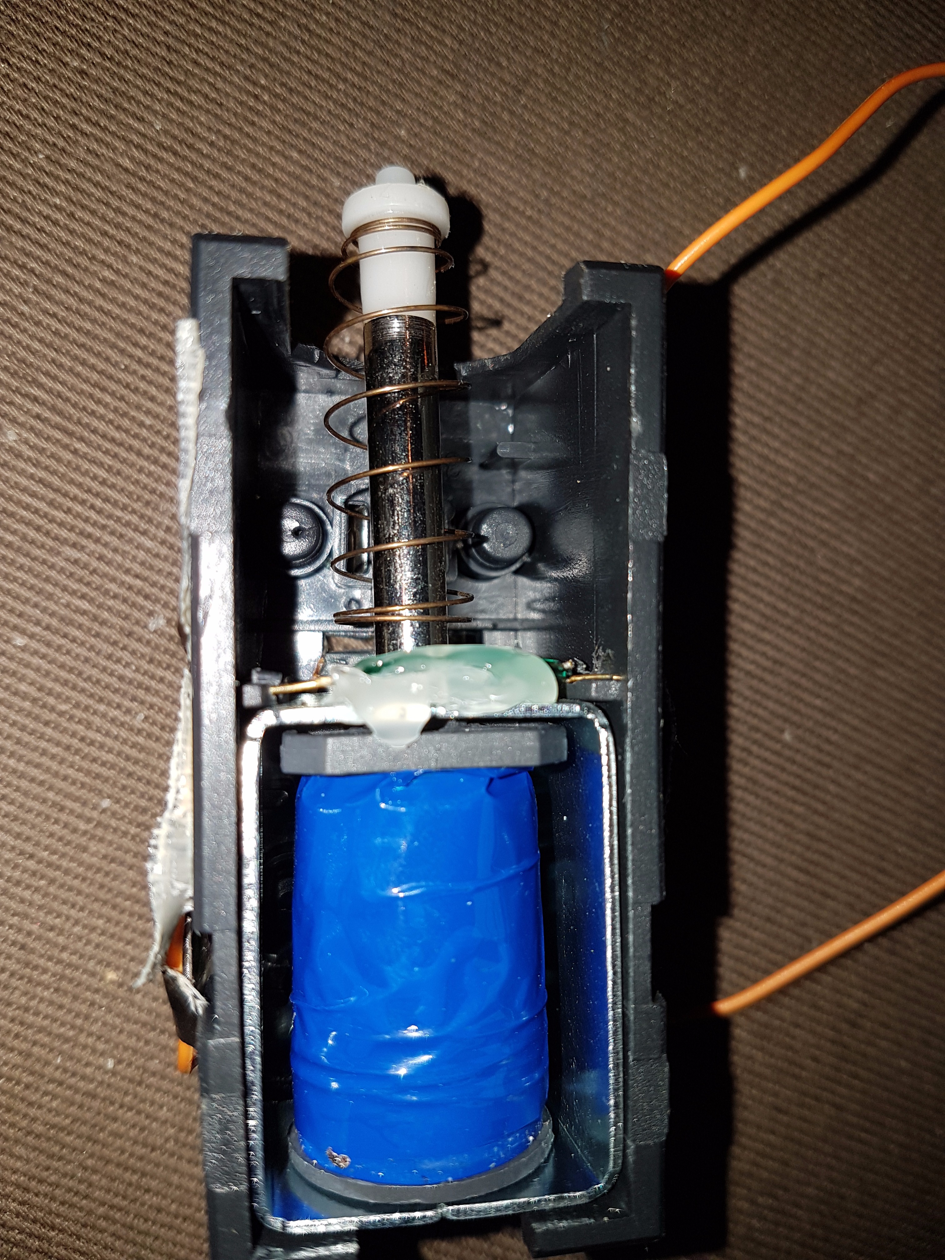
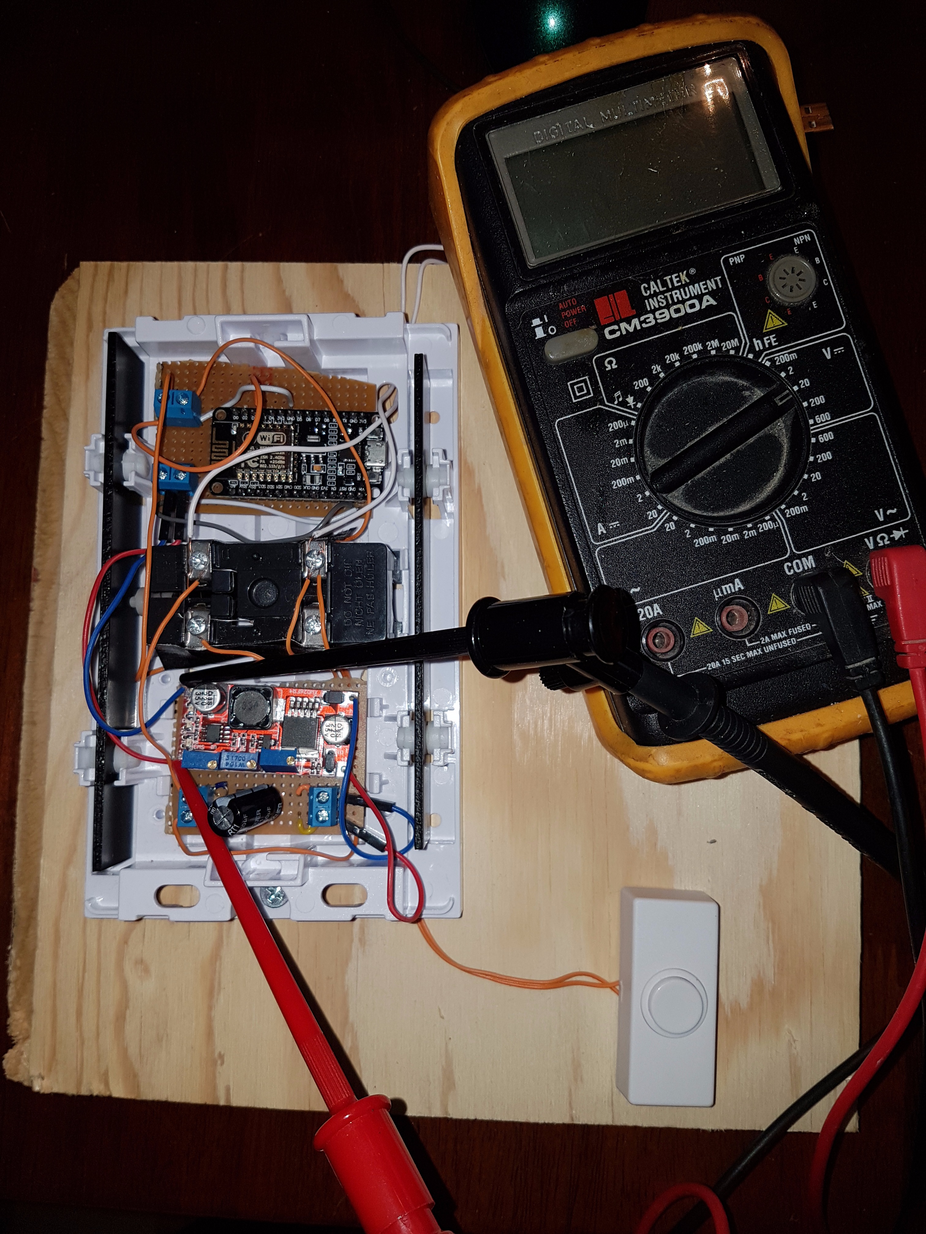
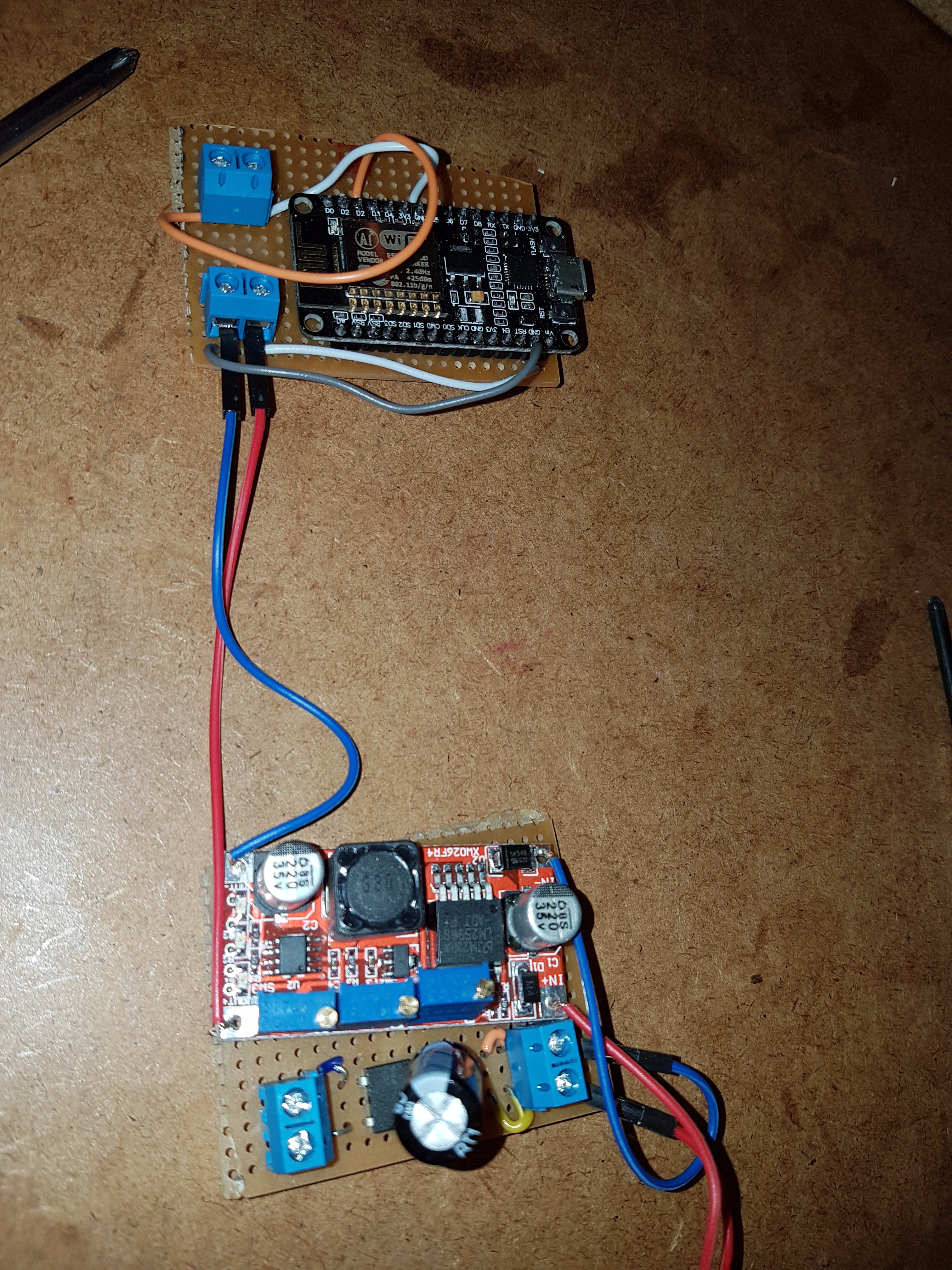
I drilled a small hole in the back of the solenoid and put the reed switch through.
So when someoe push the ring button the solenoid triggers the reed switch. Just connect the reed switch as the button was connected.
I used a rectifier from the 12 ac to get dc. and then the stepdown module to get 5vdc. Use a voltmeter on the output from the module and adjust until you have 5V. Then you can power the nodemcu directly from the doorbell
Mount the doorbell on your wall and it should work like the first video