Door Alarm With ATTiny
by Sky_Rider in Circuits > Microcontrollers
2808 Views, 4 Favorites, 0 Comments
Door Alarm With ATTiny
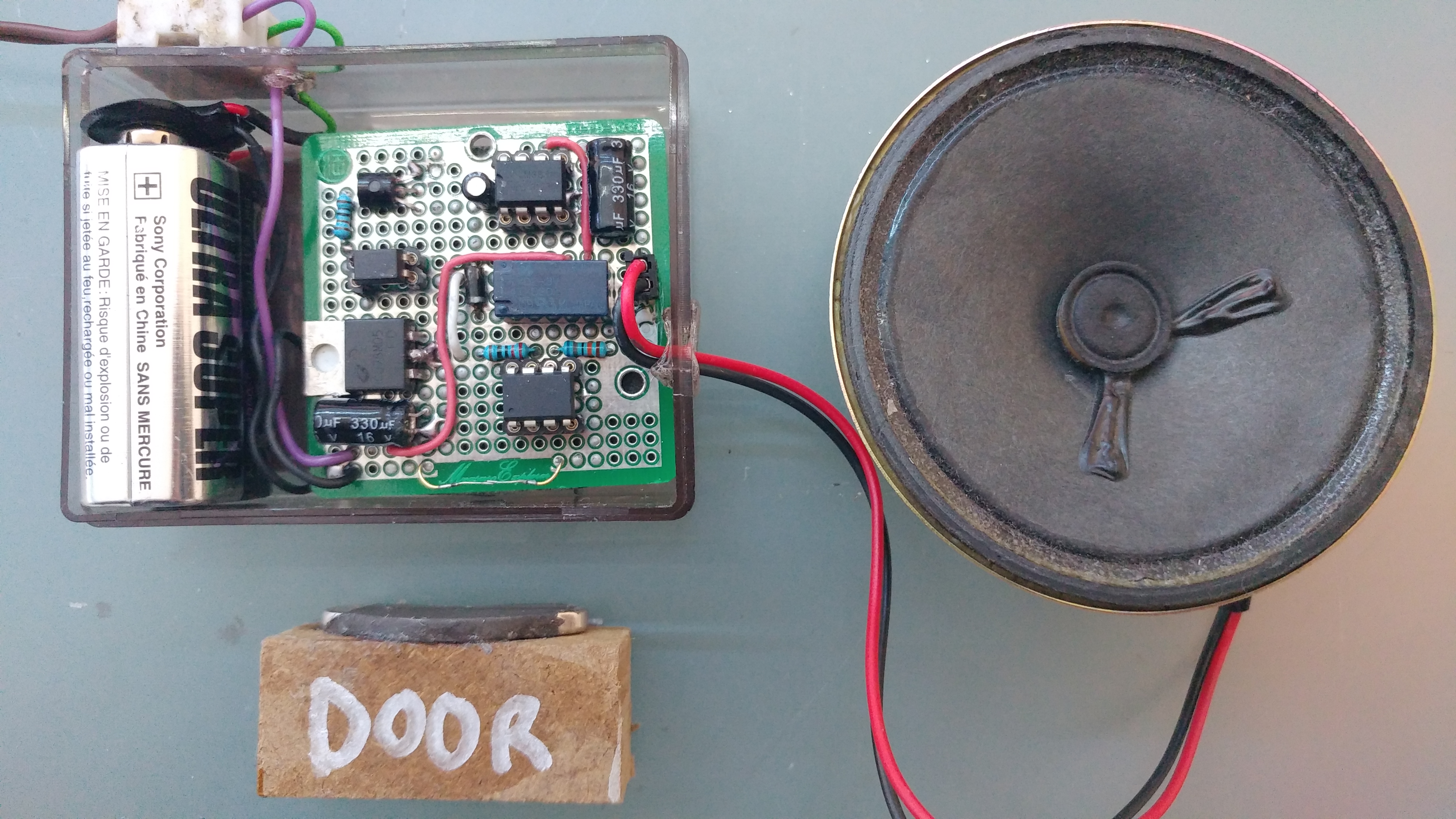
Hi everyone, in this page i'm going to show you how i made a simple door alarm that is compact,loud and battery powered.
Components
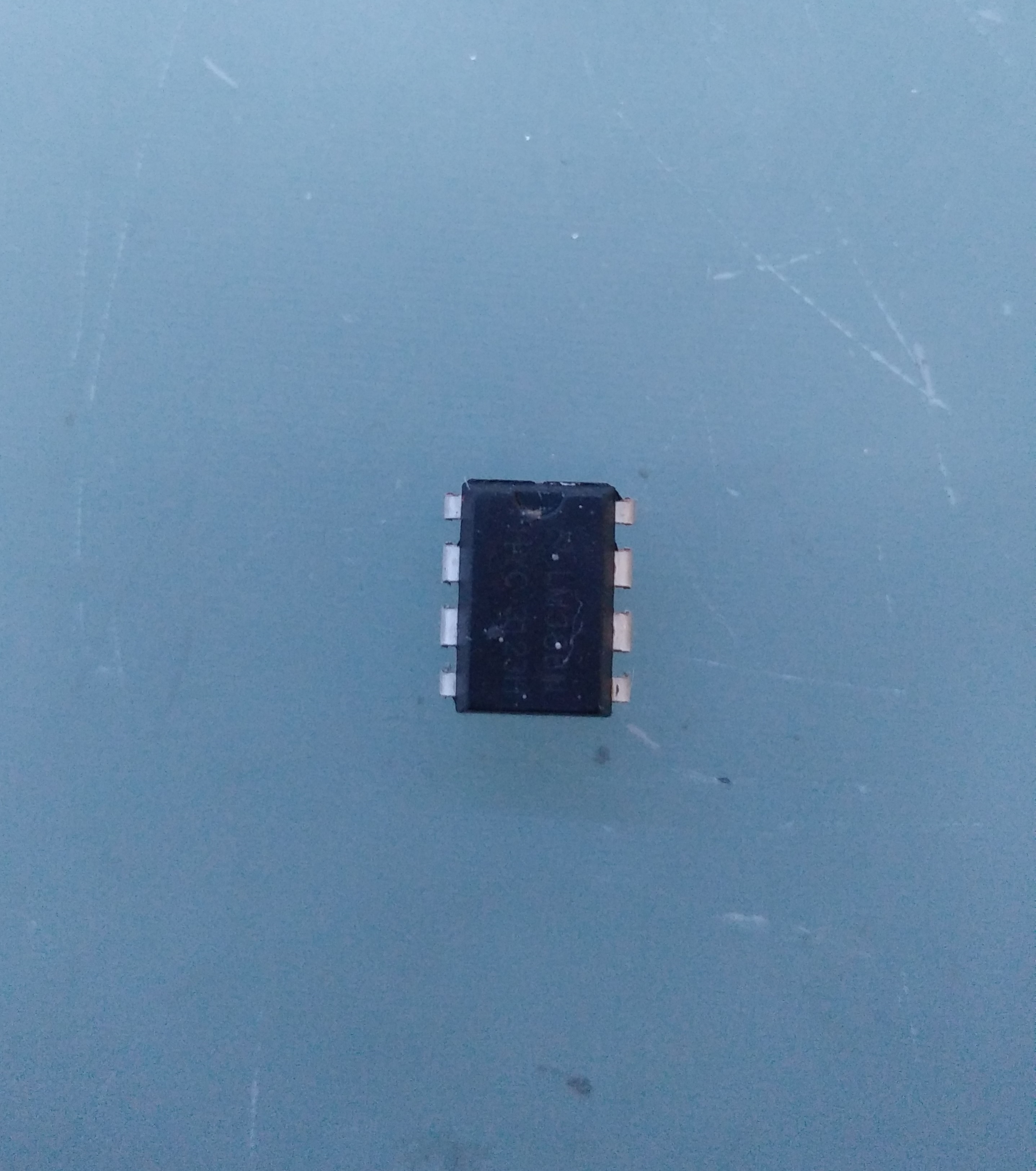
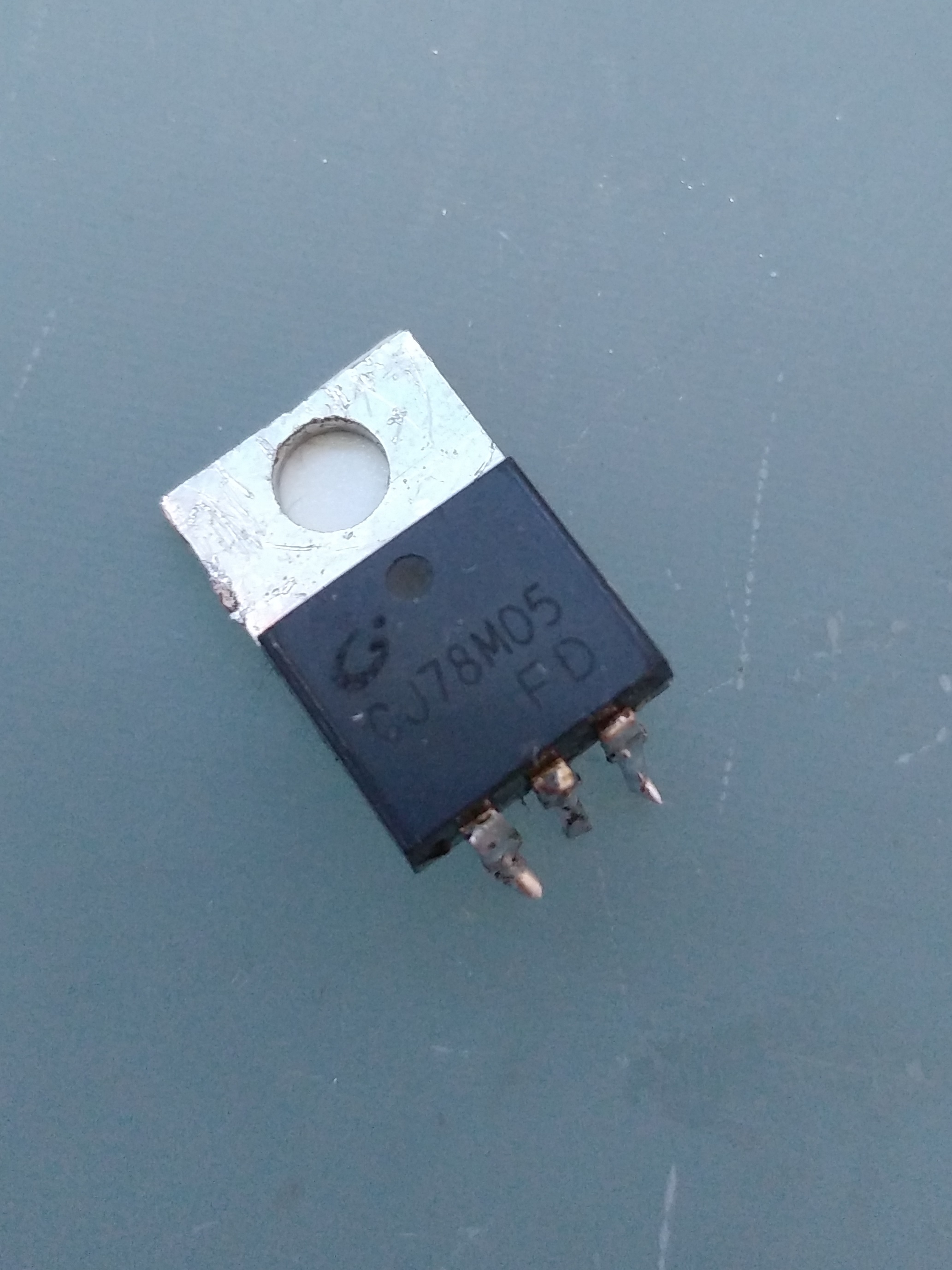
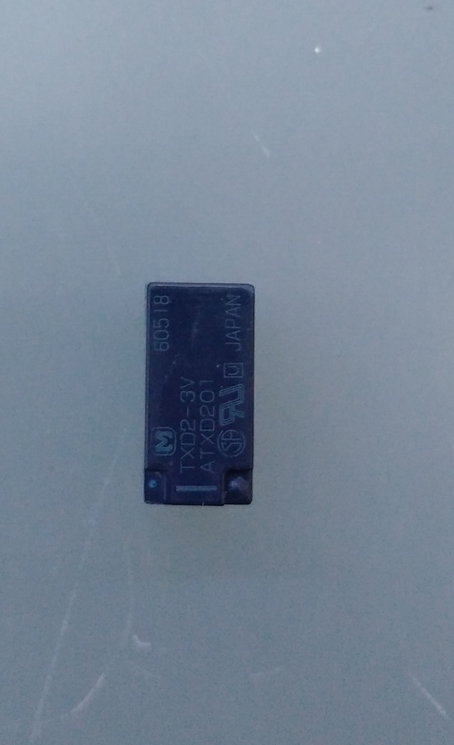
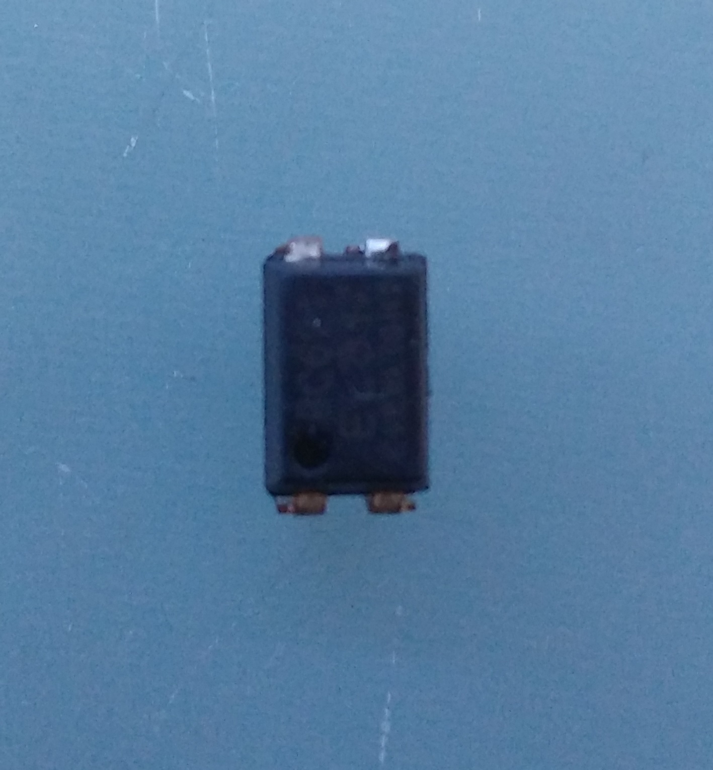
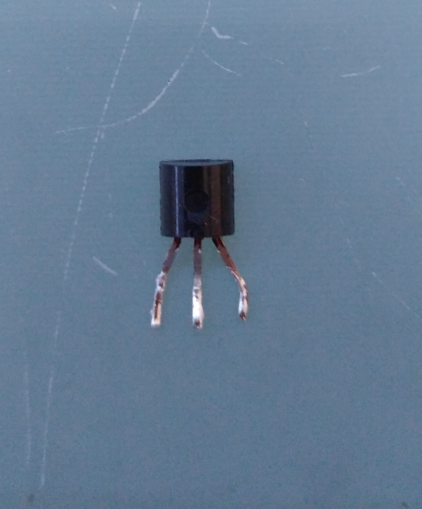
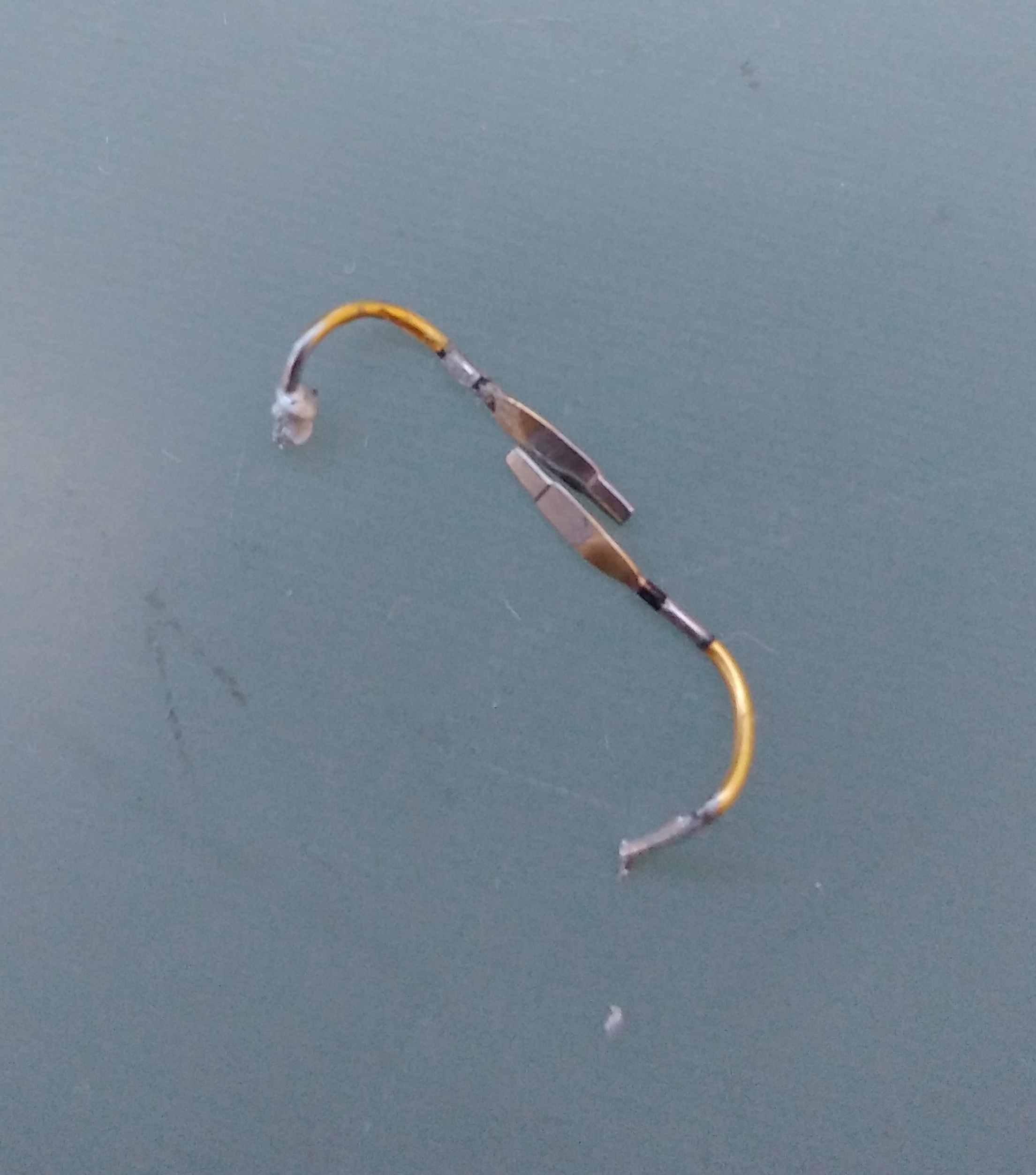
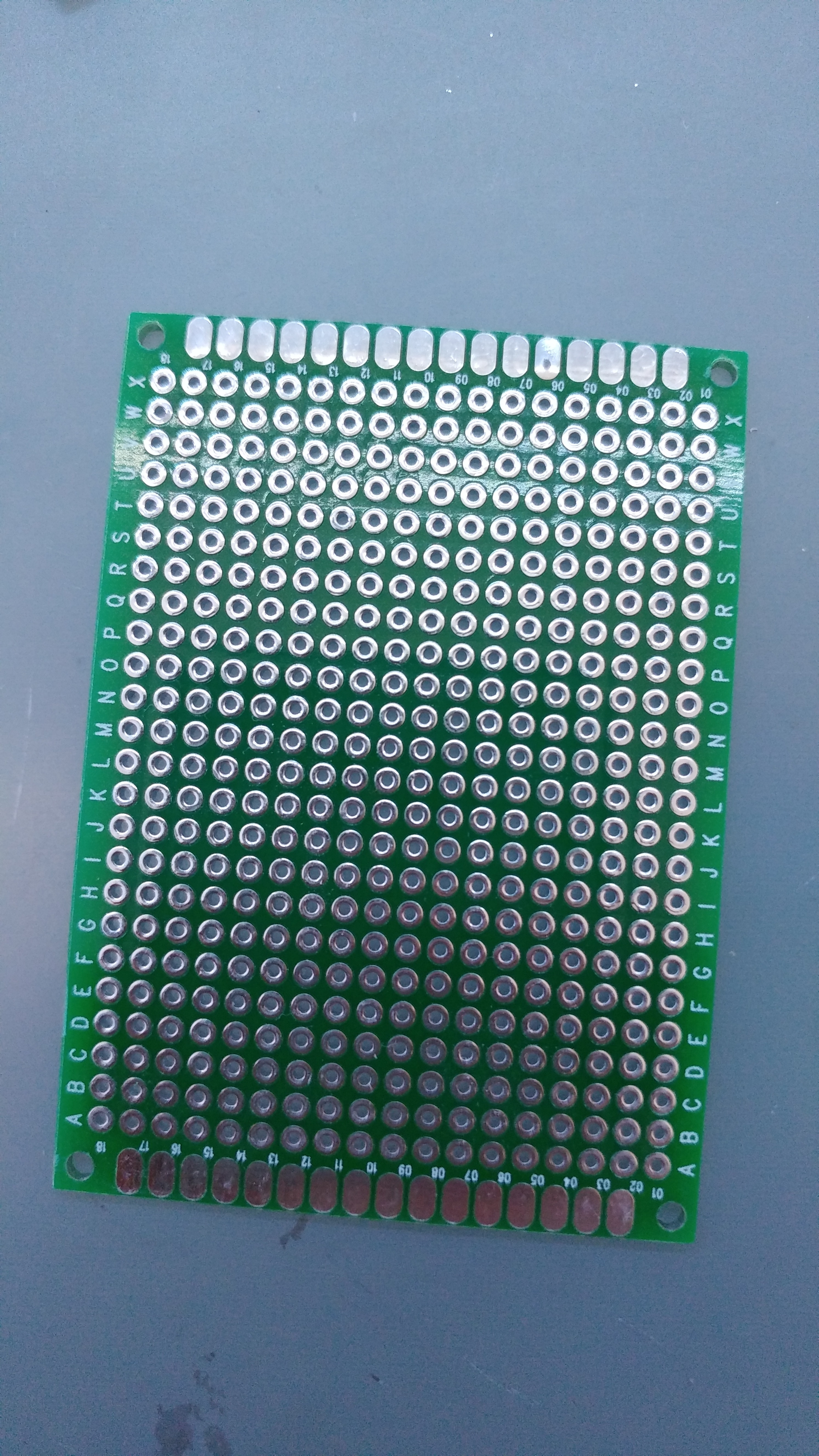
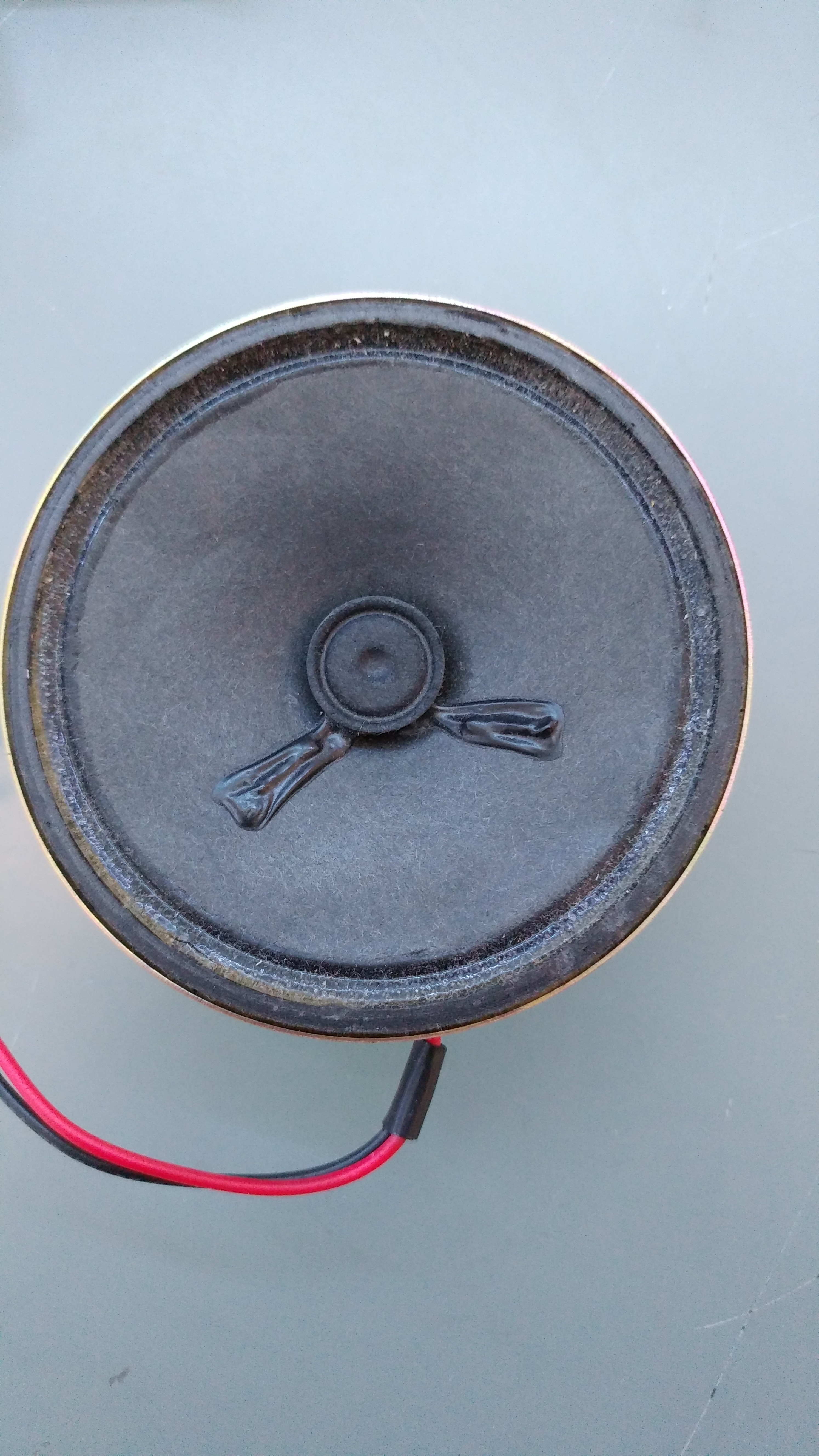
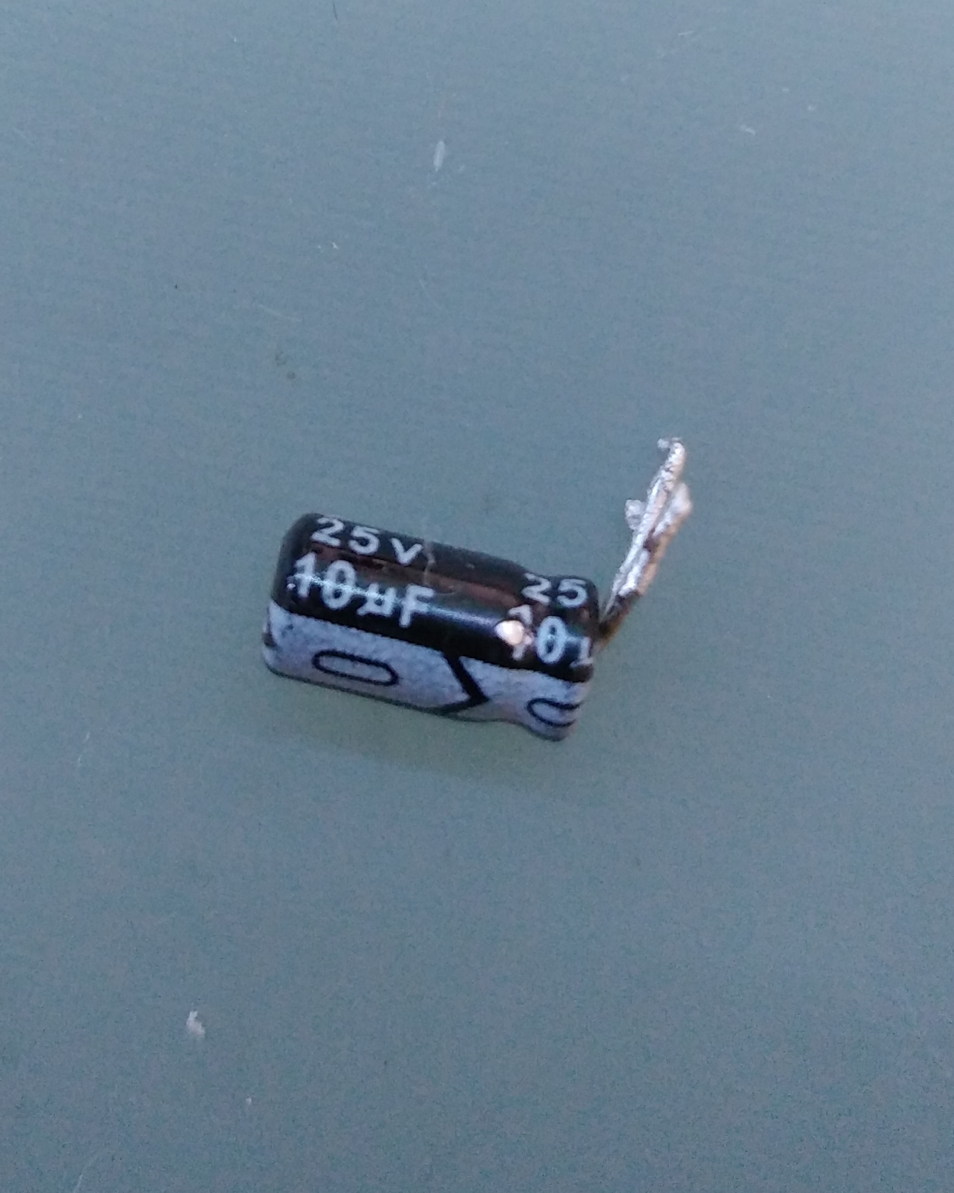
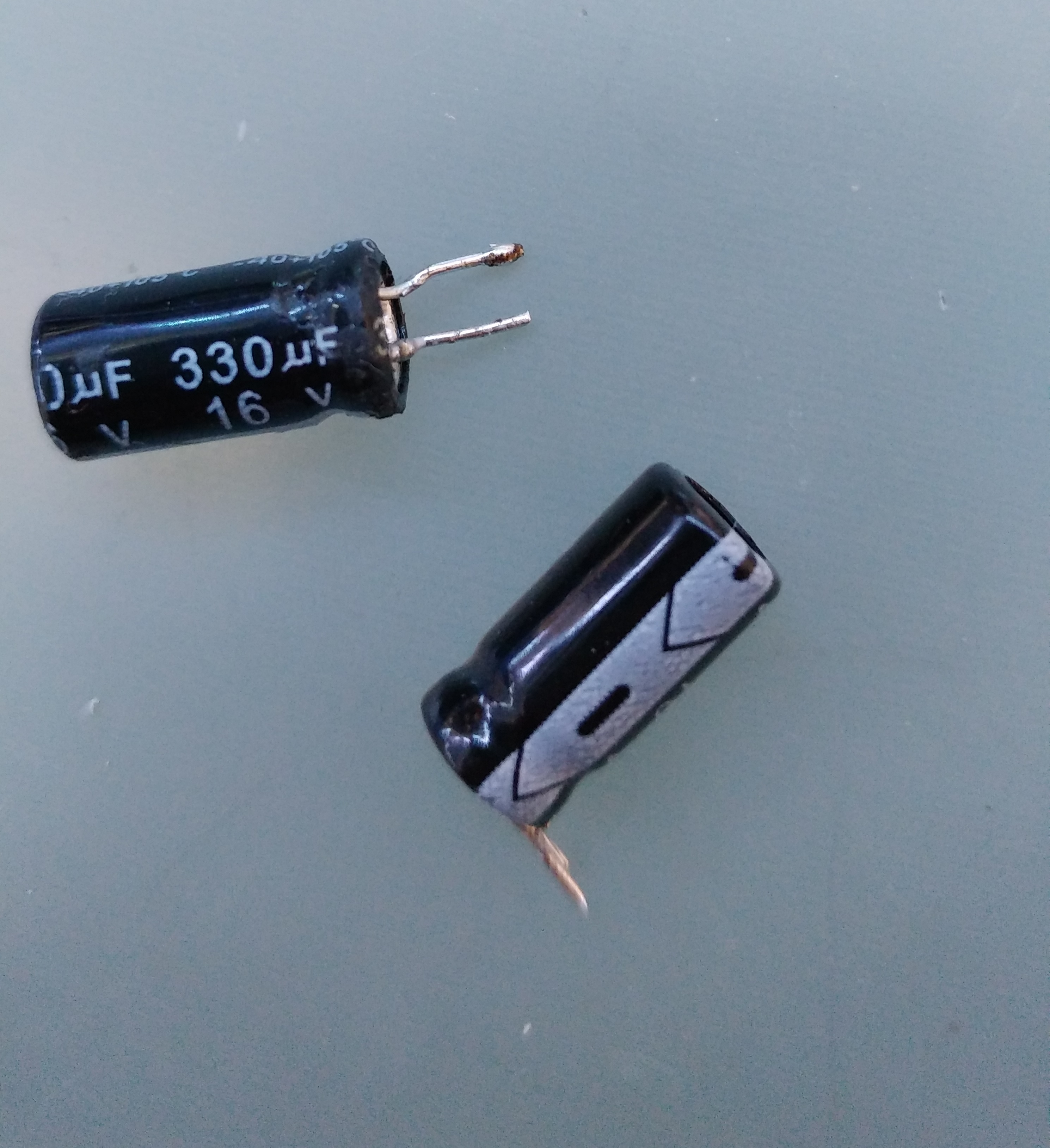
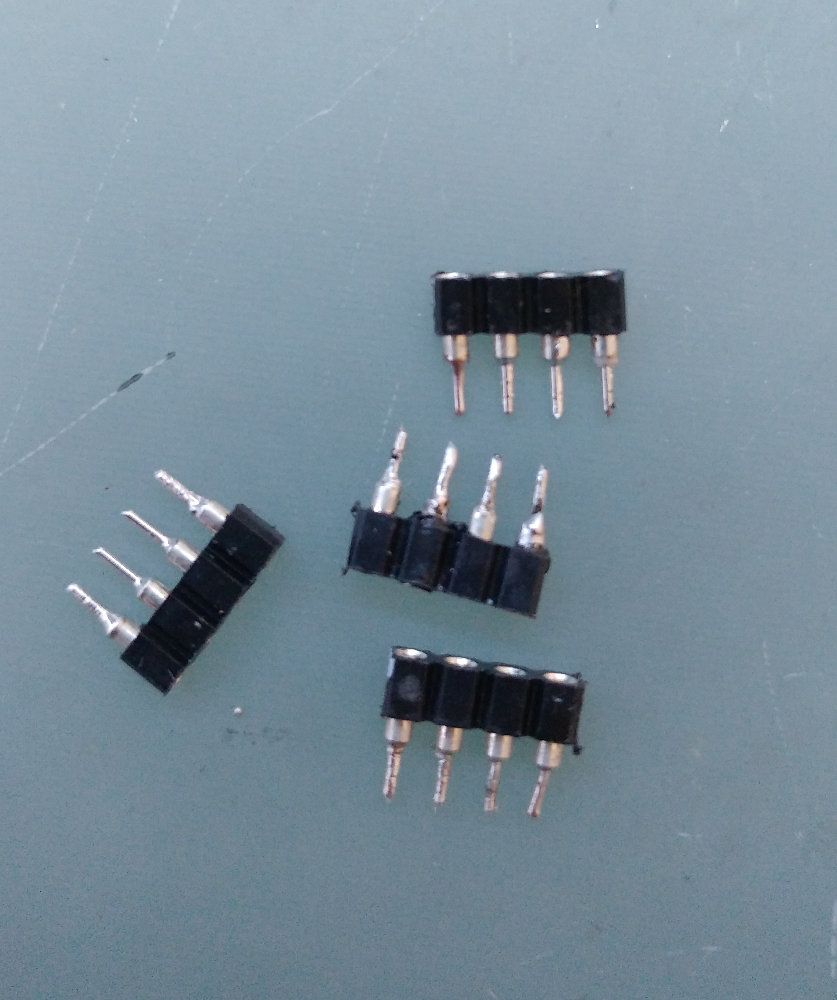
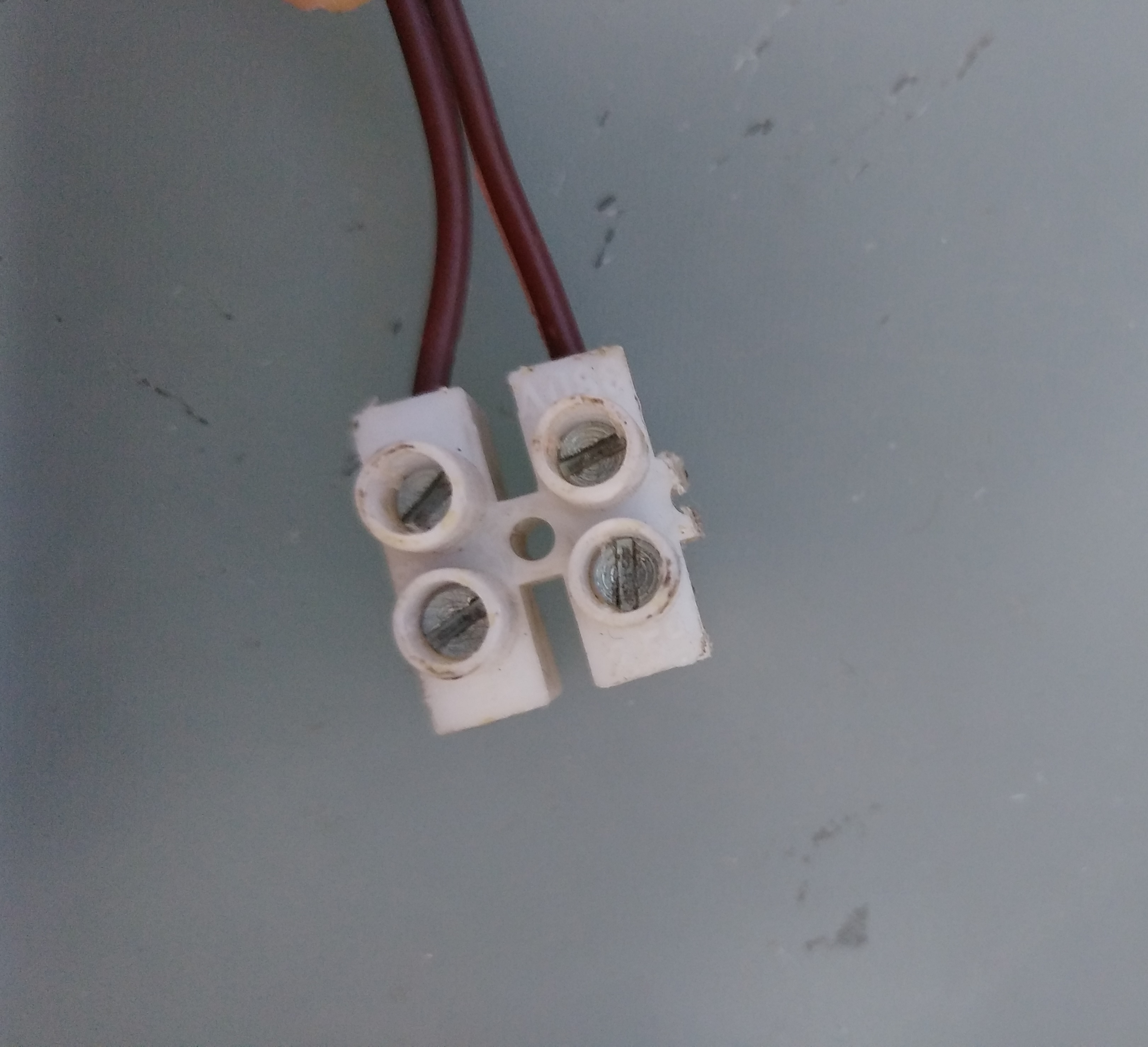

There is a full list of what you need for this project, i savaged most of the components from stuff i had laying around, but you can easily buy them.
- AtTiny45/85: The brain of this project, you can use even an arduino board for this but i think it's way too overpowered.
- 5V Voltage regulator: i used a CJ78M05 to provide 5 volts for the Attiny.
- LM386: op-amp that runs the speaker.
- Speaker/Piezo: chose a loud one , not to high in impedance.
- Relay: Electromagnetic switch used to turn off the Amp in order to save power when the alarm is in stand-by, i used a TX2-3V even if i'm going to drive it with 5v, that should be fine.
- Optocoupler: A little IC to isolate the coil of the relay from the Attiny, i used an EL817 but you can use whatever you want.
- NPN transistor: to drive the relay.
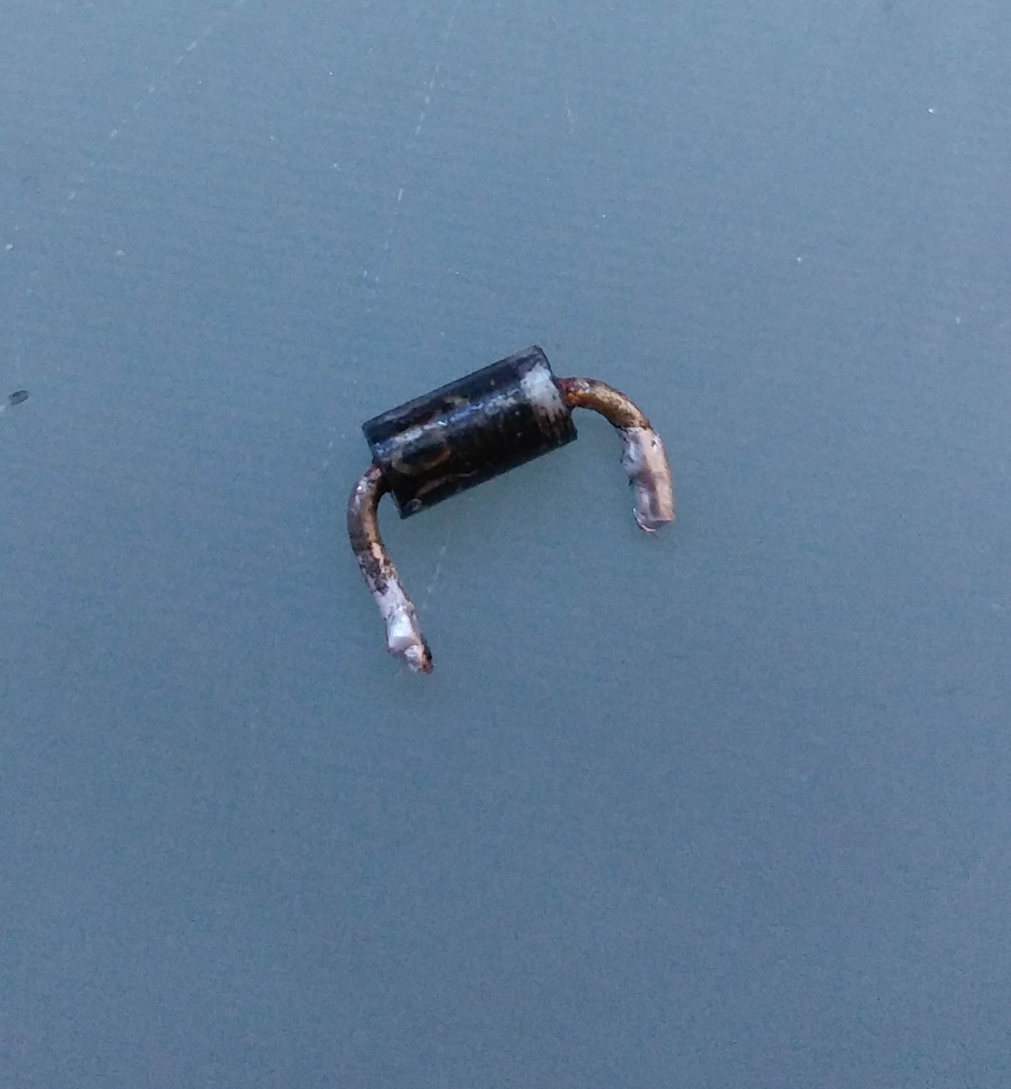
- Diode: to protect the circuit from the high voltage spikes of the coil discharging when the relay goes off.
- Reed Switch: a magnetic switch to detect the door position using a magnet.
- Magnet: i savaged this from an old hard disk.
- Capacitors: you'll need a 10 uF one to set the gain of LM386 and two 300uF, one to stabilize the power line and one for the speaker output.
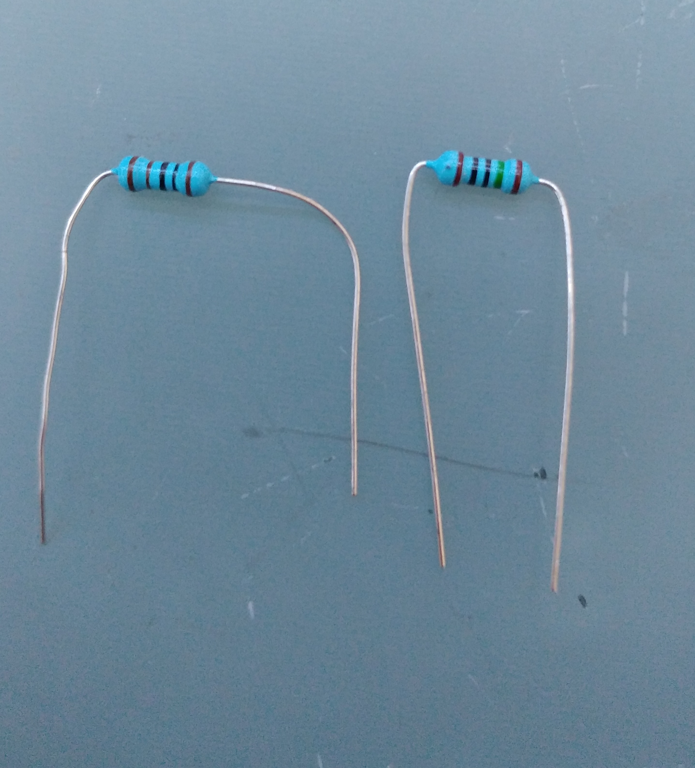
- Resistors: one 1kOhm for the base of the transistor,one 1MOhm as a pulldown resistor for the reed switch input, i used such a high resistance one to save power when in stand-by, and a resistor for the input of the optocoupler.
You need to calculate the value of this last one based on the datasheet of your optocoupler: in my case the datasheet showed an ideal current flow of 20mA trough the infrared led of the optocoupler, so as i'm driving it with 5v i calculated the resistance i needed using Ohm's law :
R=V/I --> R=5v/0,002A --> R=250Ohms
- Switch: connected with a long cable to turn on and off the alarm.
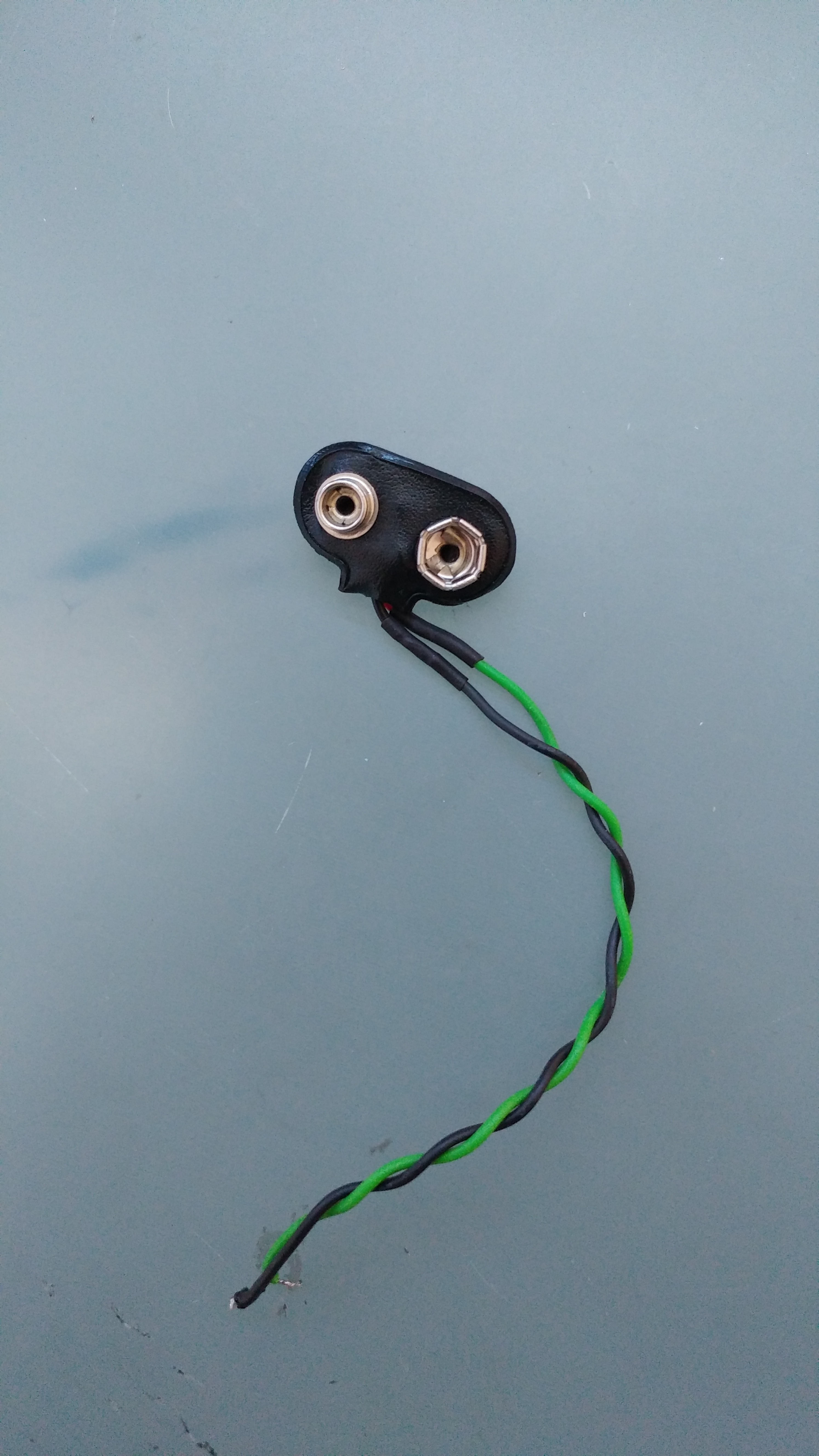
- Battery lead+9v battery.
- Perf board: i'm using one with ground connection over one side to make the circuit cleaner (not the one in the picture).
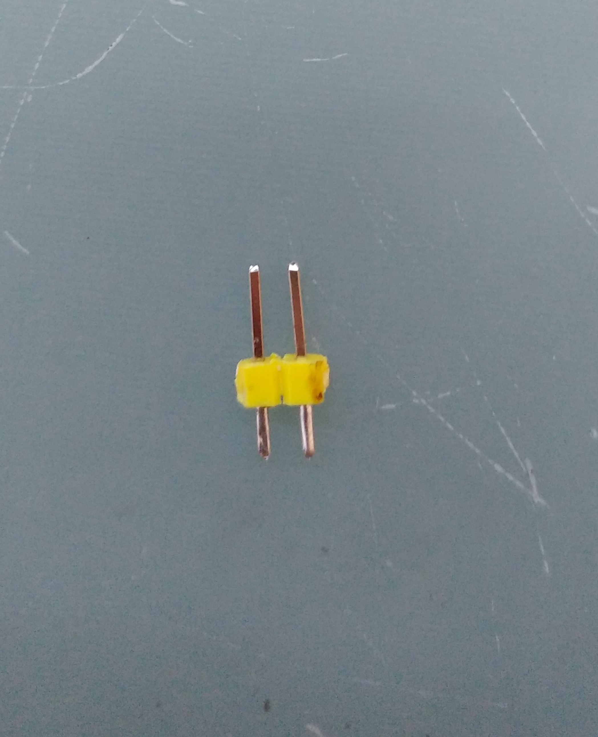
- header pins for IC's and speaker, screw terminal for the switch: raccomended but not strictly necessary.
- Plastic case: again, raccomended but you can mount in on the door even using double sided tape or you can even 3d Print one.
Program ATTiny45
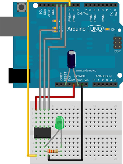
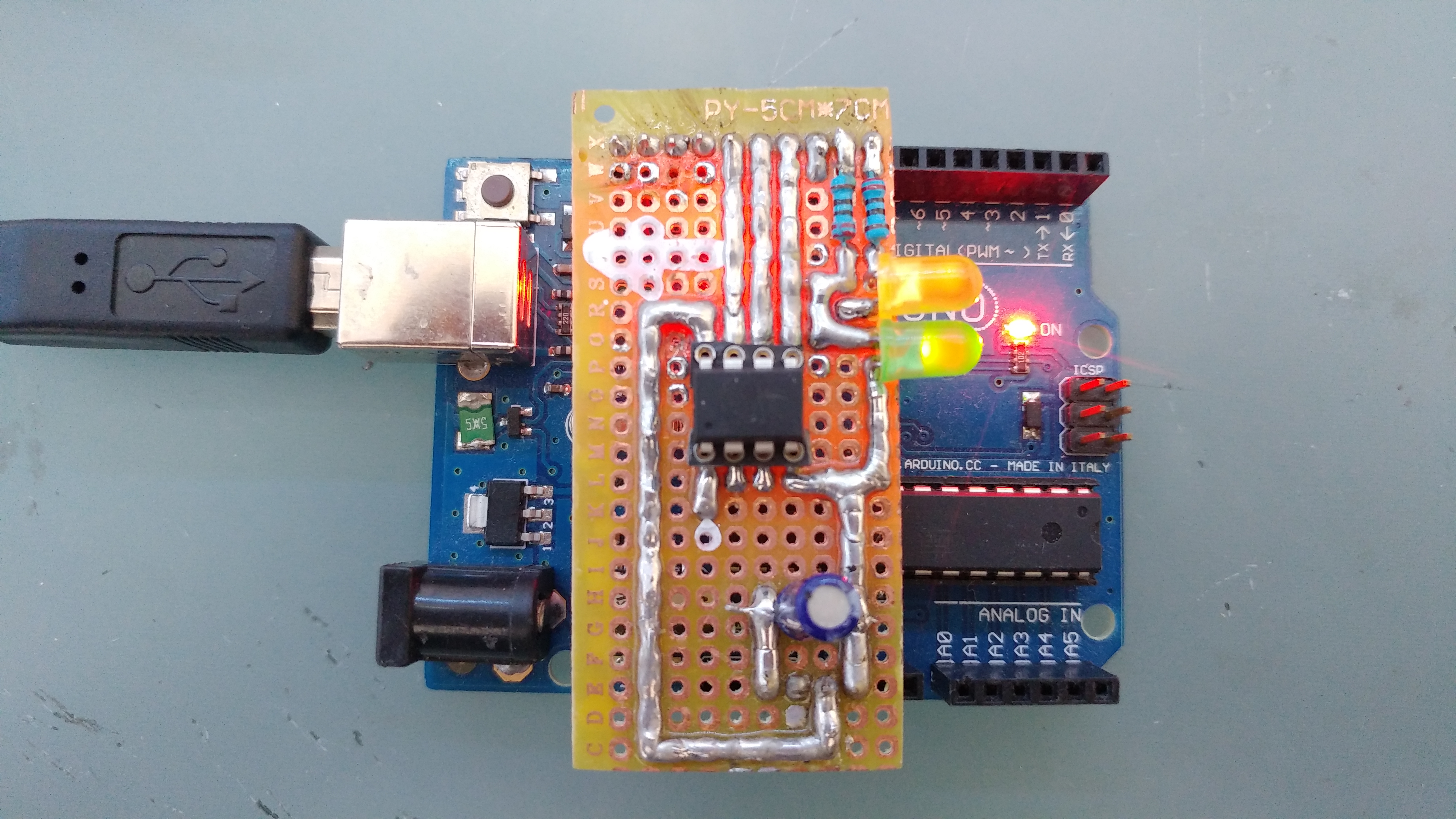
As you may have noticed you can't plug the ATTiny into your usb port to program it, you will need an ISP programmer. If you don't have such a programmer you can easily use an arduino board as an ISP programmer as i did. Here are the steps you need to follow:
- Upload the "Arduino ISP" sketch that you can find in the examples of the Arduino IDE to an Arduino board.
- Connect the ATTiny to Arduino in the way the picture shows, you can even make a shield as i did to make it easy to reprogram in the future.
- Connect Arduino to an usb port and open the IDE,
- In there open "Tools" tab and "Programmer" and select "Arduino as ISP".
- Open "File" ,"Preferences" and in the Additional Boards Manager URLs give this url: https://raw.githubusercontent.com/damellis/attiny/...
- Open "Boards" , "Board Manager"and in there scroll down the list where it says "attiny by Davis A. Mellis". Click on that and install it. At this point you should be able to see ATTiny in the board list.
- Now in the board menu select ATTiny and in "Processor" chose the one you have, on "Clock" select "Internal 8Mhz" and then click "Burn bootloader".
Downloads
Breadboard Circuit
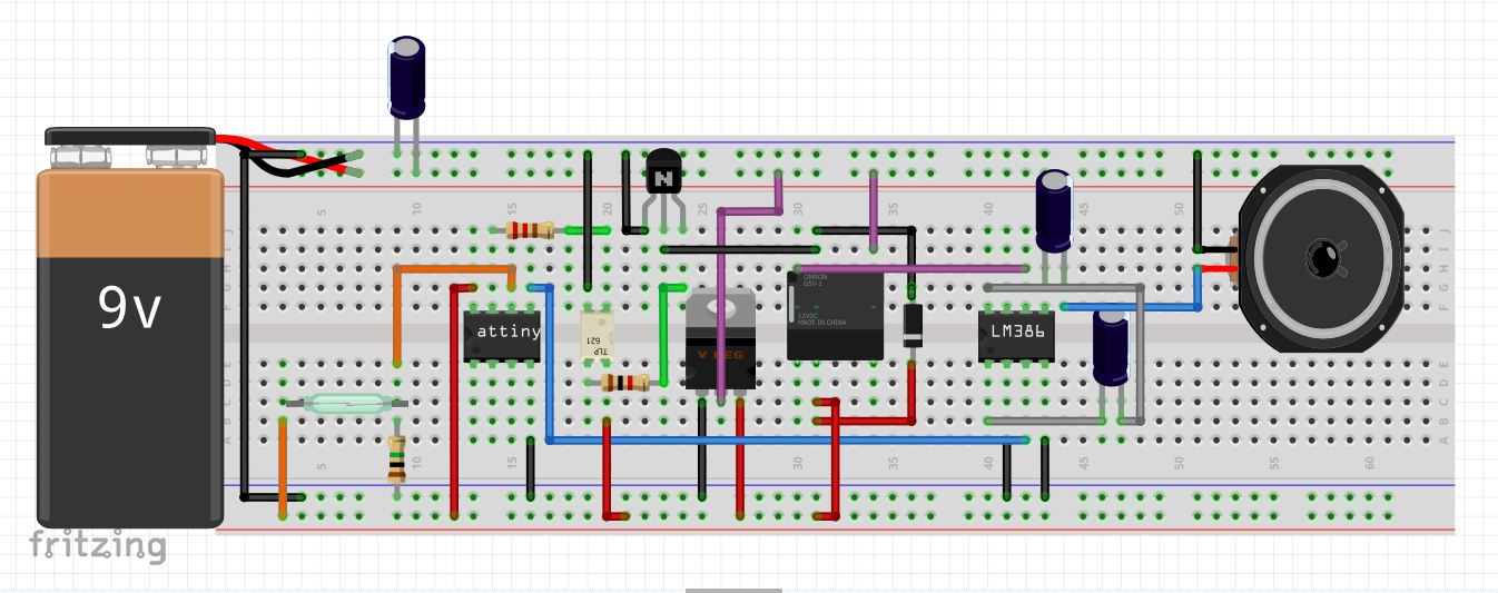
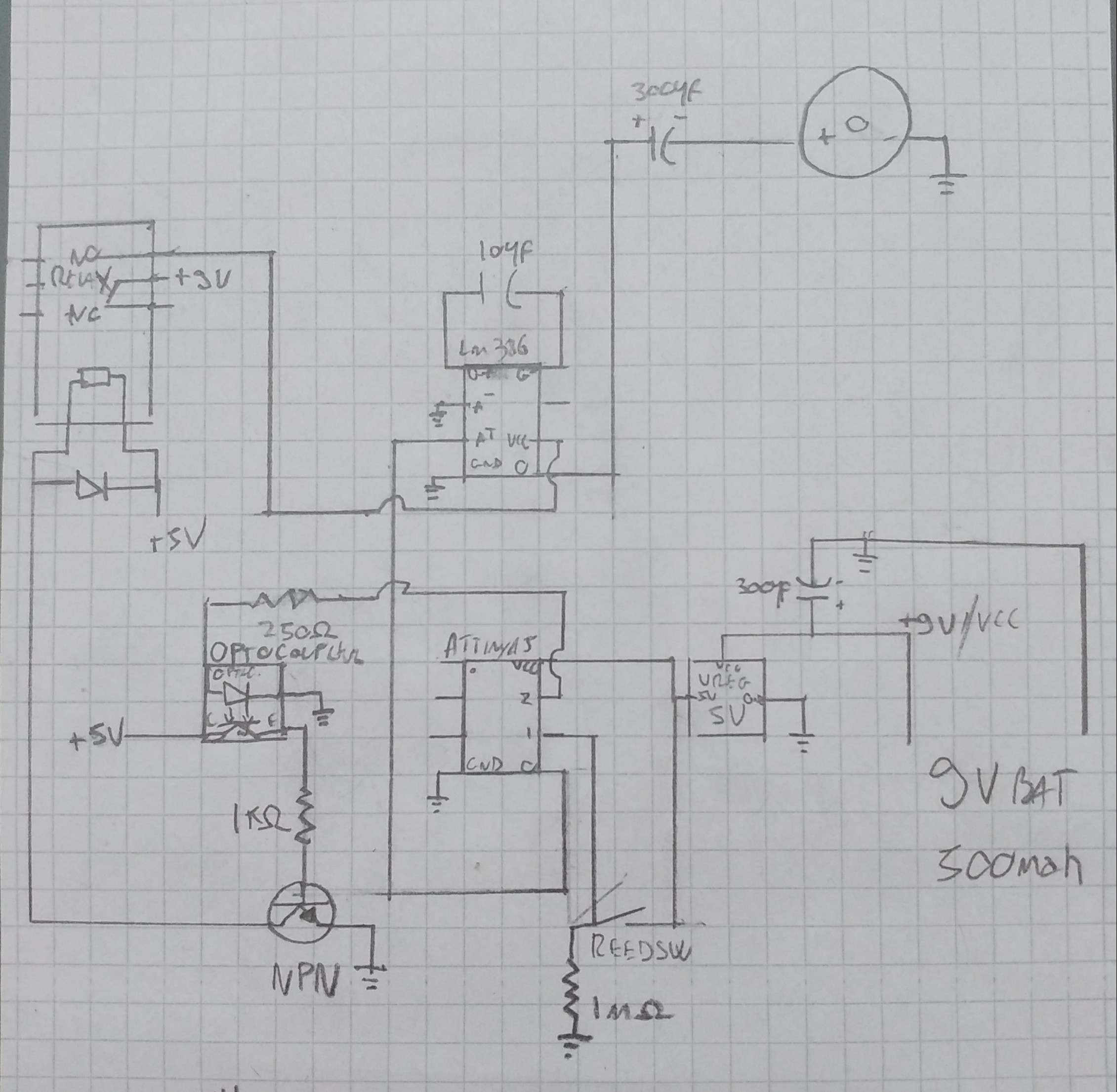
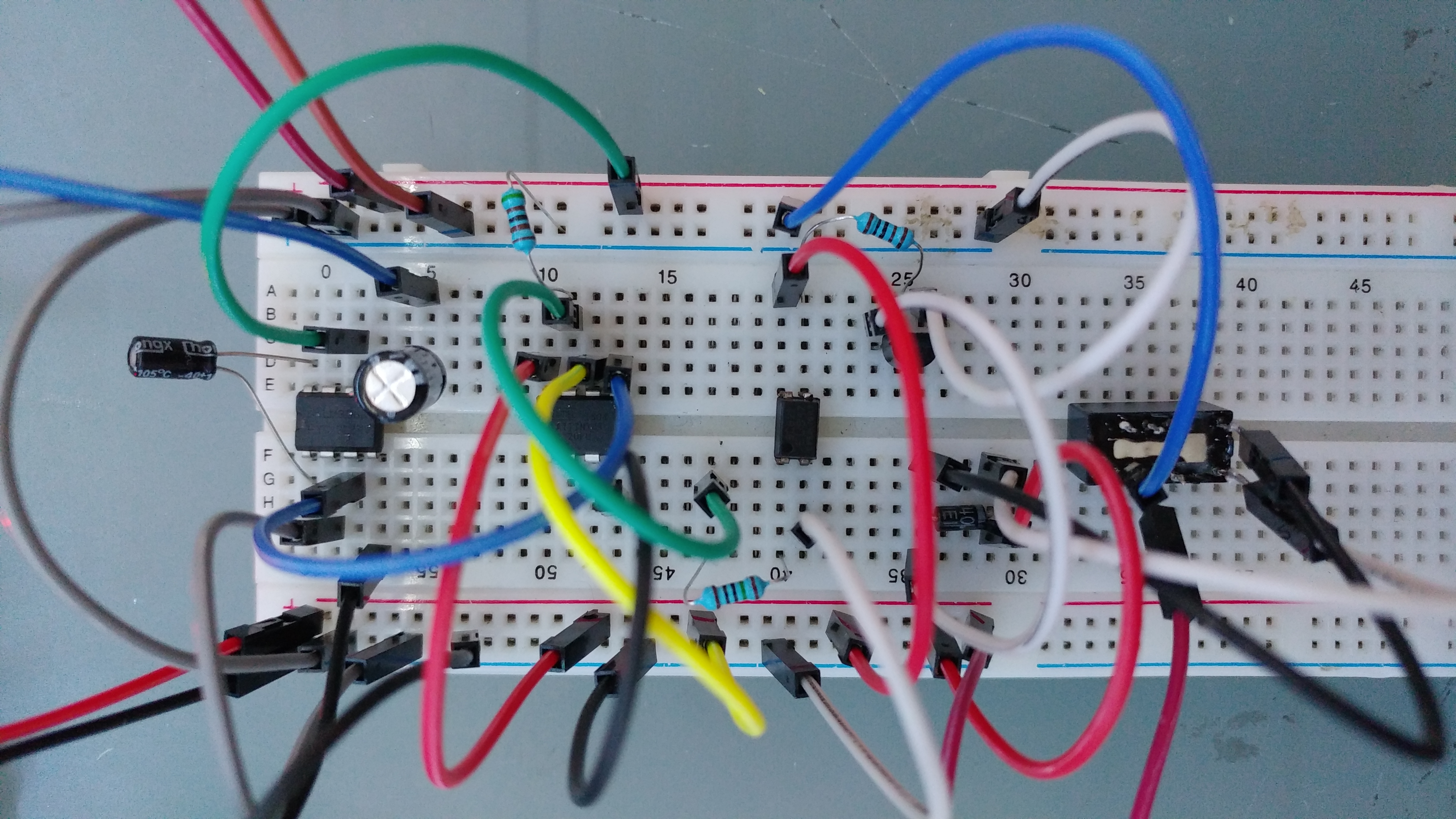
Now you need to make a Breadboard prototype according to the schematics above to test everything works.
Perf Board Circuit
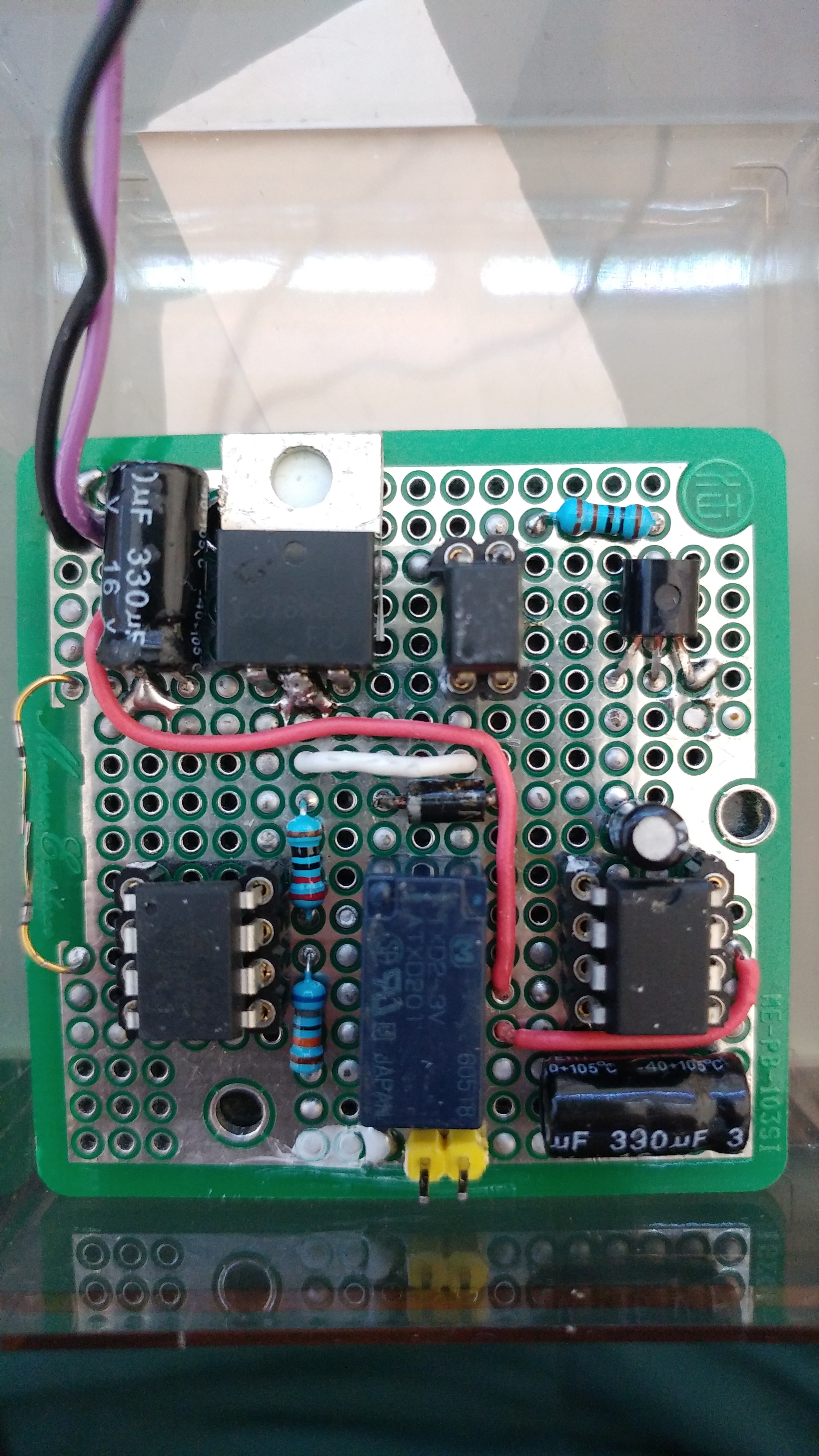
Now once you have tested everything works you can move the Breadboard circuit to a perfboard one. Using a PCB with a Grounded side saves you a lot of time and space, and using sockets for all the IC's is also a good idea. once you finished test the circuit is still working correctly and then add a switch in series with the positive lead of the 9v battery connector using the Screw connector and long wires.
Case and Mounting
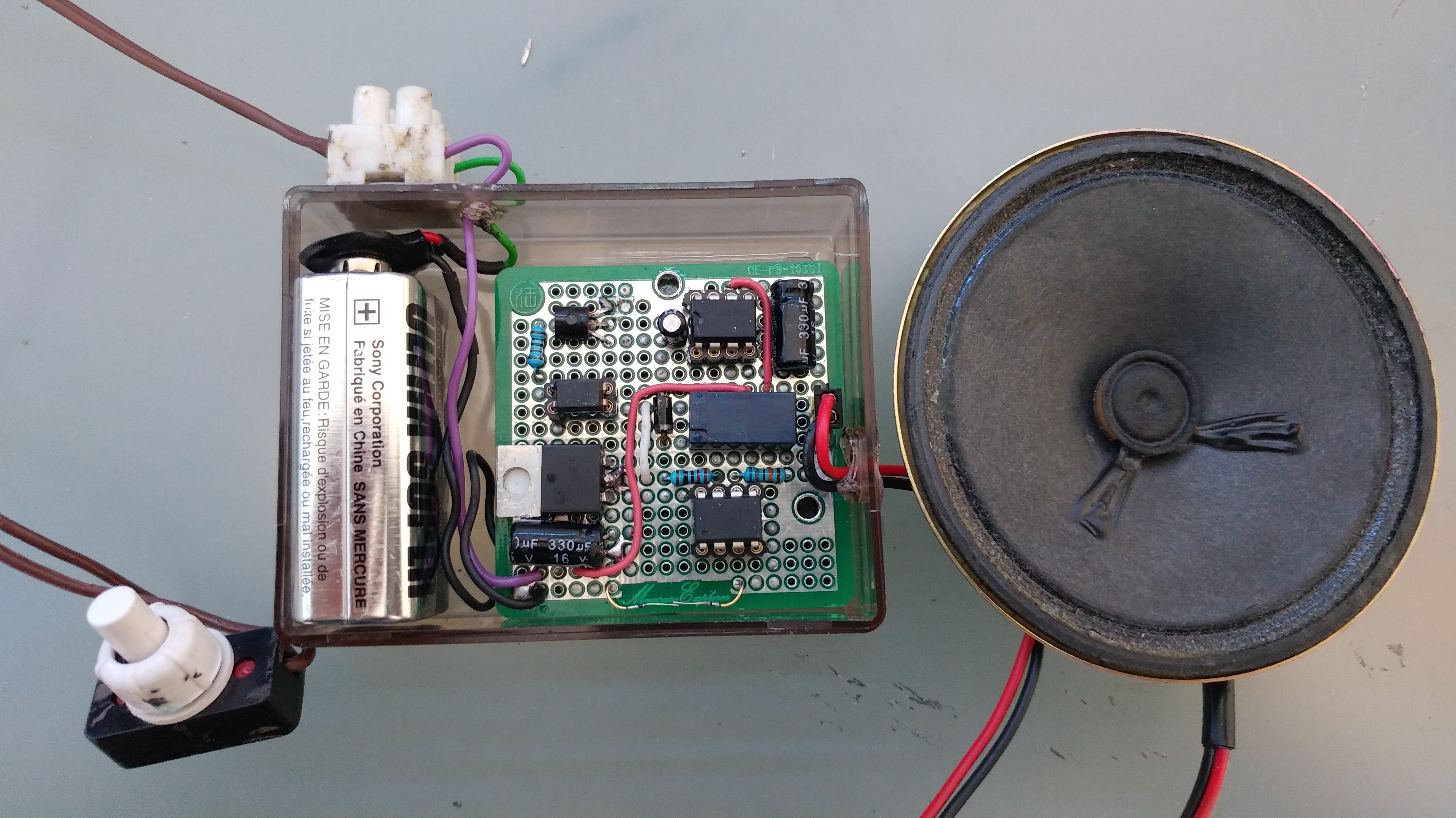
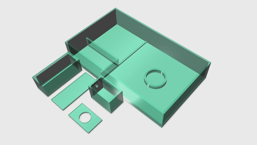
If you like you can put the whole thing inside a case or a box to keep everything nice and compact, you can even 3D print one similar to the one in the picture i designed. Mount the box above the door using doublesided tape or screws and the magnet on the door itself in correspondence to the reed switch,be sure to use a strong magnet. Hide the power switch somewhere or make it difficult to acess and you are done.
You Finished
Here you have it, at this point you should have a functioning door alarm with a long lasting battery life, mine draws around 1mA in stand-by and using such a 9v battery that tipically has 500mAh it should last for around 500 hours. If you want to save even more power you can avoid the voltage regulator and power the circuit directly with 5 volts reducing the power consuption to just some uA , however in this way the alarm will have a lower volume.
If you have any suggestions or issues while building it please use the comment section, i will provide soluctions for you no problem.