Don't Forget Your Raspberry RF ID Card!
by rgrokett in Circuits > Raspberry Pi
6397 Views, 28 Favorites, 0 Comments
Don't Forget Your Raspberry RF ID Card!
Overview
Using a Raspberry Pi (even a Zero!) and an RFID Card reader, along with relay, LED, buzzer and some python code gives you the ability to install electronic locks in your house or office.
A company called ControlEverything offers a number of interesting products for Arduino, Particle, Raspberry and their own $5 Onion Omega 2 (a Linux computer with WiFi built-in. Kind of a mix between an ESP8266 and a Raspberry Zero!).
They offer a range of sensors and modules that use the I2C interface or UART interfaces on the Raspi.
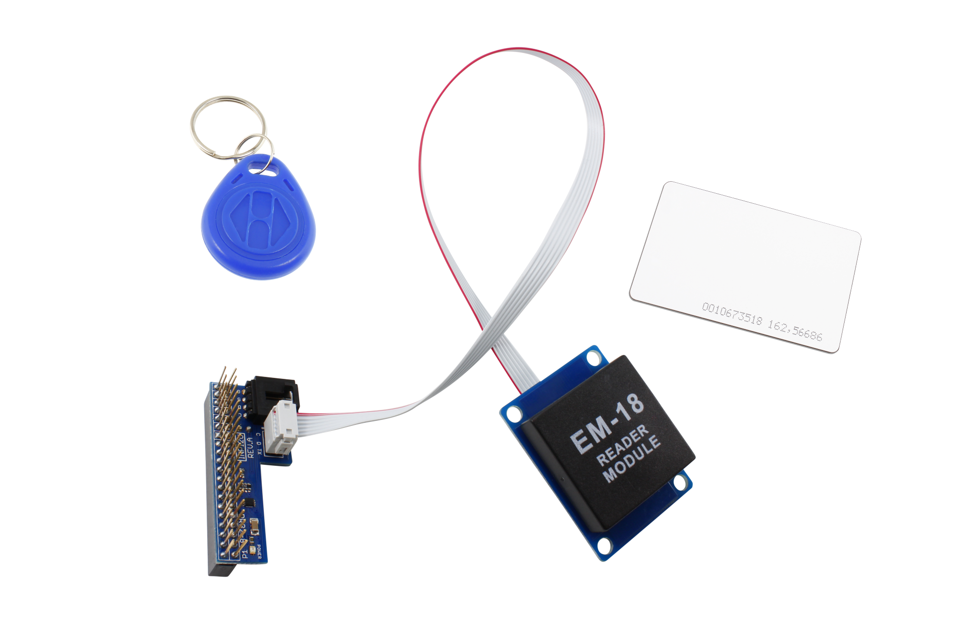
One item they have is the EM18 RFID reader module.
The EM18 RFID Receiver for Raspberry Pi uses the UART interface for communication.
RFID
RFID (Radio Frequency Identification) uses electromagnetic fields to read, monitor and transfer data from tags attached to different objects. It is not necessary that the cards are to be in visibility of the reader, it can be embedded in the tracked object. The tags can be actively powered from a power source or can be passively powered form the incoming electromagnetic fields.
EM-18 RFID reader module is one of the commonly used reader and can read any 125KHz tags. It features low cost, low power consumption, small form factor and easy to use.
Project
This project lets you use a Raspberry Pi to act like an electronic door key & lock. You wave your RFID badge and the Raspi lights an LED, sounds a buzzer and engages a 120v/220v relay that could be connected to an electric lock or solenoid to unlock the door. After 5 seconds, the lock reengages and the LED and buzzer turn off. From inside the door, you can have a push button that unlocks the door for 5 seconds so you can leave without an RFID.
Parts
- Raspberry Pi Zero, B+, 2, or 3 running Raspian Jessie
- RFID module from ControlEverything which includes a Pi adapter and RFID key
https://www.controleverything.com/content/RFID-Rea...
You can substitute the Grove RFID instead. Be sure to set it to UART mode:
https://www.seeedstudio.com/Grove-125KHz-RFID-Read...
http://wiki.seeedstudio.com/wiki/Grove_-_125KHz_RF...
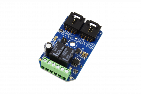
- 5v to 120v/220v ControlEverything I2C relay
https://www.controleverything.com/content/Relay-Co...
Or substitute a Grove Relay module
https://www.seeedstudio.com/Grove-Relay-p-769.html
http://wiki.seeedstudio.com/wiki/Grove_-_Relay
- 5V Grove Buzzer Module
https://www.seeedstudio.com/Grove-Buzzer-p-768.htm...
http://wiki.seeedstudio.com/wiki/Grove_-_Buzzer
- LED with 220 ohm resistor or Grove LED module
https://www.seeedstudio.com/Grove-LED-p-767.html
- Momentary contact push button
- RFID tags (if more than the one included)
https://www.seeedstudio.com/RFID-tag-combo-(125khz... - Circuit board or breadboard or Grove base shield, cables and connectors
https://www.seeedstudio.com/Grove-Universal-4-pin-...
- Wire, box, etc.
Wiring
Using the ControlEverything EM18 RFID (or Grove) hardware, it is a straight forward task to connect everything together.
Note that on the Raspberry Zero, you will need to add a connector (i.e. solder!) so be aware. The other Pi’s come with pin connectors already installed.
Note for Grove wiring, you will need to use Grove universal connectors and solder to a board as they no longer carry a Raspberry Pi shield.
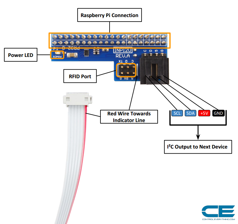
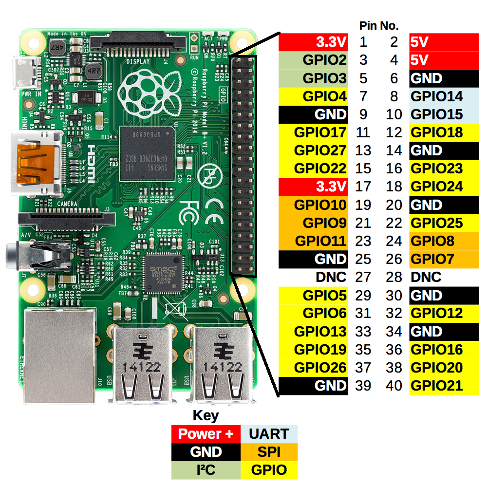
Take the ControlEverything Raspberry Pi I2C Adapter and line up with the P1 pin on the adapter facing the Pin 1 on the Raspberry Pi GPIO as shown in Fig.1
The RFID module uses the Raspberry’s UART connections (GPIO 14, 15, +5v, Gnd). If you use the Grove RFID, set it to use the UART. This is a Serial 9600 baud connection between the Raspi and the RFID module.
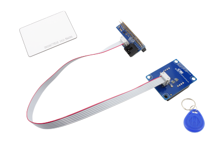
Next plug the included grey cable into the Raspberry Pi Adapter. (Fig.2)Fig
Adapter 6 pin port, making sure the red wire is facing the white indicator line on the adapter board.
Then plug the grey cable into the RFID module, again with the red wire facing the white indicator line.
Simple Start
NOTE: This assumes you already have a working Raspi using Raspian Jessie OS and can access via SSH or terminal. There are plenty of how-to's for setting up and using your Raspberry, so I'm not repeating them here. :)
Once you have plugged in your RFID module to the Pi, you can try it out.
Log into your Raspi using SSH or a terminal program.
You can also go to GITHUB https://github.com/rgrokett/RFIDReaderPi and use the files from there
You may need to install some python modules first:
$ sudo apt-get install python-pip
$ sudo pip install pyserial
Create a file called “rfidtest.py”
$ nano rfidtest.py
Edit the file using below.
import serial
# For PiB+ 2, Zero use:
ser = serial.Serial('/dev/ttyAMA0', 9600, timeout=1)
# For Pi3 use
#ser = serial.Serial('/dev/ttyS0', 9600, timeout=1)
while True:
    string = ser.read(12)
    if len(string) == 0:
        print "Please wave a tag"
    else:
        string = string[1:11]   # Strip header/trailer
        print "string",string
        if string == '650033A2E5':
            print "hello user 1
Note for Raspberry Pi 3 owners:
Note that for Pi3 only, you need to comment out the Pi2 line and uncomment the Pi3 line as Pi3 uses /dev/ttyAMA0 for Bluetooth.
#ser = serial.Serial('/dev/ttyS0', 9600, timeout=1)Also note that on the Pi3, you need to add the following line to /boot/config.txt:
$ sudo nano /boot/config.txt
Append:
#Enable UART
enable_uart=1
Then reboot your Pi3.
All Raspberries:
To run the python program, just type:
$ sudo python ./rfidtest.py
Tap your RFID card or fob against the EM18 module. The program should print out the ID string. You can edit the rfid.py to update the string with your ID’s string.
Part 2 Wiring
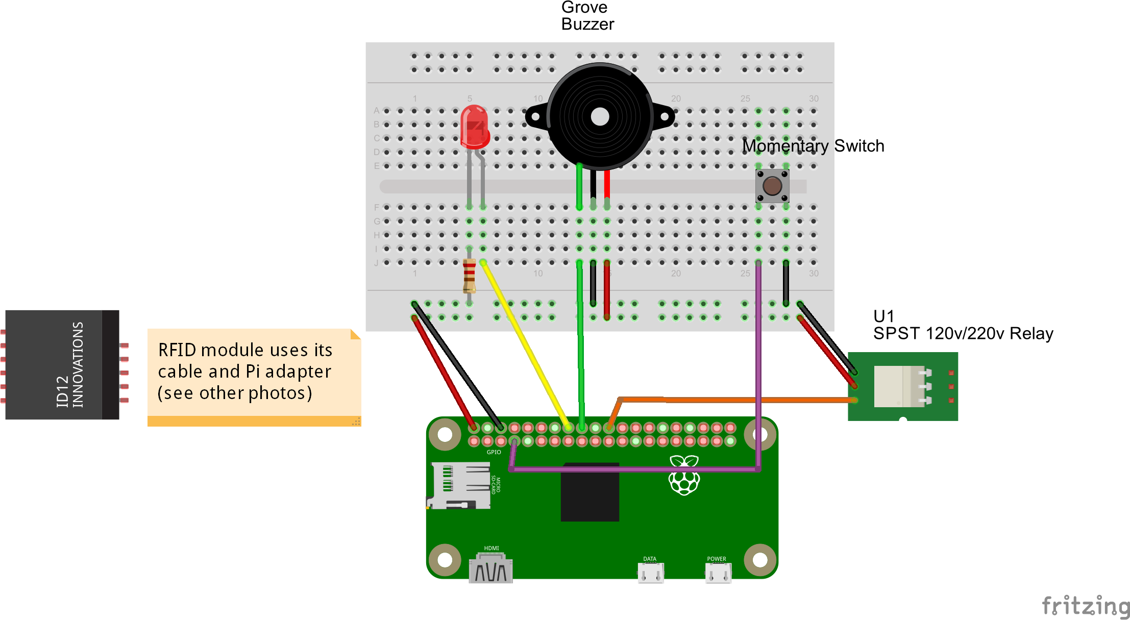
Use the diagrams and photos to assist in wiring the LED, Buzzer, Relay and button. Note that the Grove wiring will be slightly different as it uses +5v, GND and Signal leads, instead of just two wires.
If you are using the ConnectEverything I2C Relay module, you just plug it into the Pi Adapter I2C port.
For the other devices (LED, Buzzer, Switch and relay) connect using the diagram and pins shown in the figures above.
Note for Grove wiring, you will need to use Grove universal connectors and solder to a board as they no longer carry a Raspberry Pi shield.
The GPIO pins for Raspberry Zero, B+, 2 and 3 are identical, so the same diagram will work for either.
When you initially turn on your Raspberry, the LED, buzzer and relay should stay off, but it is possible that they come on. Assuming no wiring errors, these will turn off when you first run the Reader program described next.
More Advanced Reader Software

There are two possible Relays supported here. The Grove version uses three wires (+5v, GND, GPIO Signal) while the ControlEverything uses I2C interface.
For I2C, you must activate the I2C interface on your Pi. This is not needed for Grove.
1. $ sudo raspi-config
2. Select “Advanced Options”
3. Select “I2C”
4. Answer “Yes” to Would you like the ARM I2C interface to be enabled?
5. Answer OK and select “Finish” to exit.
6. $ sudo reboot
After reboot, log back in and enter:
$ sudo i2cdetect -y 1
If you have no I2C devices plugged in, you will see the above Fig.1
Once you plug in a device and rerun the command, you should see it show up in the list. (Probably need to reboot, if you didn’t power down before plugging it in.)
Note that the EM18 RFID module isn’t an I2C device, so doesn’t show up.
The ControlEverything 1 or 2 channel relay module is I2C, so should show up in the I2C devices list as 0X41.
Get the software from GitHub:
GITHUB https://github.com/rgrokett/RFIDReaderPi
$ git clone <a href="https://github.com/rgrokett/RFIDReaderPi.git" rel="nofollow">https://github.com/rgrokett/RFIDReaderPi.git</a>
If you are using the I2C relay, you need to change the line
I2C = OFF # Grove Relay
to
I2C = ON # I2C Relay
If necessary, you can change which GPIO pins you are connecting your LED, Buzzer, Grove Relay and Push button as needed. But you cannot use the I2C or UART GPIO pins.
Add your RFID card numbers to the CARDS list in the program. If you don’t have the number from the rfid.py program, any card you wave while running this program will be printed on the screen, but will not “open” the door.
Run the program using:
$ sudo python reader.py
The program will display a message every few seconds watching for a card to read. When it sees one, it will turn on the LED, Buzzer and Relay for 5 seconds, then turn them all off.
If you press the momentary button instead of waving a card, it too will “open” the door.
If you exit the program (Ctrl-C), the relay will engage to “unlock” the door on failure. (The Jurassic Park mode!) This would keep you from being locked out if the Raspi failed.
Note that I did not include error trapping or set up the program to restart on reboot. Also note that the relay will NOT be engaged if the power goes out. This means the door would be “locked”!
A Real System
For a real Door lock system, you need to add the electric lock or solenoid to the Relay. You also need to harden the program and the Pi for failures. (i.e. error trapping and restart at reboot, a battery backup, a case for the RFID module, etc.) If you have many RFID cards, an external file or database would be useful, along with the user’s name.)
See also the version “reader2.py” in GITHUB files for example of these extra features.
Reader2.py Configuration
The reader2.py is a more elaborate version of the door lock controller that stores cards in a file and logs date/time of entries and exits.
To use this version, copy the cards.dat to your /home/pi directory and edit with your card numbers.
$ cp cards.dat /home/pi/cards.dat
$ nano /home/pi/cards.dat
Edit with your card ids and names.
Test the program from the command line using:
$ sudo python reader2.py
Once you verify operation, edit reader2.py and turn off DEBUG messages:
$ nano reader2.py

DEBUG = False
Edit /etc/rc.local and add the following line
$ sudo nano /etc/rc.local

/home/pi/RFIDReaderPi/reader2.py &
exit 0
This will run the program any time you reboot the pi.
A log file of each door entry will be appended to:
/home/pi/rfiduser.log
2016-08-31 13:11:51 00000000 Start...
2016-08-31 13:11:57 E0043DBB00 NOT FOUND
2016-08-31 13:12:05 00000000 Someone Exited
2016-08-31 13:19:29 E0043DBB00 Russell Grokett
2016-08-31 13:19:37 00000000 Stop...
Have Fun!