[Docker Pi Series]How to Use IoT Node (A) Module on Raspberry Pi
by yoyojacky in Circuits > Raspberry Pi
1892 Views, 4 Favorites, 0 Comments
[Docker Pi Series]How to Use IoT Node (A) Module on Raspberry Pi
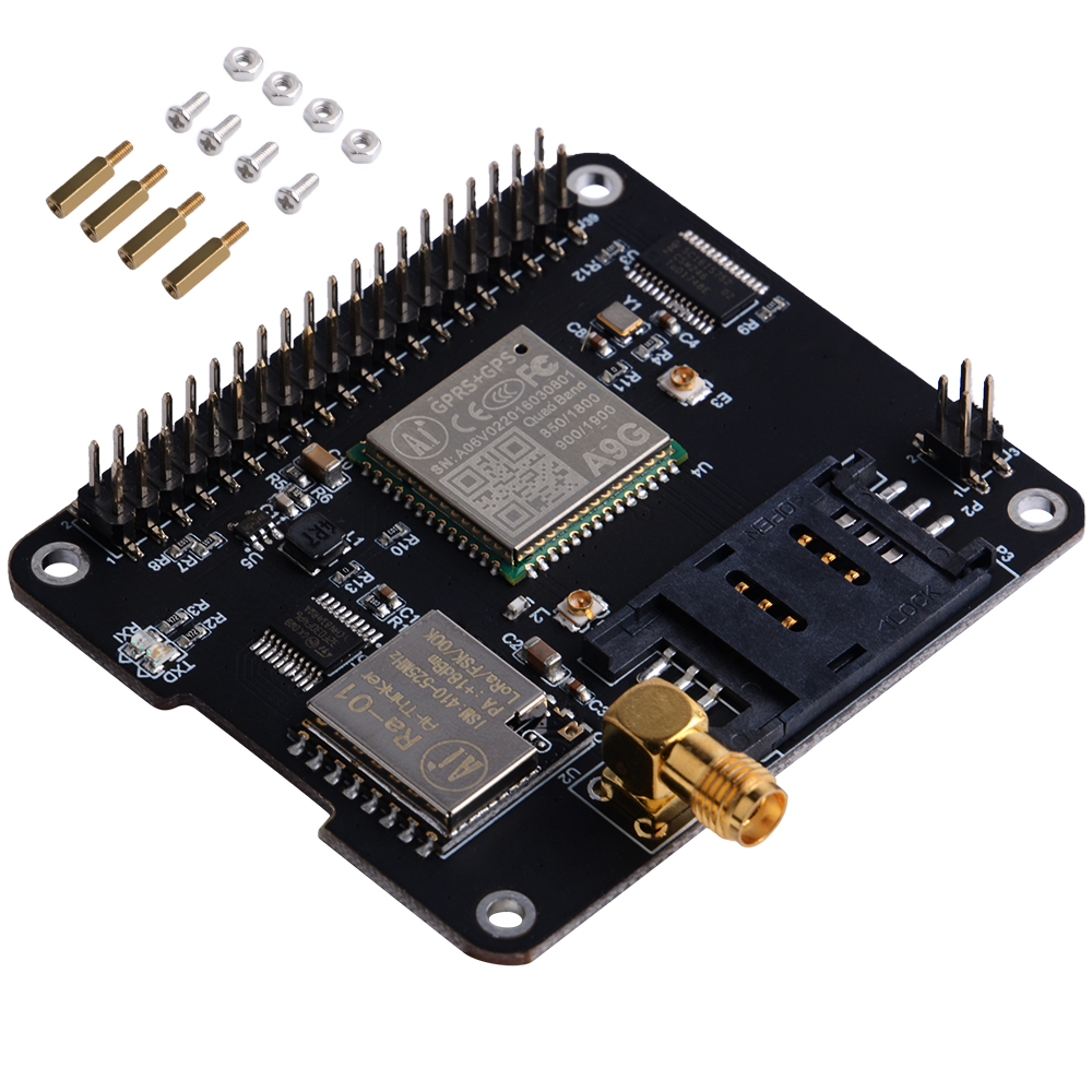
What is IoT Node (A) module ?
IoT Node(A) is one of Docker Pi series module.
IOT Node(A) = GPS/BDS + GSM + Lora.
I2C directly controls Lora, sends and receives data, controls the GSM/GPS/BDS module through SC16IS752, the mainboard only needs I2C support.
Support Raspberry Pi and other similar products.
Supplies
1x Raspberry Pi 2B/3B/3B+/4B/3A+/Zero /Zero W
1x Docker Pi series product : IoT Node(A) module
1x 16GB class 10 TF card
1x 5V/2.5A power supply (5V@3A for Pi 4B)
Features
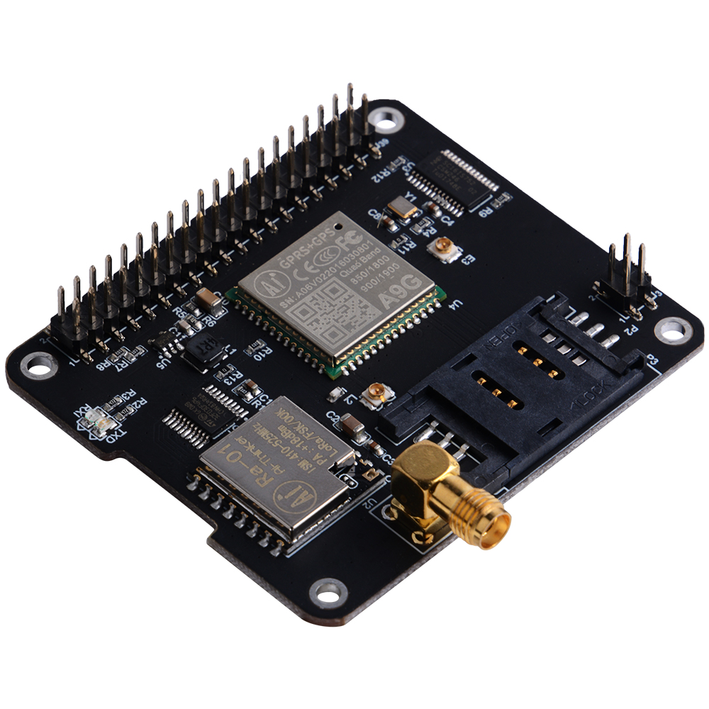
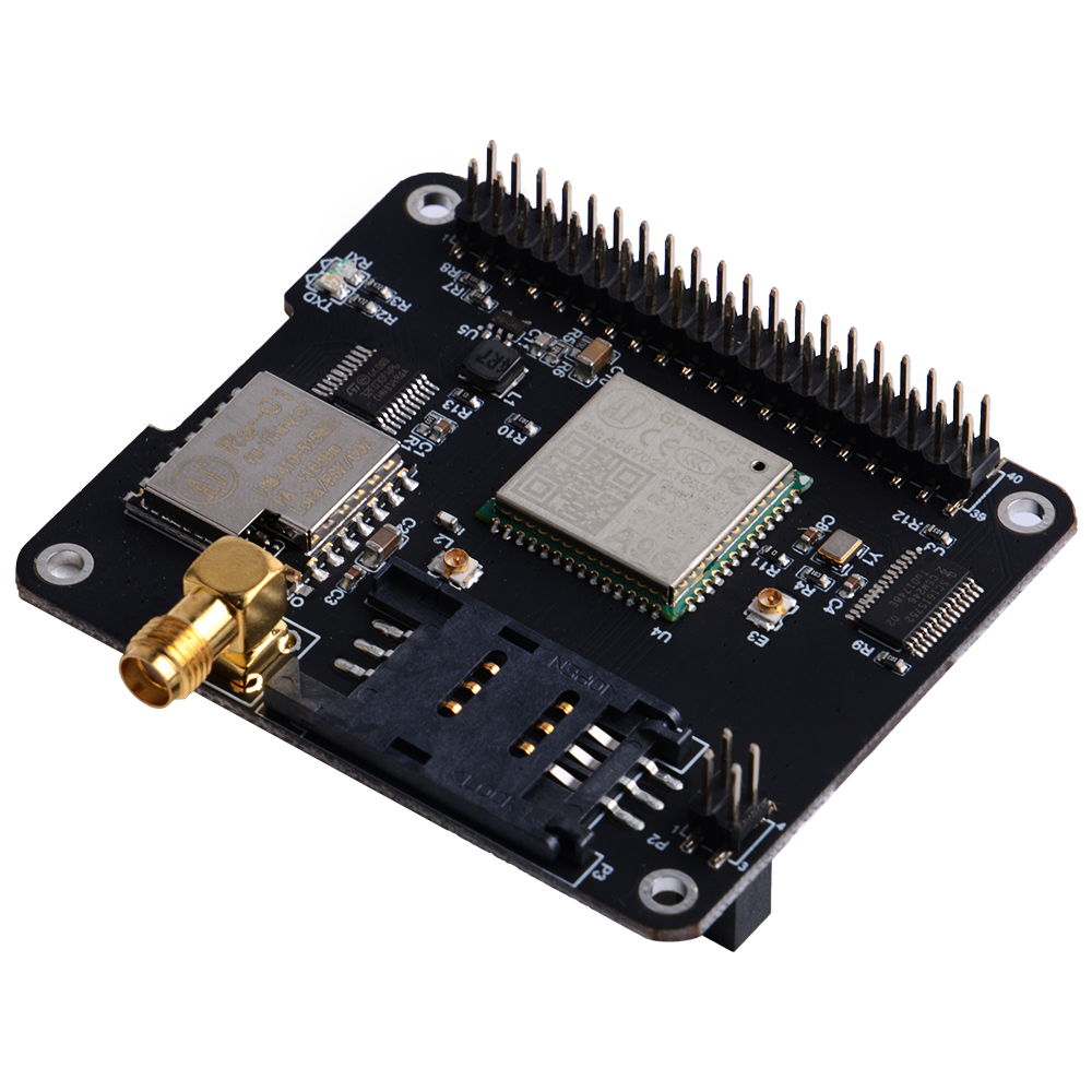
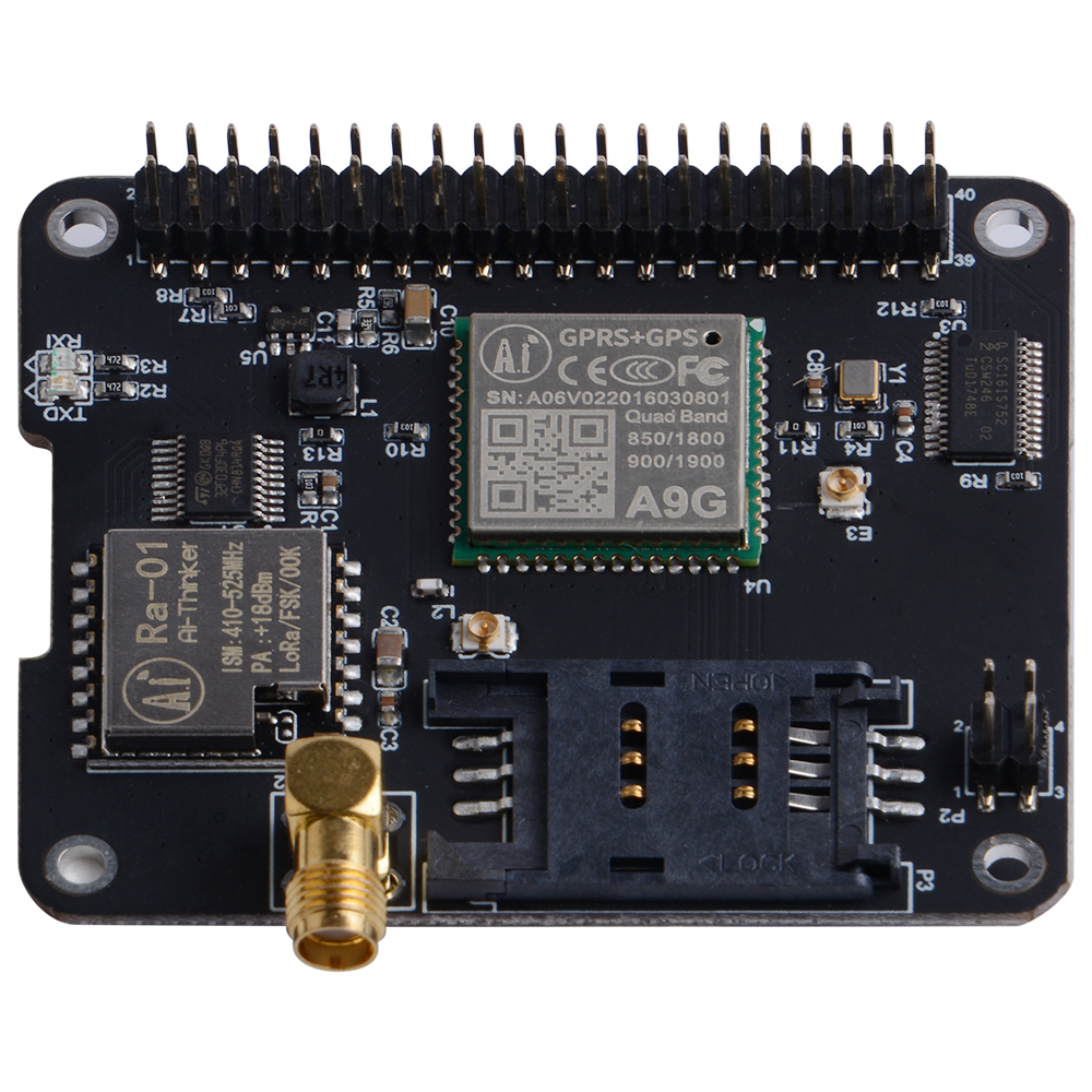
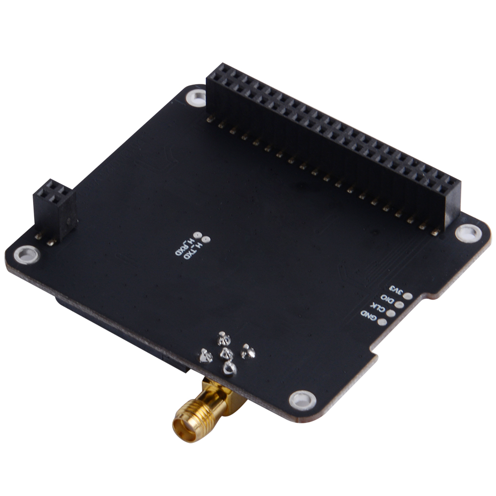
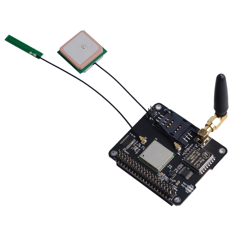
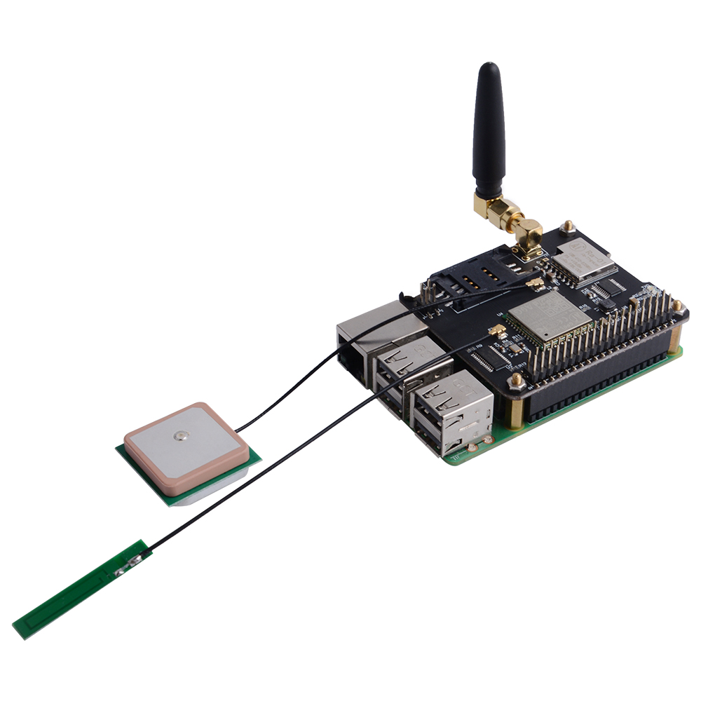
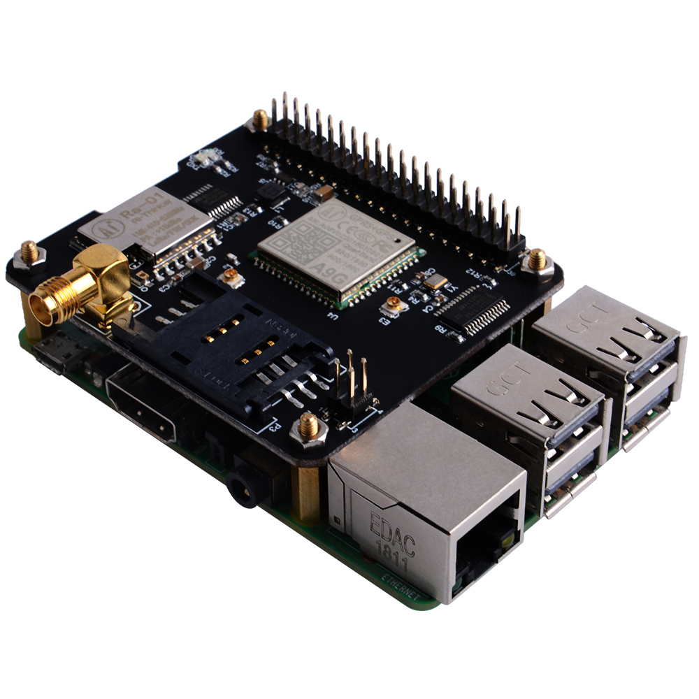
- Docker Pi Series
- Programmable
- Control directly(without programming)
- Extend the GPIO Pins
- GPS/BDS Support
- GSM Support
- Lora Support
- Can Stack with other Stack board
- Independent of the mainboard hardware (require I2C support)
Step1 : Know About the IoT (A) Board
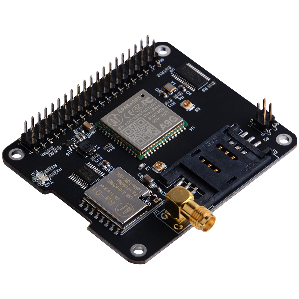
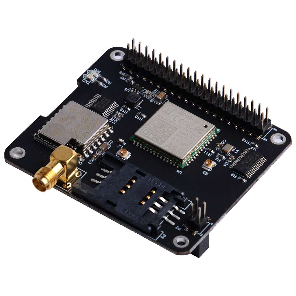
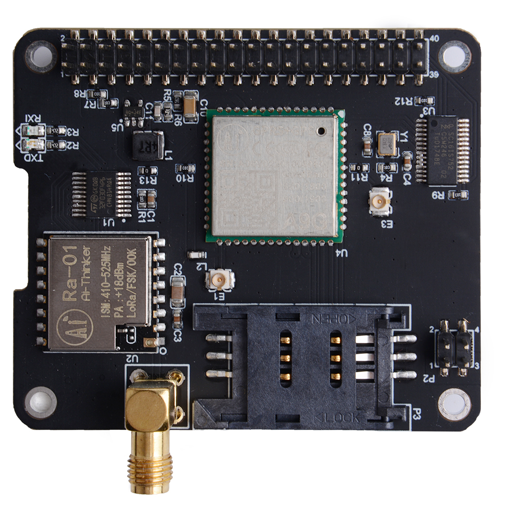
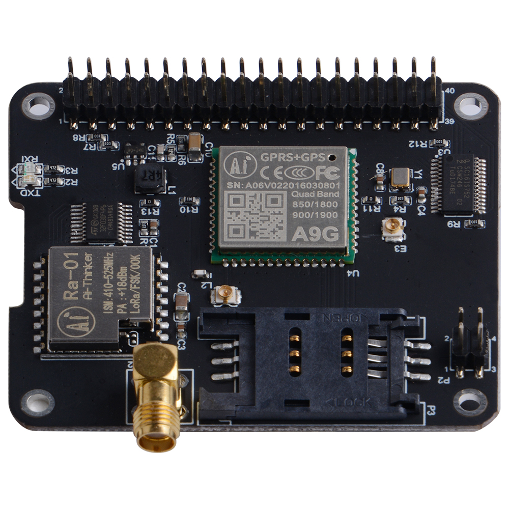
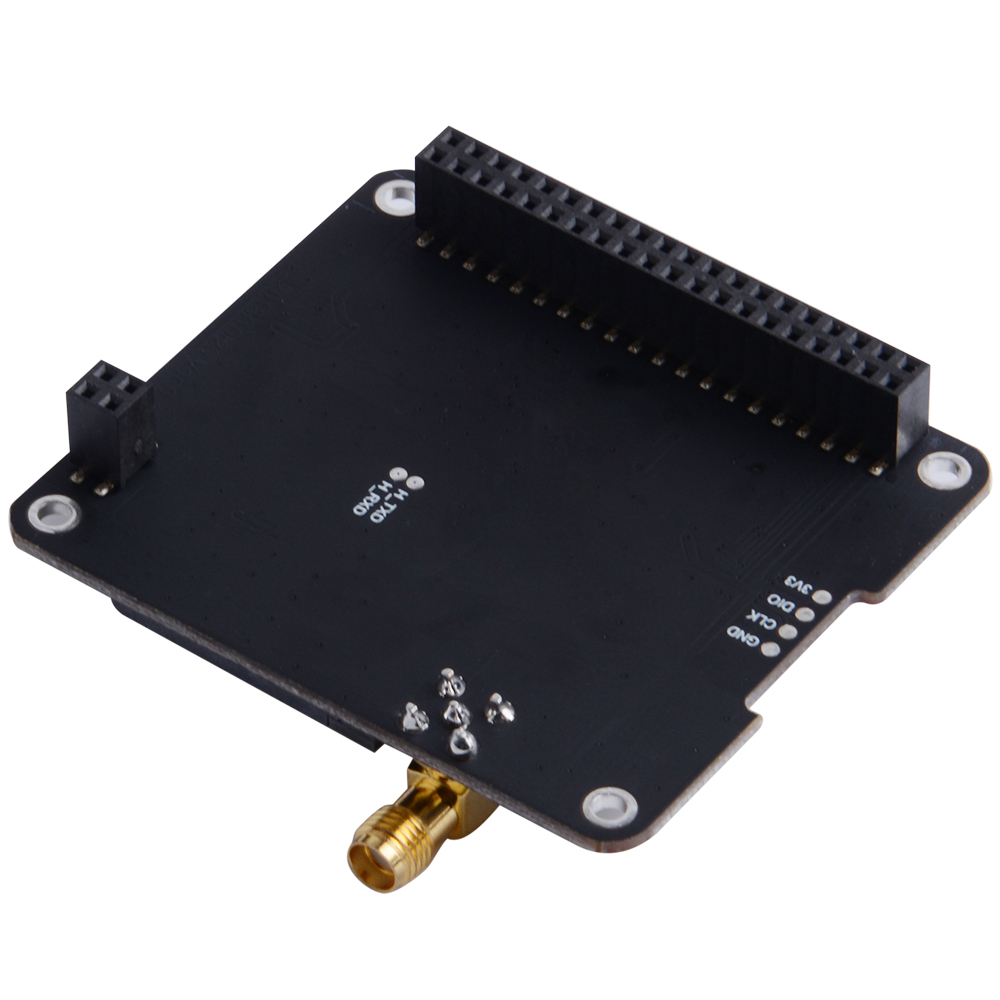
IoT Node(A) is one of Docker Pi series module.
IOT Node(A) = GPS/BDS + GSM + Lora.
I2C directly controls Lora, sends and receives data, controls the GSM/GPS/BDS module through SC16IS752, the mainboard only needs I2C support.Support Raspberry Pi and other similar products.
So you can make a middle range communication device by using two of them.
and also you can locate your device's location by using the GPS module onboard.
Insert a SIM card, It will become a transmitter station via SMS message.
Step2 : How to Assemble It
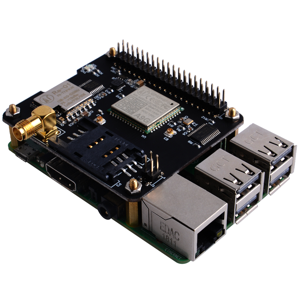
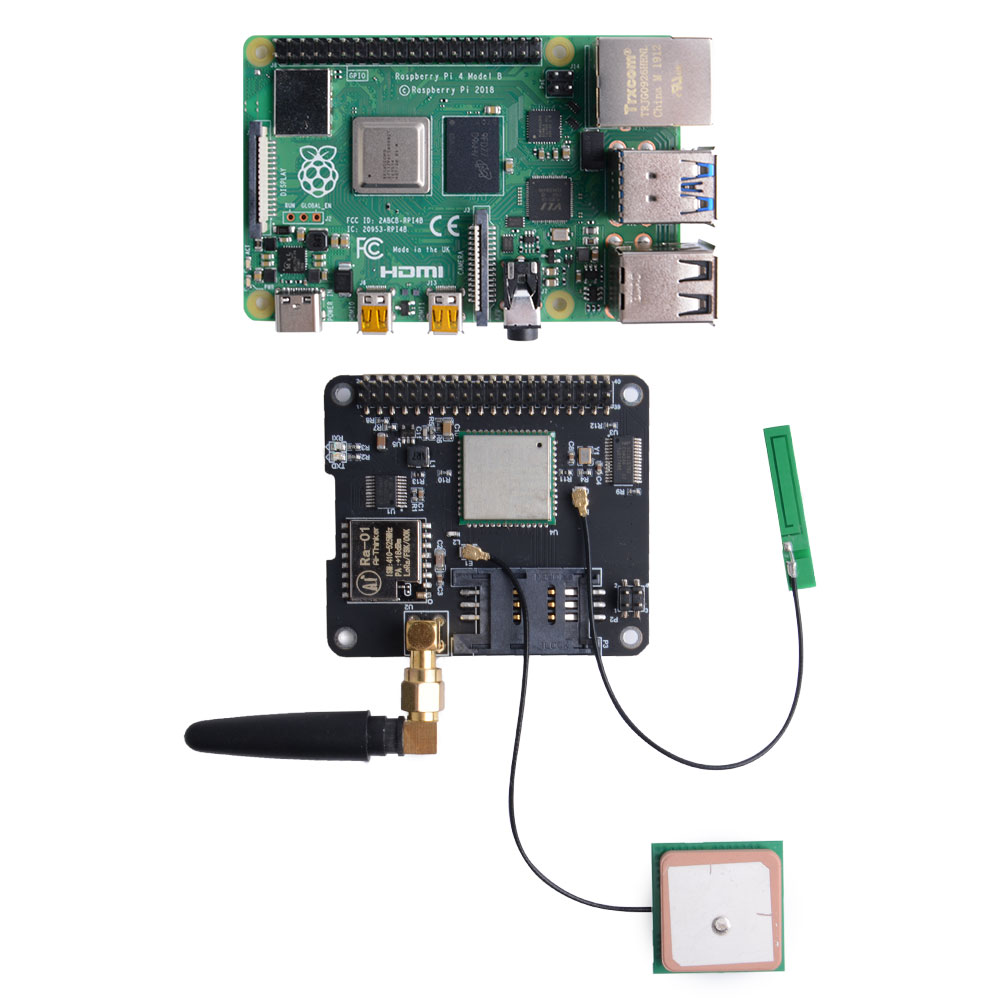
It is very easy to assemble it due to it's "HAT" design, you just put it on your raspberry pi and conncect it via GPIO pins, it like a "hat" on raspberry pi, so that you do not have to add the mass wire.
Step3: Hook Up Antenna
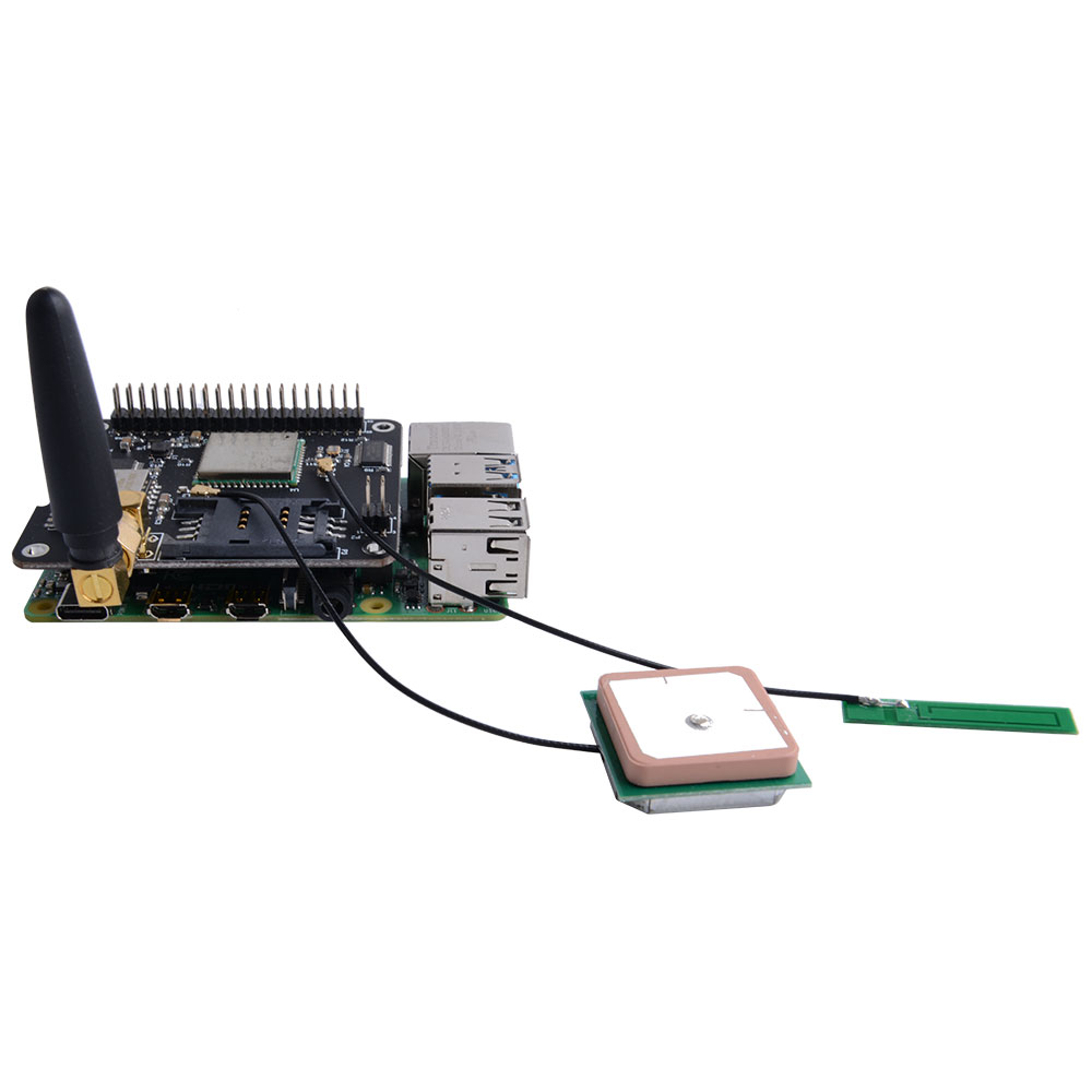
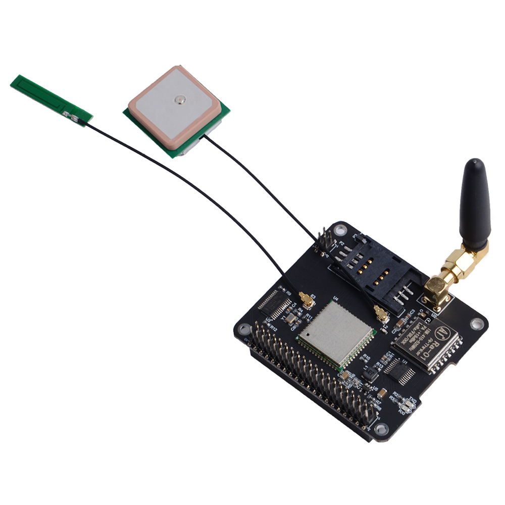
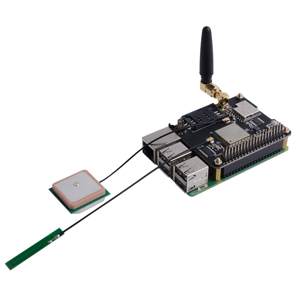
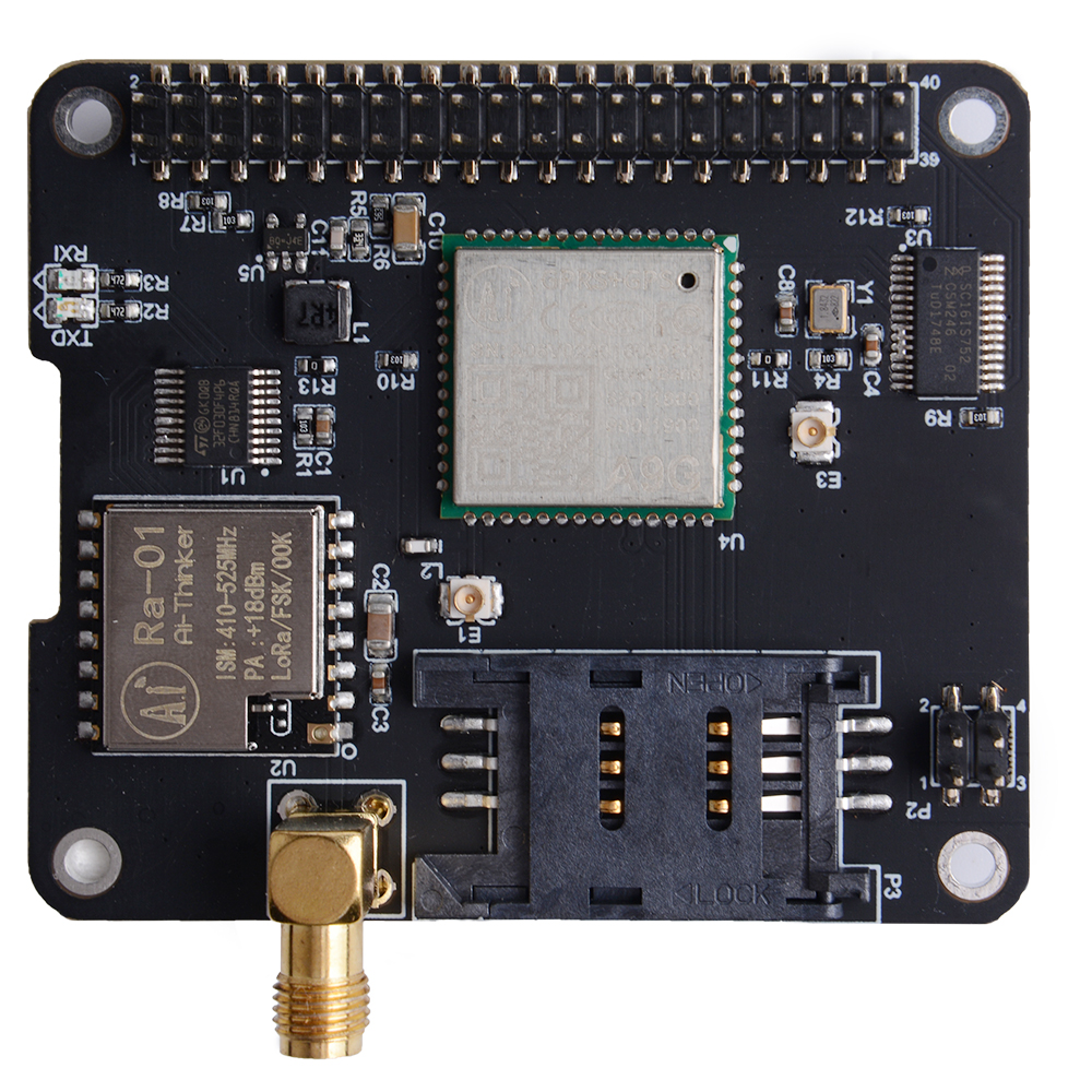
There are 3 pieces antenna for this IoT (A)module , one of them is for the loar module, it is a SMA type antenna, and one of them is good for you GPS , it's a square box antenna which has IPX port. and the last one is for the SIM module(A9G), It's a tiny antenna which has a IPX port. connect the antenna and mount the hat to your raspberry pi.
How to assemble
Mount the Iot Node(A) board to Raspberry Pi
Hookup GPS antana and Lora antana to IPX port.
- E1:GPS-ANTANA-IPX
- E3:LoRa-ANTANA-IPX
Screws the GPRS antana on the SMA port.
Step4: OS Environment and Software Configurations
In this step, you have to do those things :
1. Download the latest image file from : www.raspberrypi.org/downloads
2. Unzip it .
3. Flash your TF card with the latest image via etcher tool
4.Modify the /boot/config.txt file and add this paragraph.
dtoverlay=sc16is752-i2c
5. Replaces /boot/overlay/sc16is752-i2c.dtbo file with this file:
https://wiki.52pi.com/index.php/File:Sc16is752-i2c...
PS : do remember unzip it an put it on your /boot/overlay/ folder and replaces the old one.
6. Reboot your Raspberry Pi.
Step5: Configuring I2C(Raspberry Pi)
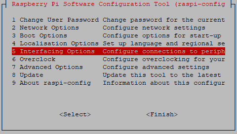
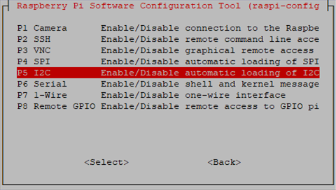
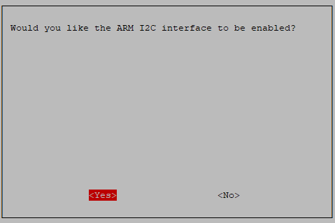
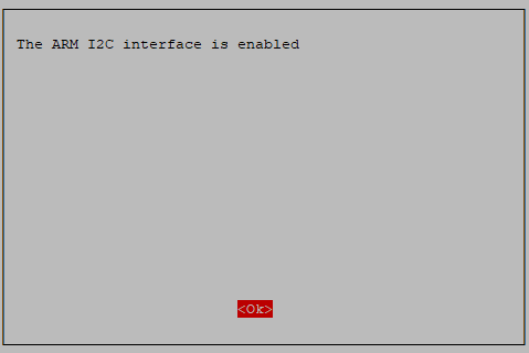
Run sudo raspi-config and follow the prompts to install i2c support for the ARM core and linux kernel Go to Interfacing Options
Step6: Know About the Register Informations
GPRS section
Low power consumption, standby sleep current <1mA2.
Support GSM/GPRS four frequency bands, including 850, 900, 1800, 1900MHZ
GPRS Class 10
Support GPRS data service, maximum data rate, download 85.6Kbps, upload 42.8Kbps
Support standard GSM07.07, 07.05 AT commands, and access the serial port through I2C interface conversion
AT commands support standard AT and TCP/IP command ports
GPS section
Support BDS/GPS joint positioning
Support A-GPS, A-BDS
Support standard SIM card
LORA section
Transmission distance:500 Meters (RF parameters: 0x50 @ China City)
Support FSK, GFSK, MSK, GMSK, LoRaTM and OOK modulation methods
Ultra-high receiver sensitivity as low as -141 dBm
Support preamble detection
Packet engine with CRC, up to 256 bytes
LORA transceiver indicator
Easy TX/RX by Docker Pi
A9G Module
A9G module offers two serial port.
Use I2C <=> UART bridge for communication.
Serial Port Module name
- /dev/ttySC0 GSM
- /dev/ttySC1 GPS/BDS
Register Map
- Register Address Function Value
- 0x01 LORA_TX1 Lora TX Buffer 1 - User Data
- 0x02 LORA_TX2 Lora TX Buffer 2 - User Data
- 0x03 LORA_TX3 Lora TX Buffer 3 - User Data
- 0x04 LORA_TX4 Lora TX Buffer 4 - User Data
- 0x05 LORA_TX5 Lora TX Buffer 5 - User Data
- 0x06 LORA_TX6 Lora TX Buffer 6 - User Data
- 0x07 LORA_TX7 Lora TX Buffer 7 - User Data
- 0x08 LORA_TX8 Lora TX Buffer 8 - User Data
- 0x09 LORA_TX9 Lora TX Buffer 9 - User Data
- 0x0a LORA_TX10 Lora TX Buffer 10 - User Data
- 0x0b LORA_TX11 Lora TX Buffer 11 - User Data
- 0x0c LORA_TX12 Lora TX Buffer 12 - User Data
- 0x0d LORA_TX13 Lora TX Buffer 13 - User Data
- 0x0e LORA_TX14 Lora TX Buffer 14 - User Data
- 0x0f LORA_TX15 Lora TX Buffer 15 - User Data
- 0x10 LORA_TX16 Lora TX Buffer 16 - User Data
- 0x11 LORA_RX1 Lora RX Buffer 1 - User Data
- 0x12 LORA_RX2 Lora RX Buffer 2 - User Data
- 0x13 LORA_RX3 Lora RX Buffer 3 - User Data
- 0x14 LORA_RX4 Lora RX Buffer 4 - User Data
- 0x15 LORA_RX5 Lora RX Buffer 5 - User Data
- 0x16 LORA_RX6 Lora RX Buffer 6 - User Data
- 0x17 LORA_RX7 Lora RX Buffer 7 - User Data
- 0x18 LORA_RX8 Lora RX Buffer 8 - User Data
- 0x19 LORA_RX9 Lora RX Buffer 9 - User Data
- 0x1a LORA_RX10 Lora RX Buffer 10 - User Data
- 0x1b LORA_RX11 Lora RX Buffer 11 - User Data
- 0x1c LORA_RX12 Lora RX Buffer 12 - User Data
- 0x1d LORA_RX13 Lora RX Buffer 13 - User Data
- 0x1e LORA_RX14 Lora RX Buffer 14 - User Data
- 0x1f LORA_RX15 Lora RX Buffer 15 - User Data
- 0x20 LORA_RX16 Lora RX Buffer 16 - User Data
- 0x01 - 0x10 Write Only.
- 0x11 - 0x20 Read Only.
Instructions:
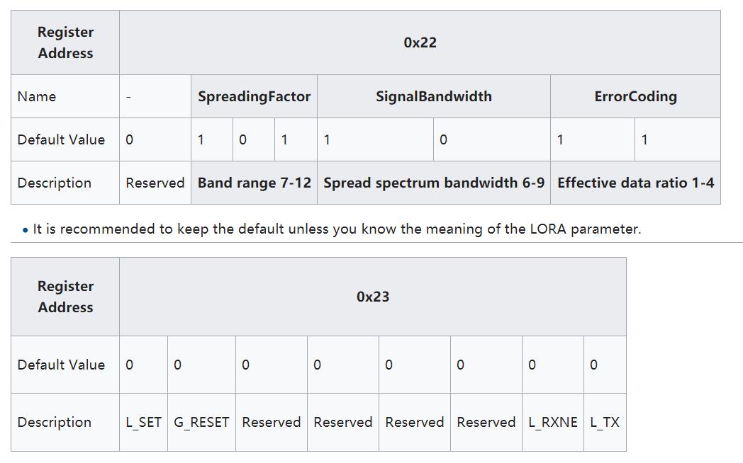
L_SET(Write Only)
- Write 1 to set parameters from 0x22 to LORA Module.
- Write 0 not effect
G_RESET(Write Only)
- Write 1 to reset A9G Module
- Write 0 not effect
L_RXNE(Read & Write)
- Write 1 cause error
- Write 0 to clear
- Read 1 means data has been received, please get the data from the register 0x11 - 0x20.
- Read 0 means no data available now.
L_SET(Write Only)
- Write 1 to send data,please fill in the data in register 0x01 - 0x10 before send.
- Write 0 not effect
How to Use GPS Module With Gpsd(Raspberry Pi)

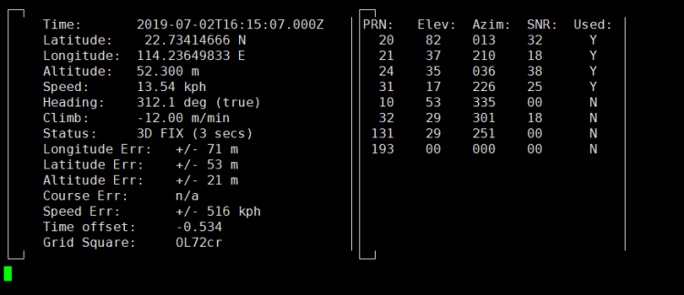
How to use GPS Module with gpsd(Raspberry Pi)
First, replace the /boot/overlays/sc16is752-i2c.dtbo and make sure I2C is working properly.
- Replace sc16is752-i2c.dtbo
- Configuring I2C
- Install gpsd tools.
Open a terminal and typing this command:
sudo apt install gpsd gpsd-clients
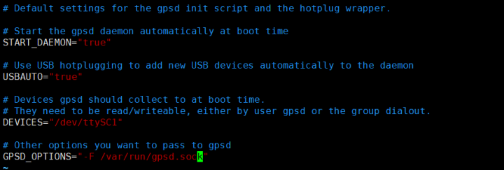
Modify /etc/default/gpsd file and add following parameters:
- DEVICES="/dev/ttySC1"
- GPSD_OPTIONS="-F /var/run/gpsd.sock"
Enter command i2cset -y 1 0x16 0x23 0x40 to reset the GPRS module.
Python Script For Open GPS:
<p>import serial<br>import os
import time
# Restart gpsd service.
os.system("sudo systemctl restart gpsd.socket")
# Open serial port
ser = serial.Serial('/dev/ttySC0', 115200)
i = 0
if ser.isOpen == False:
    ser.open()
try:
    print("Turn on GPS...")
    while True:
        ser.write(str.encode("AT+GPS=1\r"))
        size = ser.inWaiting()
        if size != 0:
            ticks = time.time()
            response = ser.read(size)
            gps = str(response,encoding="utf-8")
            if(gps.find("OK") != -1):
                os.system("sudo cgps -s")
                exit()
            else:
                i = i + 1
                print("Waiting GPS Enable, If the time is too long, Please test outdoors:" + str(i))
                ser.flushInput()
                time.sleep(1)
except KeyboardInterrupt:
    ser.flushInput()
    ser.close()</p>
Save it and execute it:
python3 GPS.py
How to Use GPS Module With C(Raspberry Pi)
Install gpsd tools.
sudo apt-get install libgps-dev
Create source code and name it "gps.c"
<p>#include <gps.h><br>#include <stdio.h>
#include <stdlib.h></p><p>#include <unistd.h>
#include <math.h>
</p><p>int main()
{
   int rc;
   struct timeval tv;
   struct gps_data_t gps_data;
   if ((rc = gps_open("localhost", "2947", &gps_data)) == -1)
   {
      printf("code: %d, reason: %s\n", rc, gps_errstr(rc));
      return EXIT_FAILURE;
   }

   gps_stream(&gps_data, WATCH_ENABLE | WATCH_JSON, NULL);</p><p>   while (1)
   {
      /* wait for 2 seconds to receive data */
      if (gps_waiting(&gps_data, 2000000))
      {
         /* read data */
         if ((rc = gps_read(&gps_data)) == -1)
         {
            printf("error occured reading gps data. code: %d, reason: %s\n", rc, gps_errstr(rc));
         }
         else
         {
            /* Display data from the GPS receiver. */
            if ((gps_data.status == STATUS_FIX) && (gps_data.fix.mode == MODE_2D || gps_data.fix.mode == MODE_3D) && !isnan(gps_data.fix.latitude) && !isnan(gps_data.fix.longitude))
            {
               /* gettimeofday(&tv, NULL); EDIT: tv.tv_sec isn't actually the timestamp! */</p><p>               printf("latitude: %f, longitude: %f, speed: %f, timestamp: %lf\n", gps_data.fix.latitude, gps_data.fix.longitude, gps_data.fix.speed, gps_data.fix.time);
               //EDIT: Replaced tv.tv_sec with gps_data.fix.time
            }
            else
            {
               printf("no GPS data available\n");
            }
         }
      }
      sleep(3);
   }
   /* When you are done... */
   gps_stream(&gps_data, WATCH_DISABLE, NULL);
   gps_close(&gps_data);
   return EXIT_SUCCESS;
}</p>
Compile It.
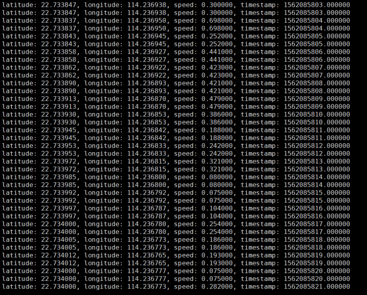
Compile!
gcc gps.c -lm -lgps -o gps
Exec It!
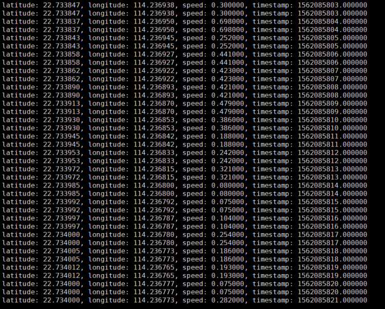
./gps
How to Use GPS Module With Python(Raspberry Pi)

The following code is recommended to be executed using Python 3 and install the gpsd-py3 library and GPS 2D/3D Fix:
import gpsd
# Connect to the local gpsd
gpsd.connect()
# Get gps position
packet = gpsd.get_current()
# See the inline docs for GpsResponse for the available data
print(packet.position())
How to Use GSM Module With PPPd(Raspberry Pi)
A) First, replace the /boot/overlays/sc16is752-i2c.dtbo and make sure I2C is working properly.
- Replace sc16is752-i2c.dtbo
- Configuring I2C
B)Enter command i2cset -y 1 0x16 0x23 0x40 to reset the GPRS module.
After running the command, you need to wait a little, about 10 seconds
You can also use the following method to reset.
C)Enter command
<strong>sudo apt install ppp </strong>
to install ppp tools.
D)Copy /etc/ppp/peers/provider to /etc/ppp/peers/gprs
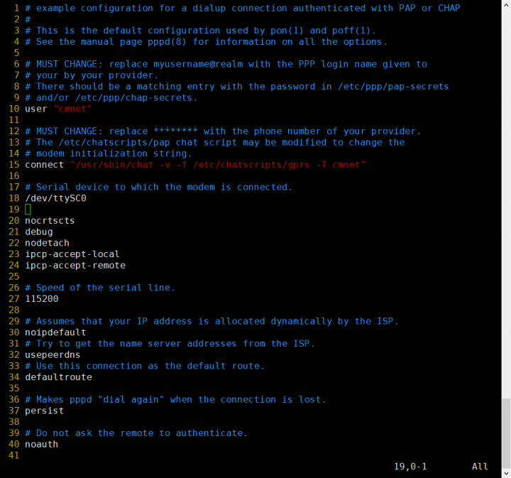
E)Modify /etc/ppp/peers/gprs
- Line 10 : Please consult your service provider for the user (Example:cmnet).
- Line 15 : Please consult your service provider for the apn (Example:cmnet).
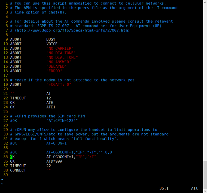
- Line 18 - Line 24:Recommended setting
F)Modify /etc/chatscripts/gprs (Change Line 34 to Line 35,Dialout Number May be NOT *99#)
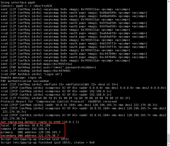
G)Enter command sudo pppd call gprs to dial up.
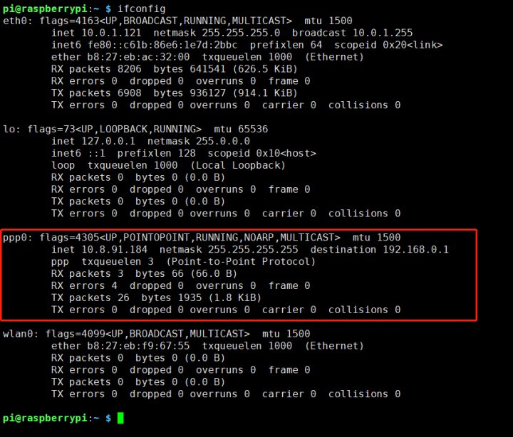
H)Check your ppp config from your ISP.
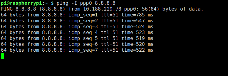
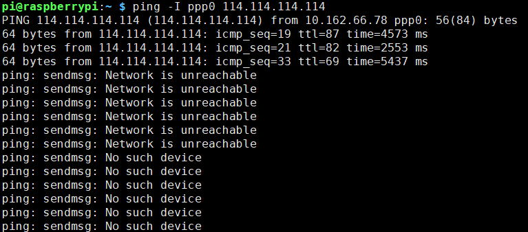
I)Enter command ping -I ppp0 8.8.8.8 test your network (If Internet available and route table is correct)
J)Please keep the GSM signal good, otherwise the following will occur.
How to Diagnose My GSM Module(Raspberry Pi)
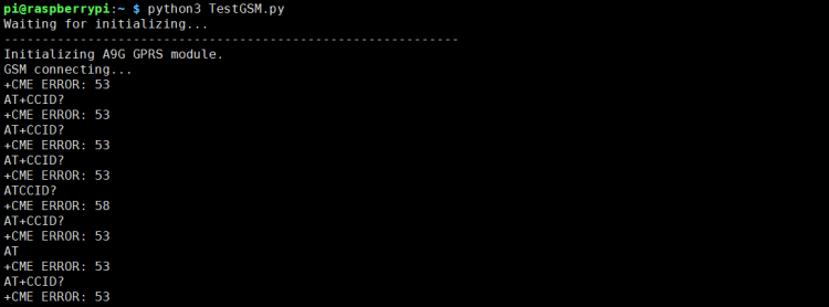
The following code is recommended to be executed using Python 3 and install the smbus library:
import serial
import time import smbus import operator import osprint("Waiting for initializing...")
bus = smbus.SMBus(1) bus.write_byte_data(0x16,0x23,0x40)
ser = serial.Serial('/dev/ttySC0', 115200)
if ser.isOpen == False: ser.open() try: print('-'*60) print("Initializing A9G GPRS module.") print("GSM connecting...") time.sleep(3) i = 0 while True: ser.write(str.encode("AT+CCID\r")) size = ser.inWaiting() if size != 0: ticks = time.time() response = ser.read(size) ccid = str(response,encoding="utf-8") print(ccid) else: i = i + 1 ser.flushInput() time.sleep(1) except KeyboardInterrupt: ser.close()
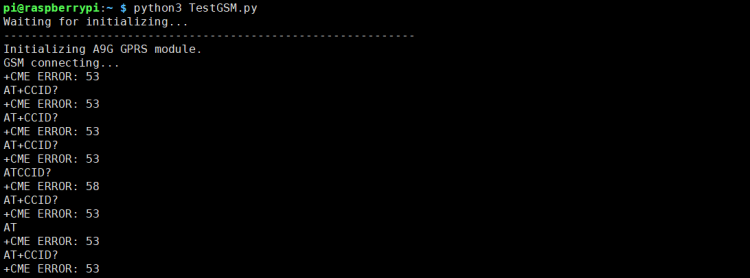
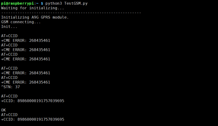
Exec the Test Script,based on the results of the implementation, we can diagnose the GSM module.
For example, the following return, CME ERROR 53 error tell us Power not good. CME Code = GSM Equipment Related errors
Of course, the script also has a reset function. If you can display the CCID correctly, the reset is complete.
How to Use Lora TX & RX With C(Raspberry Pi)
The following code is recommended to be executed using Python 3 and install the smbus library.
It must be transferred between the two IOT Node(A). The content sent by itself cannot be received by itself. Please save it as a py script for execution.
How to Send:After filling the data into register 0x01 - 0x10, set the L_TX bit to start sending data.
import time
import smbus
import os
import sysbus = smbus.SMBus(1)    try:
    data_list = [170,85,165,90]

    # write data to register and then the data will be send out.
    for index in range(1,len(data_list) + 1):
        bus.write_byte_data(0x16,index,data_list[index - 1])
        print("LORA send data to %d register %d data" %(index, data_list[index - 1]))

    bus.write_byte_data(0x16,0x23,0x01)
except KeyboardInterrupt:
    sys.exit()
- How to Send Receive:Check L_RXNE bit,If set,new data arrived,this flag must be manually clear.
import time
import smbus
import os
import sysbus = smbus.SMBus(1)
recv_data = [] try:
    if bus.read_byte_data(0x16,0x23) & 0x02 :
        # manually clear L_RXNE
        bus.write_byte_data(0x16,0x23,0x00)
        register_list = [0x11,0x12,0x13,0x14]

        # read out data
        for index in range(0x11,len(register_list) + 0x11):
            recv_data.append(bus.read_byte_data(0x16, register_list[index - 0x11]))        print("Received data:")
        print(recv_data)
    else :
        print("No data Received yet~")
except KeyboardInterrupt:
    sys.exit()
Special Description of I2C Bandwidth
The limit of the I2C speed is 400kHz,due to the I2C protocol,so the single device effective bandwidth is lower than 320kbps,multi device effective bandwidth is lower than 160kbps.The limit of the I2C <=> UART Bridge speed is 115200bps.When GPS and GSM work at the same time, I2C bandwidth is insufficient,because 115.2kbps * 2 = 230.4kbps,so some data will be overflow.Reducing the baud rate of GPS and GSM communication can improve the communication bandwidth shortage.Stacking other DockerPi modules may take up extra I2C bandwidth.At usually, the network data speed is slow, so the GSM bandwidth is not full, so there is no overflow problem.
Finished
Hope you guys like it and make it.
you can find it here:
Amazon
Nightlight:https://www.amazon.com/GeeekPi-Night-Light-WS2812-Raspberry/dp/B07LCG2S5S 4channel Relay board: https://www.amazon.co.uk/dp/B07MV1TJGR?ref=myi_title_dp Power Board:https://www.amazon.co.uk/dp/B07TD595VS?ref=myi_title_dp IoT Node(A):https://www.amazon.co.uk/dp/B07TY15M1C Sensor HUB: https://www.amazon.co.uk/dp/B07TZD8B61 ice tower: https://www.amazon.com/dp/B07V35SXMC?ref=myi_title_dp