Diy NRF Test
.png)
.png)
If you have hard-time 3d printing stuff and other materials which i have provided in this project please refer the professionals for the help, JLCPCB is one of the best company from shenzhen china they provide, PCB manufacturing, PCBA and 3D printing services to people in need, they provide good quality products in all sectors
Please use the following link to register an account in JLCPCB
Pcb Manufacturing
----------
2 layers
4 layers
6 layers
PCBA Services
JLCPCB have 350k+ Components In-stock. You don’t have to worry about parts sourcing, this helps you to save time and hassle, also keeps your costs down.
Moreover, you can pre-order parts and hold the inventory at JLCPCB, giving you peace-of-mind that you won't run into any last minute part shortages. jlcpcb.com/RNA
3d printing
-------------------
SLA -- MJF --SLM -- FDM -- & SLS. easy order and fast shipping makes JLCPCB better companion among other manufactures try out JLCPCB 3D Printing servies
JLCPCB 3D Printing starts at $1 &Get $54 Coupons for new users
Supplies
.png)
.png)
For explaining the wireless communication we will make two examples, the first one will be sending a simple “Hello World” message from one Arduino to another, and in the second example we will have a bi-directional communication between the Arduino boards, where using the Joystick at the first Arduino we will control the servo motor at the second Arduino, and vice versa, using the push button at the second Arduino we will control the LED at the first Arduino.
Let’s take a closer look at the NRF24L01 transceiver module. It uses the 2.4 GHz band and it can operate with baud rates from 250 kbps up to 2 Mbps. If used in open space and with lower baud rate its range can reach up to 100 meters.
The power consumption of this module is just around 12mA during transmission, which is even lower than a single LED. The operating voltage of the module is from 1.9 to 3.6V, but the good thing is that the other pins tolerate 5V logic, so we can easily connect it to an Arduino without using any logic level converters. Three of these pins are for the SPI communication and they need to be connected to the SPI pins of the Arduino, but note that each Arduino board has different SPI pins. The pins CSN and CE can be connected to any digital pin of the Arduino board and they are used for setting the module in standby or active mode, as well as for switching between transmit or command mode. The last pin is an interrupt pin which doesn’t have to be used.
The second variation, instead of on-board antenna, it has a SMA connector and which we can attach a duck antenna for better transmission range.
The third variation shown here, in addition to the duck antenna, it has a RFX2401C chip which includes PA (Power Amplifier) and LNA (Low-Noise Amplifier). This amplifies the NRF24L01 signal and enables even better transmission range of up to 1000 meters in open space.
.png)
.png)
// at the Transmitter
radio.openWritingPipe(addresses[1]); // 00001
radio.openReadingPipe(1, addresses[0]); // 00002
Code language: Arduino (arduino)
// at the Receiver
radio.openWritingPipe(addresses[0]); // 00002
radio.openReadingPipe(1, addresses[1]); // 00001
Code language: Arduino (arduino)
In the loop section using the radio.stopListening() function we set the first Arduino as transmitter, read and map the value of Joystick from 0 to 180, and using the radio.write() function send the data to the receiver.
radio.stopListening();
int potValue = analogRead(A0);
int angleValue = map(potValue, 0, 1023, 0, 180);
radio.write(&angleValue, sizeof(angleValue));
Code language: Arduino (arduino)
On the other side, using the radio.startListening() function we set the second Arduino as receiver and we check whether there is available data. While there is data available we will read it, save it to the “angleV” variable and then use that value to rotate the servo motor.
radio.startListening();
  if ( radio.available()) {
    while (radio.available()) {
      int angleV = 0;
      radio.read(&angleV, sizeof(angleV));
      myServo.write(angleV);
    }
Code language: Arduino (arduino)
Next, at the transmitter, we set the first Arduino as receiver and with an empty “while” loop we wait for the second Arduino the send data, and that’s the data for the state of the push button whether is pressed or not. If the button is pressed the LED will light up. So these process constantly repeats and both Arduino boards are constantly sending and receiving data.
.png)
.png)
Once we connect the NRF24L01 modules to the Arduino boards we are ready to make the codes for both the transmitter and the receiver.
First we need to download and install the RF24 library which makes the programming less difficult. We can also install this library directly from the Arduino IDE Library Manager. Just search for “rf24” and find and install the one by “TMRh20, Avamander”.
Here are the two codes for the wireless communication and below is the description of them.
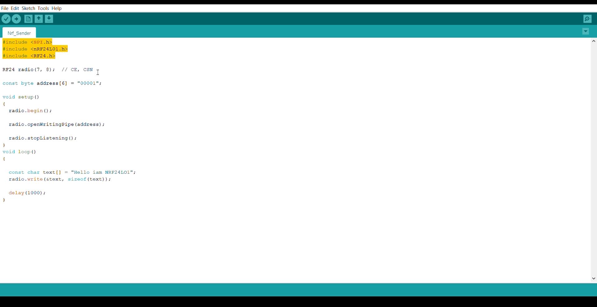
Transmitter Code
#include <SPI.h>
#include <nRF24L01.h>
#include <RF24.h>

RF24 radio(7, 8); // CE, CSN

const byte address[6] = "00001";

void setup() {
  radio.begin();
  radio.openWritingPipe(address);
  radio.setPALevel(RF24_PA_MIN);
  radio.stopListening();
}

void loop() {
  const char text[] = "Hello World";
  radio.write(&text, sizeof(text));
  delay(1000);
}
Receiver Code
#include <SPI.h>
#include <nRF24L01.h>
#include <RF24.h>

RF24 radio(7, 8); // CE, CSN

const byte address[6] = "00001";

void setup() {
  Serial.begin(9600);
  radio.begin();
  radio.openReadingPipe(0, address);
  radio.setPALevel(RF24_PA_MIN);
  radio.startListening();
}

void loop() {
  if (radio.available()) {
    char text[32] = "";
    radio.read(&text, sizeof(text));
    Serial.println(text);
  }
}
.png)
.png)
.png)
RF24 radio(7, 8); // CE, CSN
Code language: Arduino (arduino)
Next we need to create a byte array which will represent the address, or the so called pipe through which the two modules will communicate.
const byte address[6] = "00001";
Code language: Arduino (arduino)
We can change the value of this address to any 5 letter string and this enables to choose to which receiver we will talk, so in our case we will have the same address at both the receiver and the transmitter.
In the setup section we need to initialize the radio object and using the radio.openWritingPipe() function we set the address of the receiver to which we will send data, the 5 letter string we previously set.
radio.openWritingPipe(address);
Code language: Arduino (arduino)
On the other side, at the receiver, using the radio.setReadingPipe() function we set the same address and in that way we enable the communication between the two modules.
radio.openReadingPipe(0, address);
Code language: Arduino (arduino)
Then using the radio.setPALevel() function we set the Power Amplifier level, in our case I will set it to minimum as my modules are very close to each other.
radio.setPALevel(RF24_PA_MIN);
Code language: Arduino (arduino)
Note that if using a higher level it is recommended to use a bypass capacitors across GND and 3.3V of the modules so that they have more stable voltage while operating.
Next we have the radio.stopListening() function which sets module as transmitter, and on the other side, we have the radio.startListening() function which sets the module as receiver.
// at the Transmitter
radio.stopListening();
Code language: Arduino (arduino)
// at the Receiver
radio.startListening();
.png)
.png)
In the loop section, at the transmitter, we create an array of characters to which we assign the message “Hello World”. Using the radio.write() function we will send that message to the receiver. The first argument here is the variable that we want to be sent.
void loop() {
 const char text[] = "Hello World";
 radio.write(&text, sizeof(text));
 delay(1000);
}
Code language: Arduino (arduino)
By using the “&” before the variable name we actually set an indicating of the variable that stores the data that we want to be sent and using the second argument we set the number of bytes that we want to take from that variable. In this case the sizeof() function gets all bytes of the strings “text”. At the end of the program we will add 1 second delay.
Using the radio.write() function we can send maximum of 32 bytes at a time.
On the other side, at the receiver, in the loop section using the radio.available() function we check whether there is data to be received. If that’s true, first we create an array of 32 elements, called “text”, in which we will save the incoming data.
void loop() {
  if (radio.available()) {
    char text[32] = "";
    radio.read(&text, sizeof(text));
    Serial.println(text);
  }
}
Code language: Arduino (arduino)
Using the radion.read() function we read and store the data into the “text” variable. At the end we just print text on the serial monitor. So once we upload both programs, we can run the serial monitor at the receiver and we will notice the message “Hello World” gets printed each second.
Troubleshooting
It’s worth noting that power supply noise is one of the most common issues people experience when trying to make successful communication with the NRF24L01 modules. Generally, RF circuits or radio frequency signals are sensitive to power supply noise. Therefore, it’s always a good idea to include a decoupling capacitor across the power supply line. The capacitor can be anything from 10uF to 100uF.
.png)
.png)
.png)
These are the 2.4GHz NRF24L01 Transceiver modules. These transceiver modules operate in the 2.4GHz band and have many new features including extra pipelines, buffers, and an auto-retransmit feature.
This board features a reverse polarized SMA connector for maximum RF range; and there is the PA and LNA circuit on board, with the external antenna it can reach long distance than the one without these parts.
This module comes with the 2.4G antenna, with a 250Kbps transmission rate, on open-air it can reach the 800 to 1K meters communication distance.
.png)
.png)
- CSNstands for chip select not. This is the enable pin for the SPI bus, and it is active low (hence the “not” in the name). You always want to keep this pin high except when you are sending the device an SPI command or getting data on the SPI bus from the chip. When this pin goes low, the 24L01 begins listening on its SPI port for data and processes it accordingly.
- SCKis the serial clock for the SPI bus. When you configure your SPI bus, SCK should stay low normally (rising edges are active), and the clock samples data in the middle of data bits.
- MOSIstands for “master out, slave in,” and from both the microcontroller’s and the 24L01’s perspectives, the master is the microcontroller and the slave is the 24L01. This is because the 24L01 never sends data without first being requested by the microcontroller. Essentially, this pin is the side of the bus on which the master (the microcontroller) sends data to the slave (the 24L01). It is also connected to the MOSI pin on your microcontroller’s SPI interface.
- MISOpin is like the MOSI pin, but backwards. This pin is the side of the bus on which the slave (the 24L01) sends data to the master (the microcontroller).
- IRQis the interrupt pin and is active-low. There are three internal interrupts that can cause this pin to go low when they are active.
This time I made a few changes, I defined pins for the potentiometers and a pushbutton.
I Defined an array data of the type byte.
Inside the void setup() function, I set the potentiometers and the pushbutton as the input.
Inside the void loop() function, we simply read the potentiometers and store the mapped values in the array at different locations.
if(digitalRead(Pushbutton) == LOW)
{
data[3] = 1;
}
if(digitalRead(Pushbutton) == HIGH)
{
data[3] = 0;
}
radio.write( data, sizeof(data) );
}
These two conditions are used if the pushbutton is pressed or not. If the pushbutton is pressed then a value of 1 is stored in the array at location 3, and if the pushbutton is not pressed then a value of 0 is stored.
As usual, I started off by adding the libraries.
Next, I defined pins for the CE and CSN.
const uint64_t pipe = 0xE8E8F0F0E1LL;
This is a unique pipe address; this should be the same on the Transmitter and Receiver side.
char data[] = “Hello World, Electronic Clinic”;
I defined an array of the type character which is used to store the message. In my case, I want to send the “Hello World, Electronic Clinic” message.
Inside the void setup() function, I activated the Serial communication and selected 9600 as the baud rate and finally, activated the radio communication.
radio.write( data, sizeof(data) );
The left and right legs of all the three potentiometers are connected with the Arduino’s 5 volts and ground, while the middle legs are connected with the Arduino’s analog pins A0, A1, and A2. For the demonstration purpose
The receiver programming is almost the same. Inside the void loop() function we simply print the received data on the serial monitor.
If the communication is lost for 1 second then a message “Connection Lost” will be printed on the Serial Monitor.
I was able to monitor all the three potentiometers in real-time. I also checked the Pushbutton. These potentiometers can be replaced with different analog sensors. Digital Sensors can be added with the other I/O pins of the Arduino Uno.
Inside the void loop function, we have only one instruction, which is used to send the message.