Diy Game Using Arduino and Nokia 5110 Lcd
by engineerkid1 in Circuits > Arduino
2841 Views, 2 Favorites, 0 Comments
Diy Game Using Arduino and Nokia 5110 Lcd
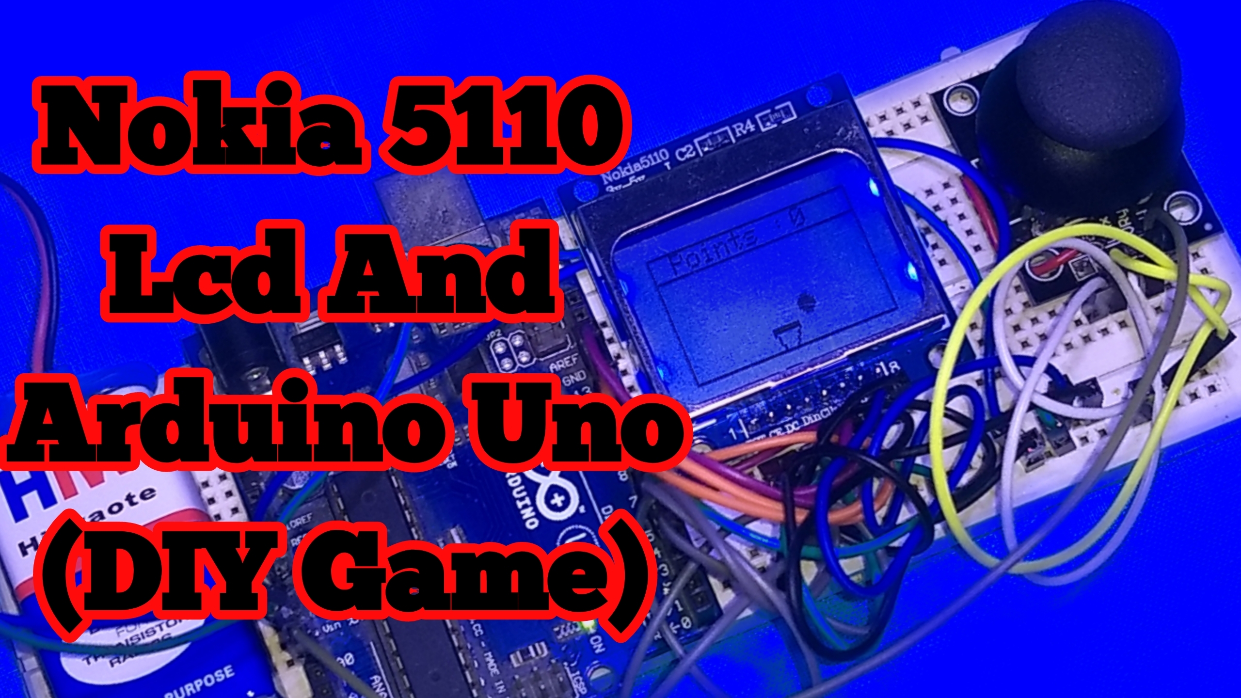
Hello everyone, I'm Sarvesh an electronics hobbyist who loves to make fun projects using arduino and other micro-controllers. Today we will learn the interfacing of a Nokia 5110 lcd to an arduino board and then we will create a simple game to catch the eggs in a bucket and control the movements of the bucket using a joystick module. So read the complete instructable and try making this project. Let's get started !!!
Get the Supplies
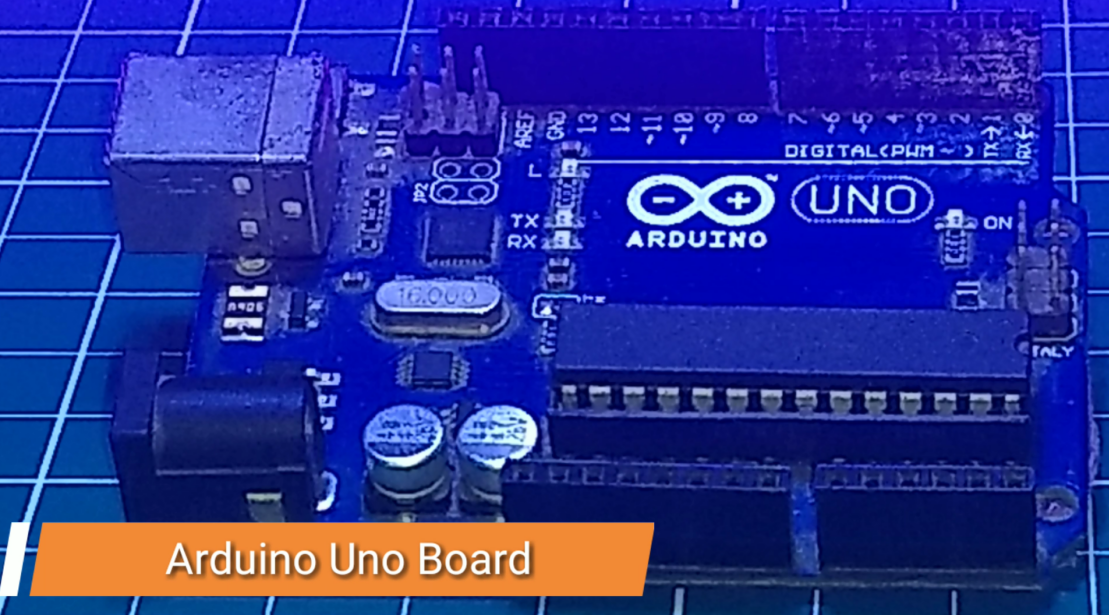
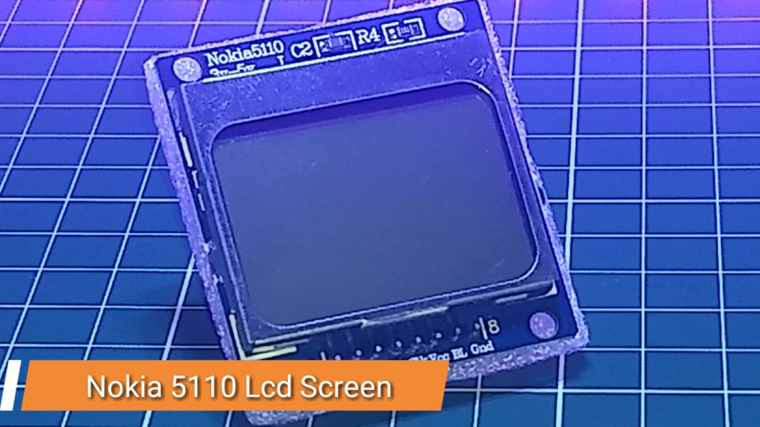
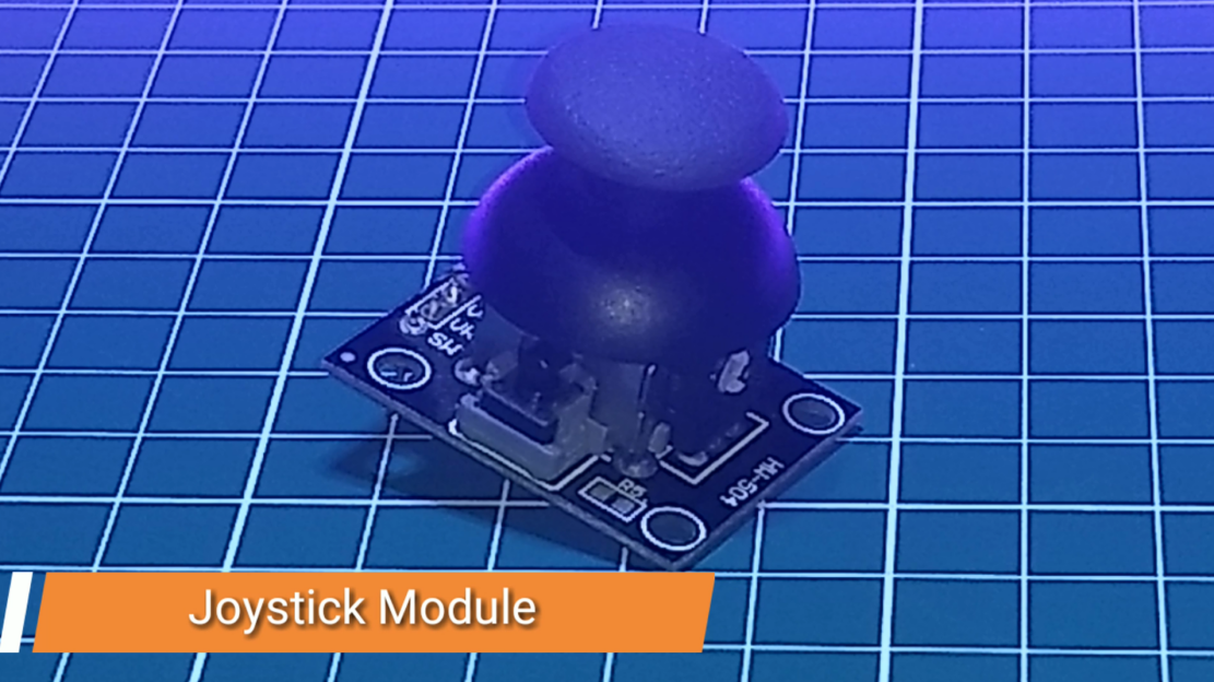
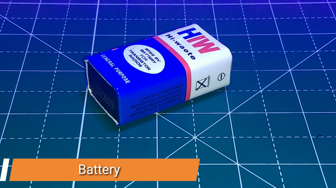
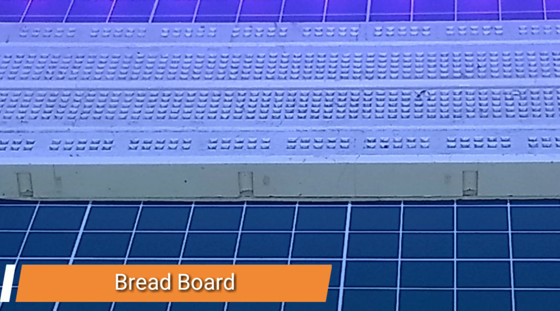
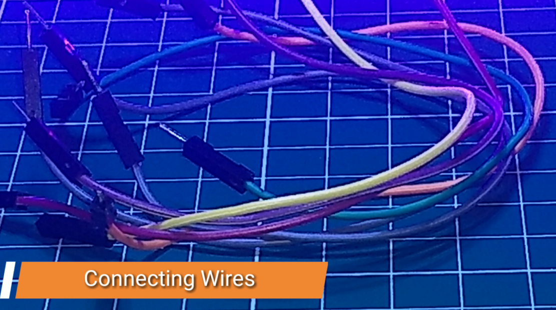
I recommend you to buy the components from UTSource.net as they provide low cost electronics components and modules with no compromise in quality. Also they deliver the products on time. Do check them out!!!
For this project we will need the following components -
1 x Arduino Uno
1 x Nokia 5110 Lcd Screen
1 x Joystick Module
9 Volt Battery
Breadboard
Connecting Wires
Circuit Diagram & First Test
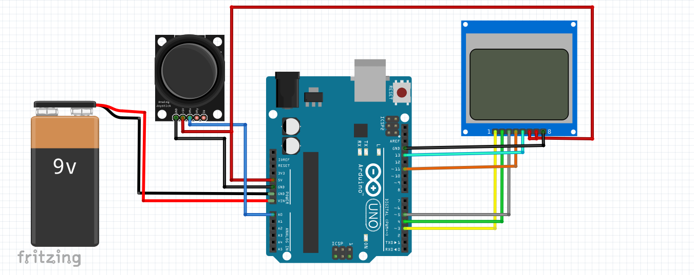
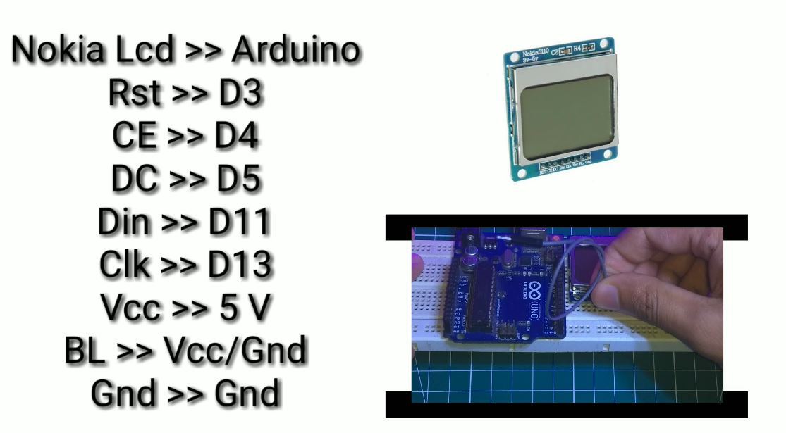
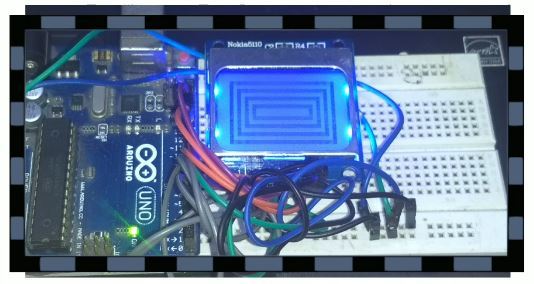
Now connect the lcd screen to the arduino board as shown in the diagram above. Refer the second image for more help with the connections. If you are using this screen first time and don't know how to code it, then you can download the PCD library from the arduino libraries or you can click the link by clicking here.
You also need the adafruit GFX library.
Now open the PCD.test sketch from the examples and upload it to your board. You should see various patterns on your screen.
If you don't see anything on the screen, then check the supply voltage rating of your screen. Mine was 5 V so I had no problems. If still it does not turn on then check the connections.
Note : In the pcd.test example, you can connect your nokia screen to either the software SPI pins or the Hardware SPI pins. I used the hardware SPI pins.
You can see the test output in the third image above.
Coding
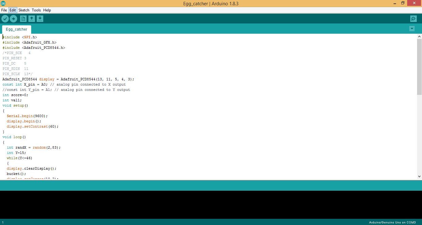
Now open the sketch given above. Compile and upload it to the Arduino Board. You can copy the code from here.
#include
#include
#include
/*PIN_SCE   4
PIN_RESET 3
PIN_DC    5
PIN_SDIN  11
PIN_SCLK  13*/
Adafruit_PCD8544 display = Adafruit_PCD8544(13, 11, 5, 4, 3);
const int X_pin = A0; // analog pin connected to X output
//const int Y_pin = A1; // analog pin connected to Y output
int score=0;
int val1;
void setup()
{
  Serial.begin(9600);
  display.begin();
  display.setContrast(60);
}
void loop()
{
  int randX = random(2,83);
  int Y=15;
  while(Y<=46)
  {
  display.clearDisplay();
  bucket();
  display.setCursor(10,2);
  display.println("Points : ");
  display.setCursor(60,2);
  display.println(score);
  display.fillCircle(randX, Y, 3, BLACK);
  display.drawRect(1, 1, 83, 47, BLACK);
  display.drawLine(1, 10, 83, 10, BLACK);
  display.display();
  delay(80);
  Y=Y+1;
  if(val1>=randX-2 && val1<=randX+2 && Y>=40)
  {
    Y=48;
    score=score+1;
    display.setCursor(60,2);
    display.println(score);
  }
  else if(Y==47)
  {
    score=0;
  }
  }
}
void bucket()
{
  display.clearDisplay();
  val1 = analogRead(X_pin);
  val1 = map(val1, 0, 1014, 0, 83);
  //val2 = analogRead(Y_pin);
  //val2 = map(val2, 0, 1014, 0, 47);
  display.drawLine(val1-5, 40, val1+5, 40, BLACK);
  display.drawLine(val1-5, 39, val1+5, 39, BLACK);
  display.drawLine(val1-5, 40, val1-3, 46, BLACK);
  display.drawLine(val1+5, 40, val1+2, 46, BLACK);
  display.display();
  //Serial.println(val1);
  //Serial.print(val2);
}
Before uploading the code don't forget to connect the joystick to analog pin A0. Now connect the Battery to the Arduino to power it and the project is ready.
Downloads
Working of the Project
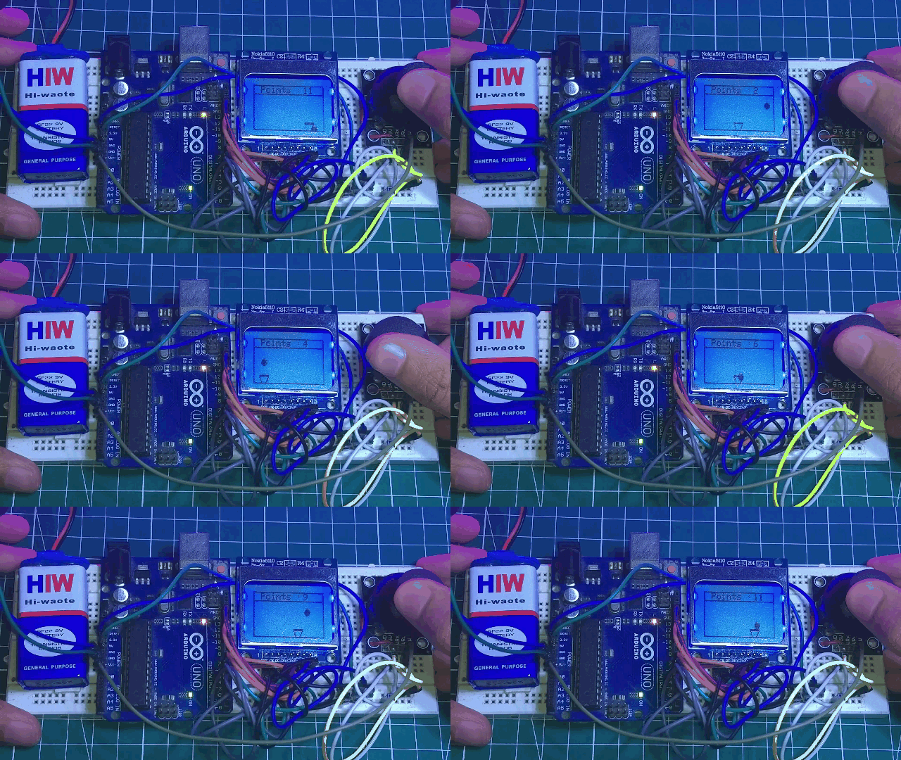
I have attached two files above showing the working of the project. If you liked this instructable then please share it with your friends. If you have any doubts related to the code then please drop a comment below. I will try my best to help you out. That's it for today guys. See you'll in another instructable soon. Thank you.