Diving Helmet Touch Lamp
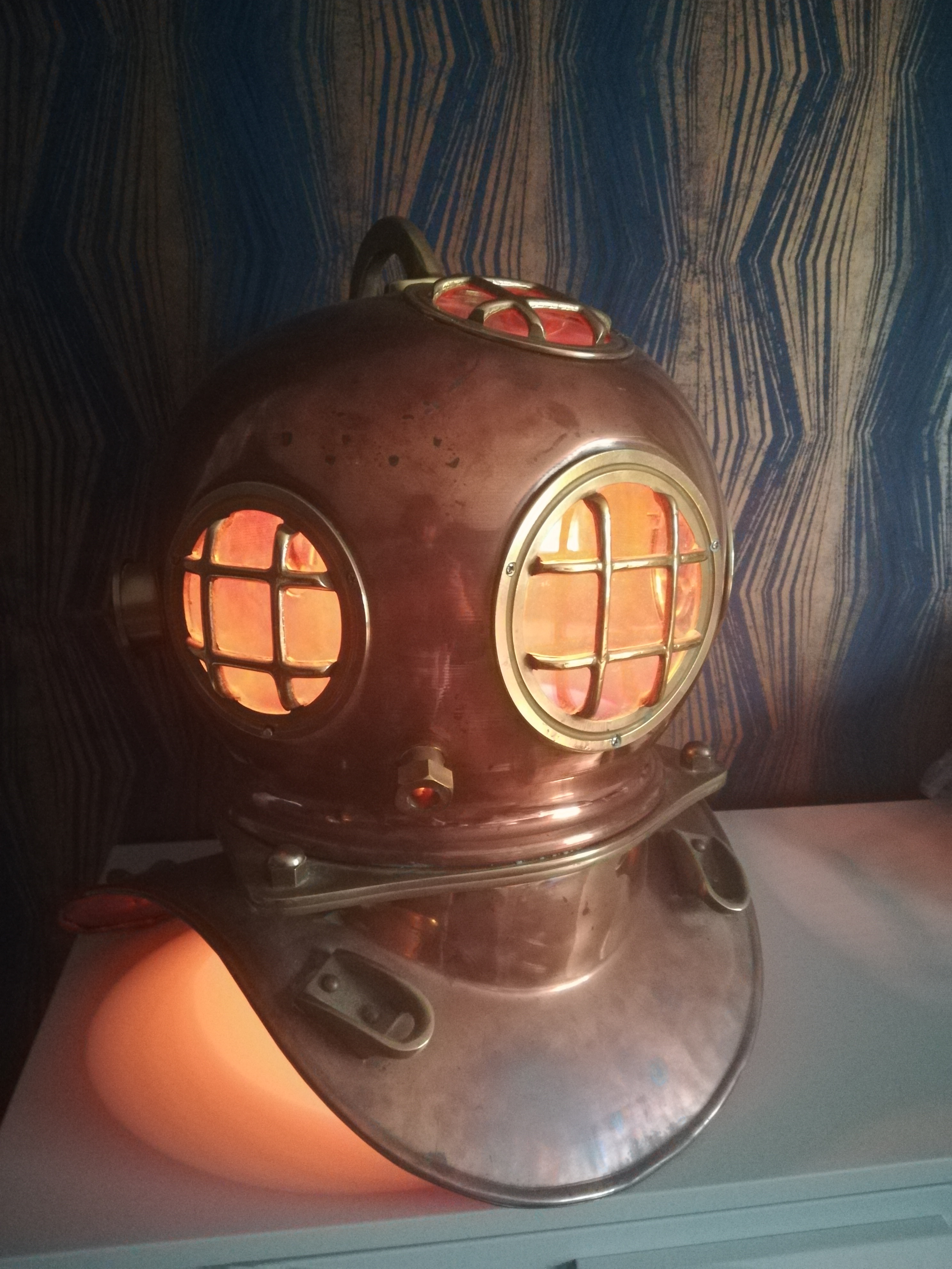
In this instructable
You will need
- Diving helmet or equivalent
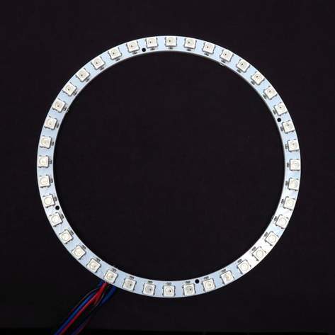
- Neopixel compatible LED ring (I used a ring with 38 LEDs)
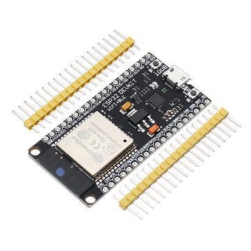
- Wemos ESP32 board (or equivalent)
- 3D printer
Print These Parts
These parts may need adapting if you are using a different diving helmet, I learned that the one I have is fairly common
Upload the Code
Place your ssid and password into the code then upload to your board. This is there to allow OTA uploading new code after the project is assembled. You will need to install NeoPixelBus by Makuna available here https://github.com/Makuna/NeoPixelBus You will also need to install the ESP32 board definitions into the arduino environment in order to use this board.
//Wifi Jazz
#include
#include
#include
#include

bool wifi_timout = 0;
const char* ssid = "SSID";
const char* password = "Password";

//Neopixel jazz
#include
const uint16_t PixelCount = 38;
const uint8_t PixelPin = 19;

int colorSaturation = 50;
int Brightness = 50;
int R = 0;
int G = 0;
int B = 0;
int Pulse = 1600; //Half the time between pulsations
RgbColor black(0);

//Button Jazz
float Button1_total = 0;
int smoothing = 50;
const int debounce = 5;
float Button1[debounce];
bool PWR = 0;

NeoPixelBus ring(PixelCount, PixelPin);


void setup() {
  Serial.begin(115200);
  Serial.println("Booting");
  WiFi.mode(WIFI_STA);
  WiFi.begin(ssid, password);
  while (WiFi.waitForConnectResult() != WL_CONNECTED) {
    Serial.println("Connection Failed!");
    delay(5000);
    //ESP.restart();
  }
  OTA_init();
     touch_pad_init();
    touchSetCycles(0x6000 ,0x6000);
   // touch_pad_set_cnt_mode(0, TOUCH_PAD_SLOPE_7, TOUCH_PAD_TIE_OPT_HIGH);
    ring.Begin();
    ring.Show();
}


void loop() {
  if (millis()<600000){ArduinoOTA.handle();}
  else if (wifi_timout==0){
    ArduinoOTA.end();
    wifi_timout = 1;
    WiFi.mode(WIFI_OFF);
    btStop();
    }


  if (button1_capture()==1){
    ring.ClearTo(black);ring.Show();
    PWR = !PWR;
    }
  if (millis()<1500){PWR = 0;}
  if (ring.CanShow()&&PWR==1){Light(0);}
  delay(10);
}

void OTA_init(){
   ArduinoOTA
    .onStart([]() {
      String type;
      if (ArduinoOTA.getCommand() == U_FLASH)
        type = "sketch";
      else // U_SPIFFS
        type = "filesystem";

      // NOTE: if updating SPIFFS this would be the place to unmount SPIFFS using SPIFFS.end()
      Serial.println("Start updating " + type);
    })
    .onEnd([]() {
      Serial.println("\nEnd");
    })
    .onProgress([](unsigned int progress, unsigned int total) {
      Serial.printf("Progress: %u%%\r", (progress / (total / 100)));
    })
    .onError([](ota_error_t error) {
      Serial.printf("Error[%u]: ", error);
      if (error == OTA_AUTH_ERROR) Serial.println("Auth Failed");
      else if (error == OTA_BEGIN_ERROR) Serial.println("Begin Failed");
      else if (error == OTA_CONNECT_ERROR) Serial.println("Connect Failed");
      else if (error == OTA_RECEIVE_ERROR) Serial.println("Receive Failed");
      else if (error == OTA_END_ERROR) Serial.println("End Failed");
    });

  ArduinoOTA.begin();

  Serial.println("Ready");
  Serial.print("IP address: ");
  Serial.println(WiFi.localIP());
}

int button1_capture(){
    for (int i=0; i<(debounce-1);i++){
    Button1[i]=Button1[i+1];
  }
    Button1[debounce-1] = (touchRead(T0));
    float current = MaxArray(Button1);
    float Button1_smooth = Button1_total/smoothing;

//  float current = AveArray(Button1);
  Serial.print(Button1_smooth);Serial.print("   ");Serial.print(current);Serial.print("    ");Serial.println(Button1[debounce-1]);
  if (current < (0.85*Button1_smooth)){
    Button1_total = 0; //works as a debounce
    return 1;
  }else{
    Button1_total = current +Button1_total -Button1_smooth;
  }
  return 0;
}

float MaxArray(float MaxMe[]){
  float mxm = MaxMe[0];
  float mnm = MaxMe[0];
  for (int i=0; imxm) {
      mxm = MaxMe[i];
    }
  }
return mxm;
}

float AveArray(float AveMe[]){
  float total = 0;
  float ave = 0;
  for (int i=0; i
Assembly
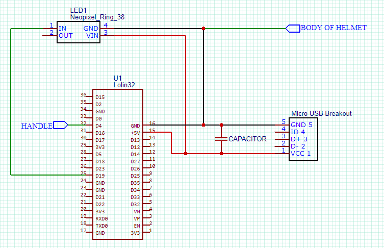
Wire up your board as shown and check that it works.
The net connected to the 'handle' will act as a touch button. On my board the ESP32 T0 is attached to D4. You will need to check this if using a different board.
Attaching a bare wire to this pin will behave the same. Pressing it twice will turn it on low like a night light. 3 times a little brighter and 4 times white.
Assemble the Parts Into the Helmet
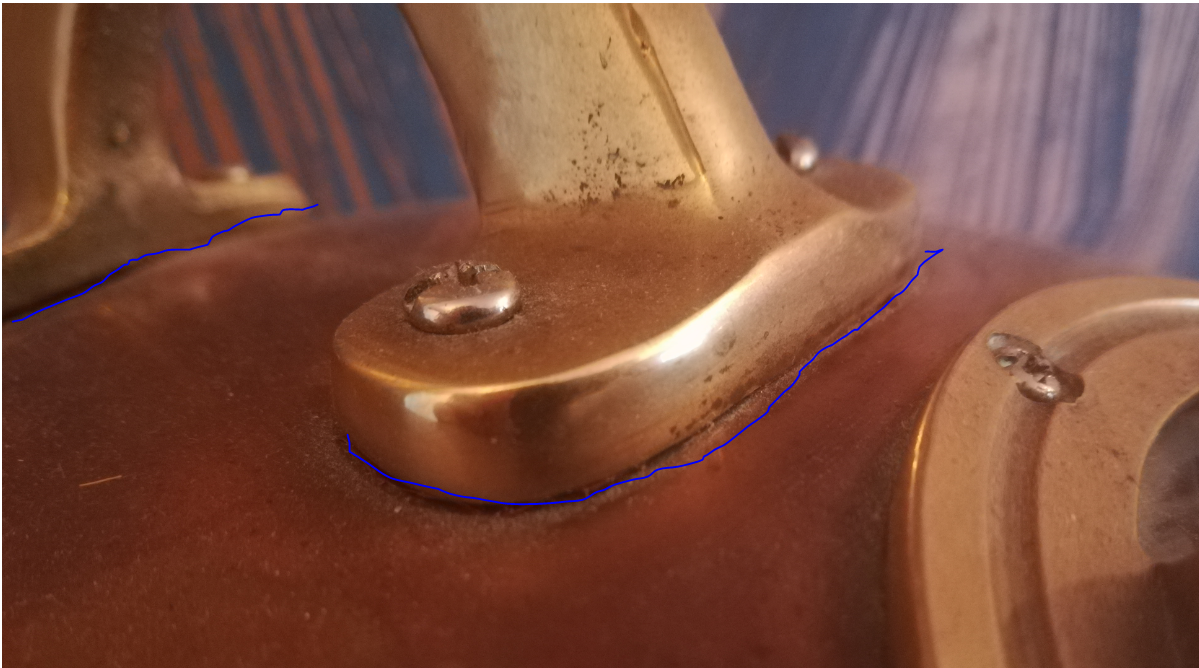
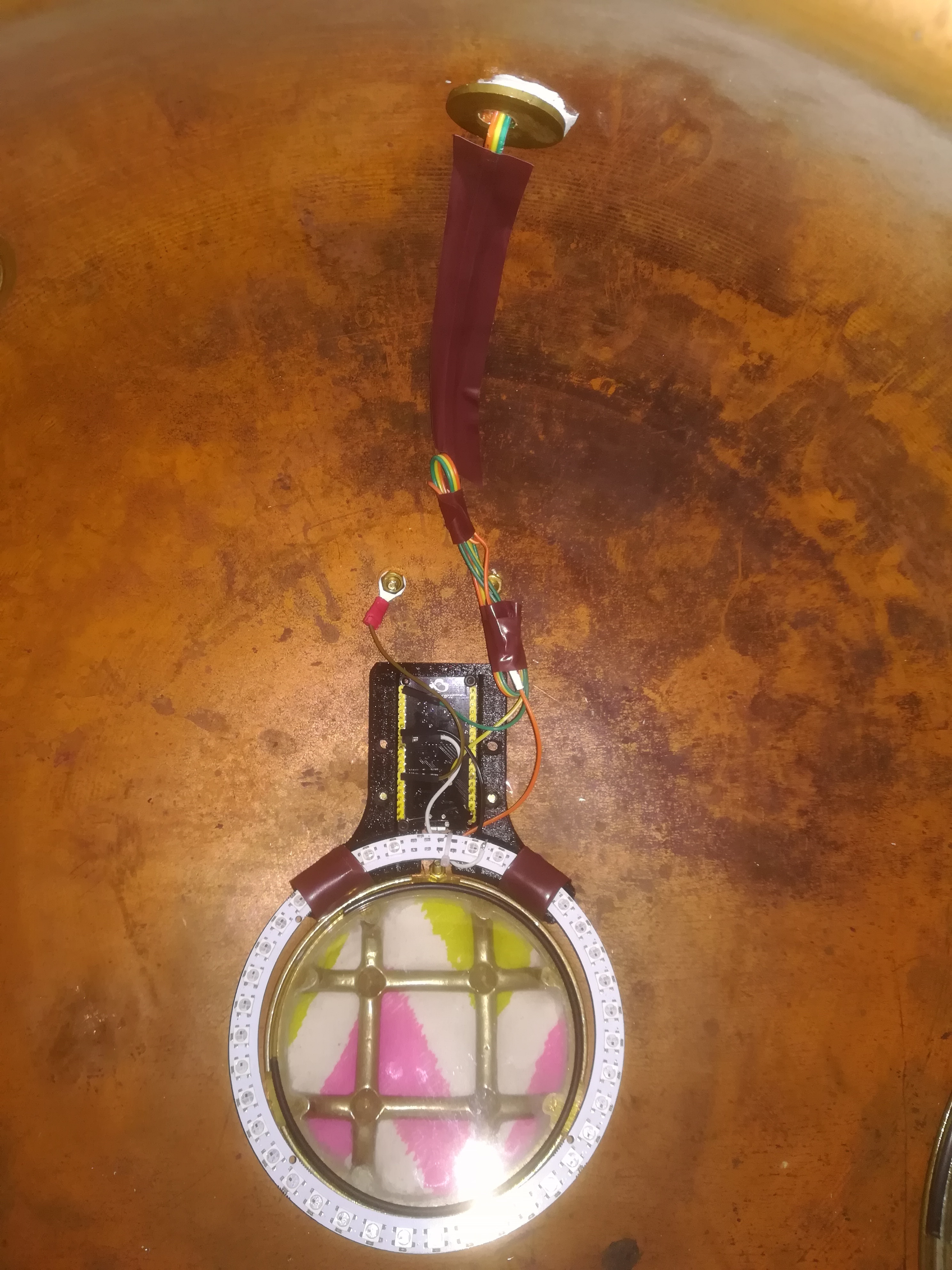
To turn on the lamp we will be using the handle of the helmet as a touch sensor. This means it must be insulated from the rest of the helmet. Remove the handle and cover the contact face with insulation tape. I used brown tape to make it blend in, it is highlighted blue in the image. Drill out the holes so that the screws are in clearance and reasseble with some plastic washers on the other side.
Connect your buttonpin to one ofd the handles screws using a crimp connector.
If you plan to use a floating power supply (pretty much all of them) then you will need to connect a GND pin to the body of the helmet in the same way. Now to turn on the lamp place one hand on the helmet and touch the handle with ther other.
Connect the Power
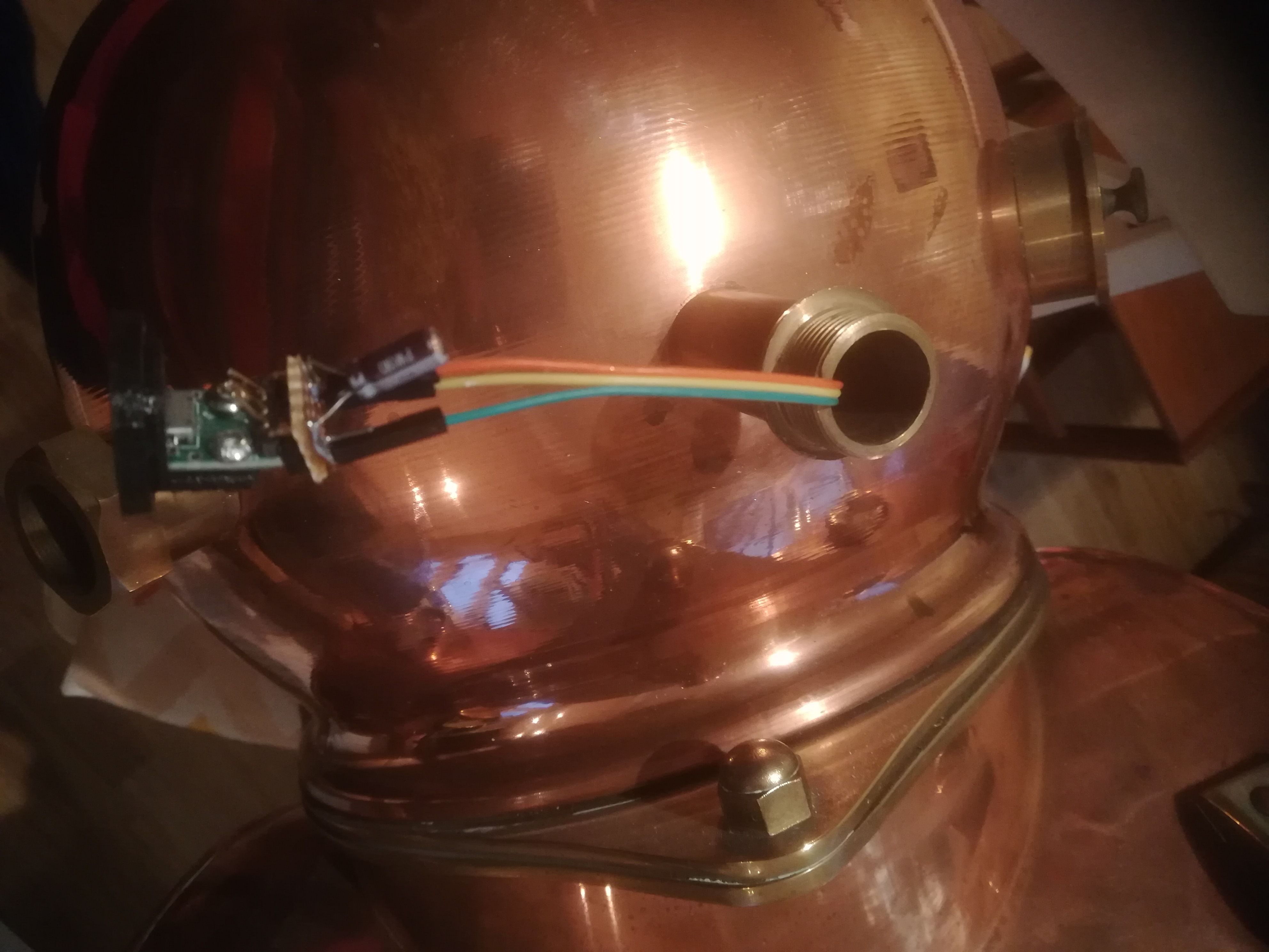
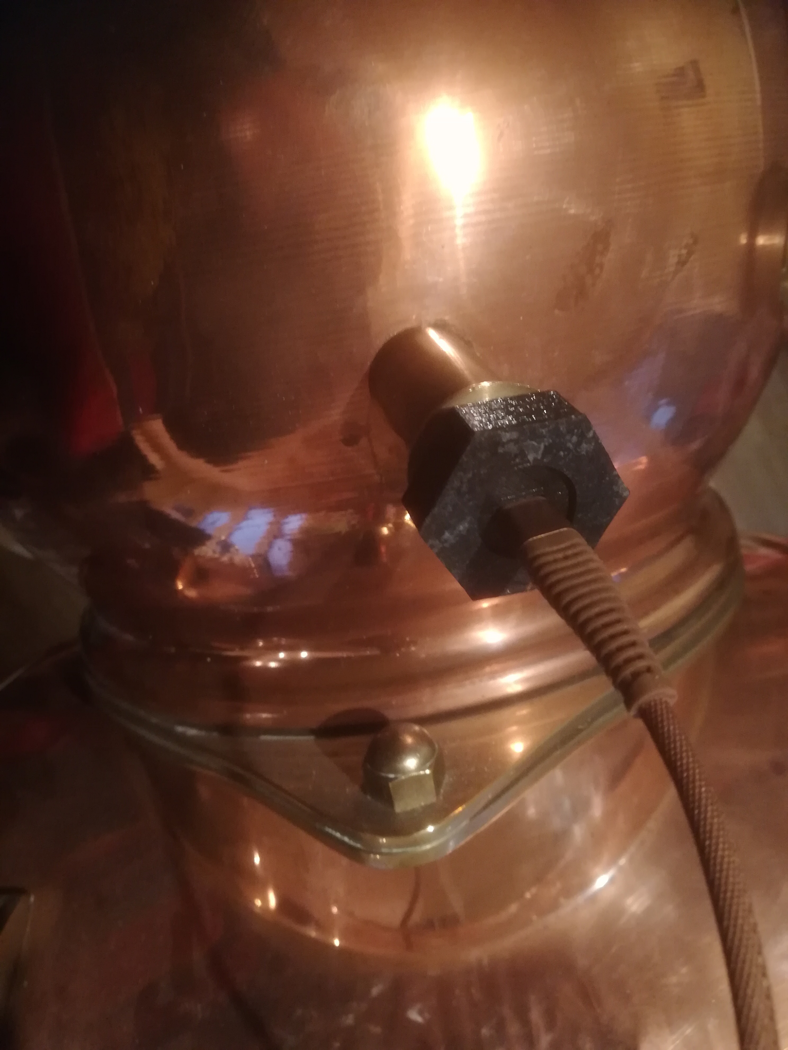

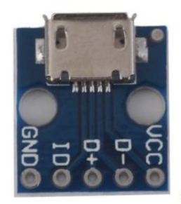
Screw the micro USB breakout board to the 3D printed bulkhead connector then secure in place with the nut.
Any 5V DC power supply can be used instead but usb chargers are plentiful in my house. I used a braided usb cable to mimmick an old flex and complete the look.
That is it you are done.
If you want to modify the code to try out extra colours, effects or timers then it will be available as an arduino OTA device for the first 10 minutes each time it is plugged in. This will then turn off to save power.