Distance Sensor With Built-in RGB Leds
by Don_Patrick in Circuits > Arduino
3512 Views, 11 Favorites, 0 Comments
Distance Sensor With Built-in RGB Leds
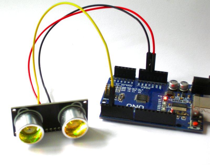
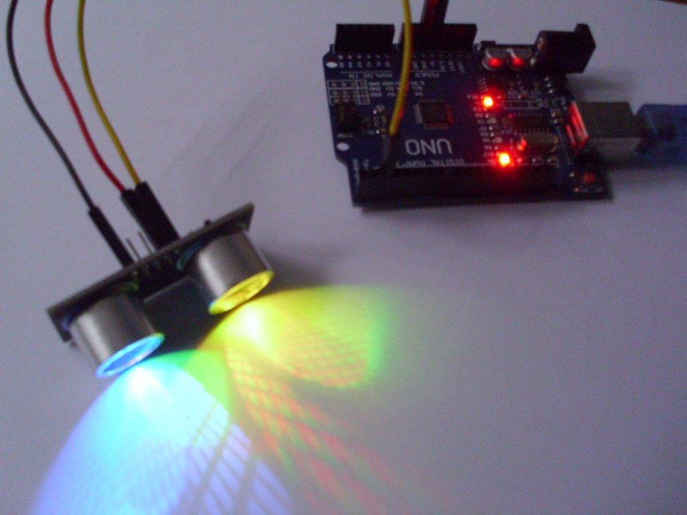
The RUS-04 is a new ultrasonic distance sensor that you can use in Arduino projects. The cool thing about it is that it has built-in RGB leds that you can use as a robot's eyes to display various states, or as a colourful indicator of the distance readings.
Although the distance measuring works the same as with a standard HC-SR04 ultrasonic distance sensor, for which there are already plentiful instructables, there was virtually no information available on how to make the RGB leds work!
After tracking down the manufacturer, translating the Chinese documentation, digging up the obscure code library it mentioned in a corner of Github, and debugging their code, I finally got the leds to work and decided to write the first instructable for it so that nobody else has to go through all of this.
Because how many programmers should it take to change an RGB light?
Supplies
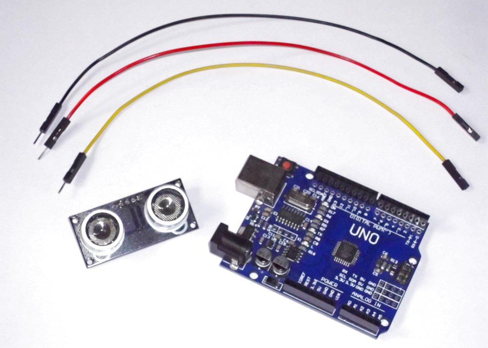
- Arduino Uno or similar
- The RUS-04 Ultrasonic Distance Sensor (sells around $10)
- 3 male-to-female jumper wires
Hardware Differences
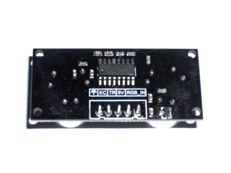
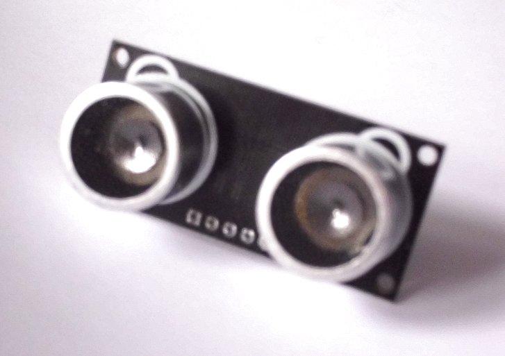
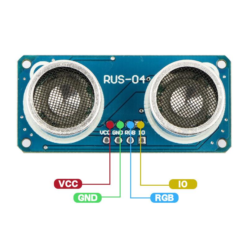
There exist two versions of the RUS-04 sensor module: The blue version is commonly depicted with four pins, but I received a black version with five pins. The only difference is that the blue version uses a single pin (IO) for both triggering and receiving the ultrasonic echo, while the black version uses the same pins as the standard HC-SR04 sensor module (ground, echo, trigger, 5V). Both versions have an additional RGB pin that is the focus of this instructable.
We won't cover distance measurement here, but should you have the blue version, remember to programmatically change the pin mode of the Arduino pin wired to "IO", from OUTPUT for triggering, to INPUT for reading the ultrasonic echo.
Should you have the black version, all pins for distance measurement work exactly as those on the standard HC-SR04 sensor module. If you want to use one fewer wire like the blue version, you can solder the trigger (TR) and echo (EC) pins together at the base or tip, and wire either one to the Arduino.
Wiring
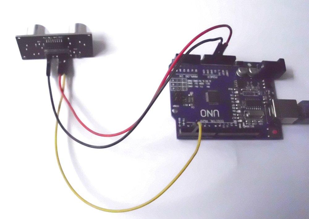
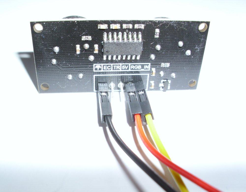
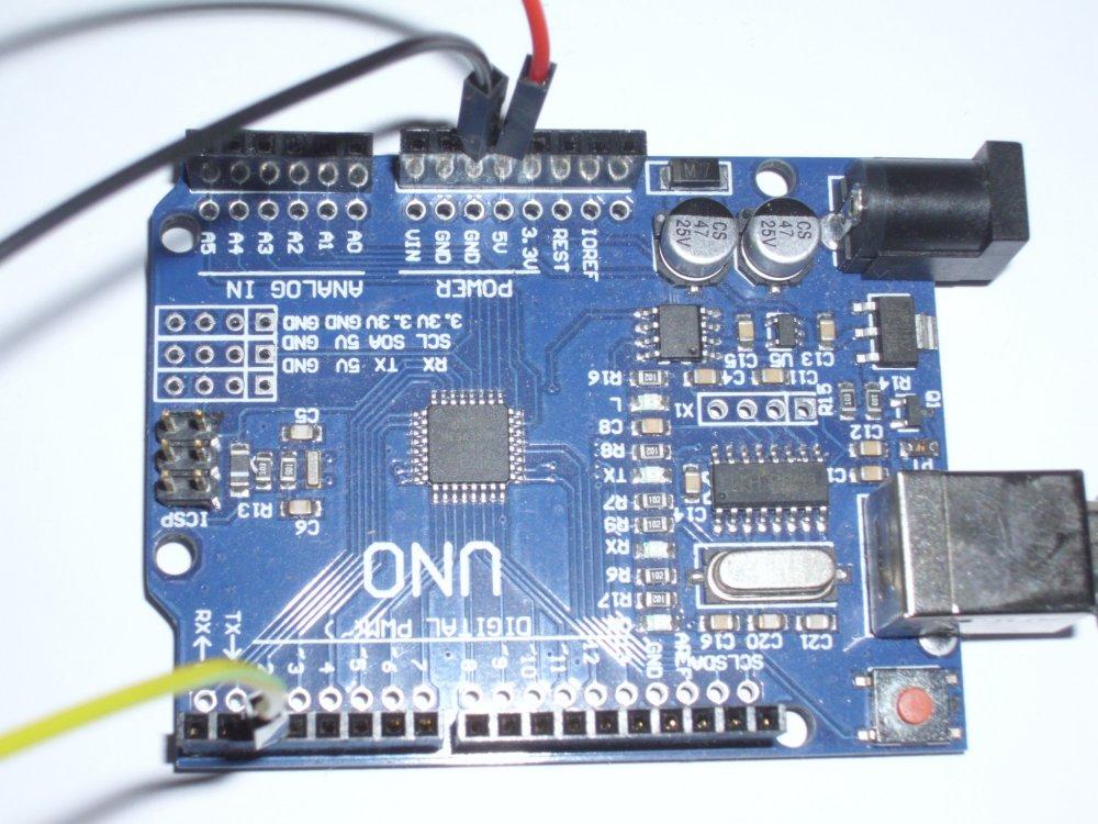
To control the RGB leds, we only need to connect three wires.
For the blue version:
- GND (black) connected to GND
- 5V (red) connected to VCC
- Pin 2 (yellow) connected to RGB
For the black version:
- GND (black) connected to the ground symbol
- 5V (red) connected to 5V
- Pin 2 (yellow) connected to RGB_IN
You can use any digital output pin of the Arduino that you want, but we'll go with pin 2. The module will also work on 3.3V input instead of 5V. It draws 65mA current when all leds are on, 3mA when all leds are off.
For distance measurement you would also wire the echo and trigger pins, but again, those are already well covered in other tutorials.
Install the RGBLed Code Library
To control the RGB leds, you need to use the RGBLed code library, which consists of two files: RGBLed.cpp and RGBLed.h . The original code switched red and green colours around in several functions, so you would better download the corrected files here. To install them, you can zip them up, then in the Arduino IDE program navigate to Sketch > Include Library > Add .ZIP Library, and select your .zip file.
Alternatively, you can just place the two files in the same folder as your Arduino sketch. It doesn't get easier than that.
Code
Below is a basic Arduino sketch for changing the RGB led colours.
There are 6 RGB leds in the module. Led numbers 1,2,3 are located in the left cylinder, 4,5,6 in the right cylinder.
Basically you pass the led number to .setColor(), followed by values ranging from 0 to 255 for the red, green, and blue colour channels, and then use .show() to actually make the lights change to those colours. You can use an online colour picker to get the RGB values easily.
The 6 leds can be set individually, and the sensor module will remember the last-set colours even if you reset the Arduino. To set all leds to the same colour, pass 0 as the led number, e.g. .setColor(0, 255,255,255) sets all leds to white.
#include "RGBLed.h"

// Set the pin nr wired to the ultrasonic sensor's pin marked "RGB" or "RGB_IN":
const int RGBpin = 2;

// The ultrasonic sensor has 6 built-in leds in total: 3 in each cylinder.
RGBLed ultrasonicRGB(RGBpin, 6);

void setup() {
// Set the 3 leds in the first cylinder to one colour,
// passing values from 0 to 255 for red, green, and blue.
for(int ledNr = 1; ledNr <= 3; ledNr++) {
 ultrasonicRGB.setColor(ledNr, 200, 255, 0);  //yellow
}

// Set the leds in the other cylinder individually:
ultrasonicRGB.setColor(4, 255, 0, 0);  //red
ultrasonicRGB.setColor(5, 0, 255, 0);  //green

// Alternatively you can pass a hex colour value:
ultrasonicRGB.setColor(6, 0x0000FF);  //blue

// Apply the changes:
ultrasonicRGB.show();
}

void loop() {
}
To achieve a fancy spinning rainbow effect, you can replace the empty loop() function with the following code, passing hexadecimal colour values to .setColor() instead of separate RGB values, for the sake of ease.
// Set up some hex colours:
const long RED    = 0xFF0000;
const long ORANGE = 0xFF8800;
const long YELLOW = 0xFFFF00;
const long GREEN  = 0x00FF00;
const long BLUE   = 0x0000FF;
const long PURPLE = 0xFF00FF;

// Put the colours in an array:
const long RAINBOW[6] = {RED, ORANGE, YELLOW, GREEN, BLUE, PURPLE};
int index = 0;

void loop() {
// Shift the rainbow array's index across [0] to [5], red to purple:
index += 1;
if(index > 5) {index = 0;}

// Set the colours for all leds, shifting at each loop:
for(int ledNr = 1; ledNr <= 6; ledNr++) {
 int colourNr = (index + ledNr % 2) % 6;
 ultrasonicRGB.setColor(ledNr, RAINBOW[colourNr]);
}
ultrasonicRGB.show();

// Change the colours with a certain interval.
// The smaller the delay, the faster the animation.
delay(150);
}
Both examples are combined in the test.ino file, which you can upload to your Arduino from the Arduino IDE.
Downloads
Result
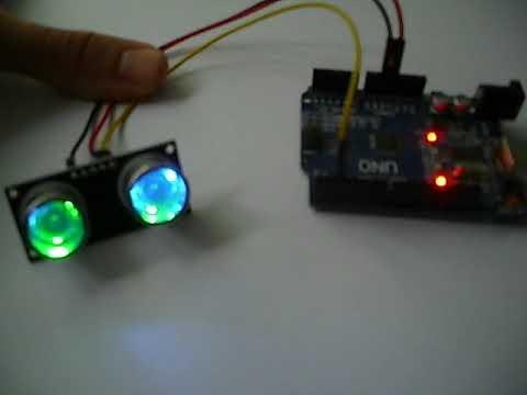
There you go, every colour combination you could want, just one cylinder short of a full traffic light. I am glad I didn't have to ship the sensor module back because I couldn't figure out how it worked at first, and now with this instructable, you'll have nothing to worry about. It is a most welcome replacement for my old distance sensor, and I hope you'll have fun with it too.
Edit the code and experiment to your heart's content!
The code and library from this instructable are also available on Github