Digital Wall Calendar and Home Information Center
by dstryker in Circuits > Raspberry Pi
363875 Views, 2390 Favorites, 0 Comments
Digital Wall Calendar and Home Information Center
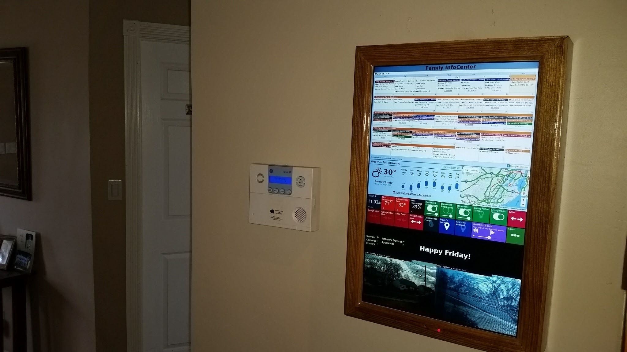
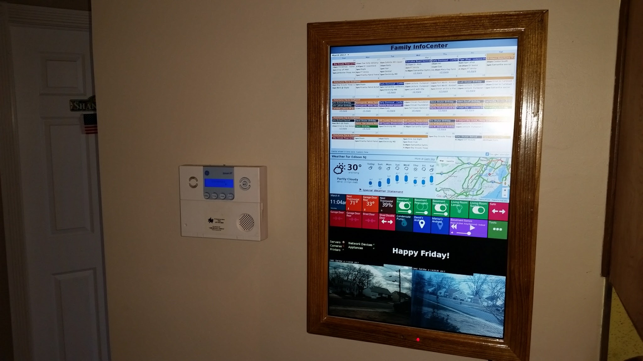
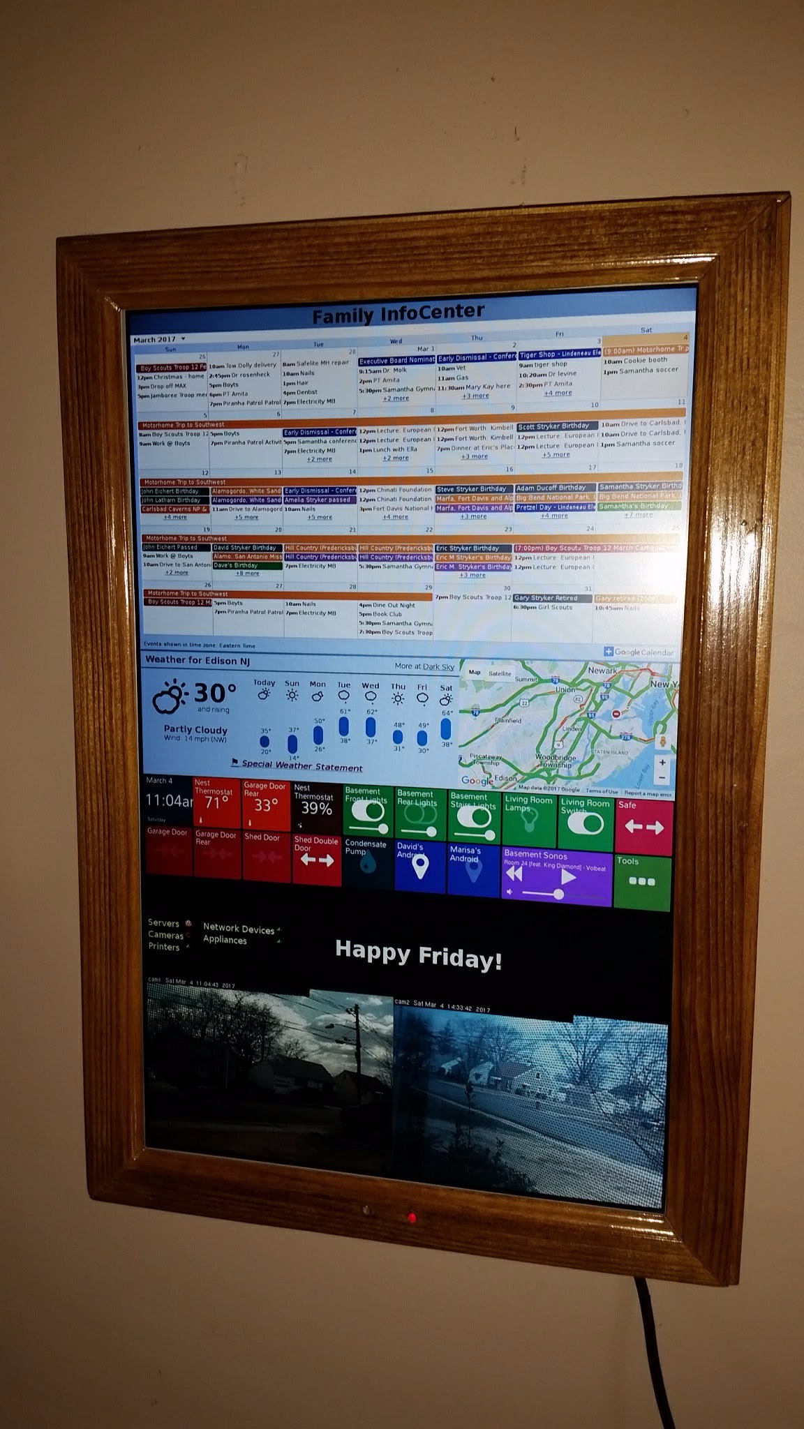
In this Instructable I'll be turning on old flat screen TV in to a wood framed digital Wall Mounted Calendar and Home Information Center powered by a Raspberry Pi.
The goal was to have at a glance access to pertinent information for all members of the family, replace the static paper wall calendar and provide even more useful real-time information then a paper calendar ever could. The features it includes are:
- A monthly calendar synced with 6 family members as well as the calendars for the kid's sport teams, schools and other organizations to which we belong (11 total). (Google Calendar)
- Local weather forecast. (forecast.io)
- Local traffic map. (Google Maps)
- Display conditions inside the house, such as temperature, humidity, garage door status open/close, light status on/off, basement leak sensor status and more. (Smart Things and Smart Tiles)
- Monitor the status of devices on our home network such as servers, IP cameras, IP printers, routers, WiFi Access Points and other Network Devices.(Xymon)
- View the outdoor IP cameras. (Axis)
- Infrared control of the LCD by the Raspberry Pi to turn on and off as per a schedule.
- Date & time.
- Even a small "digital chalk board" for anyone in the family to leave notes. (Google Doc)
Materials
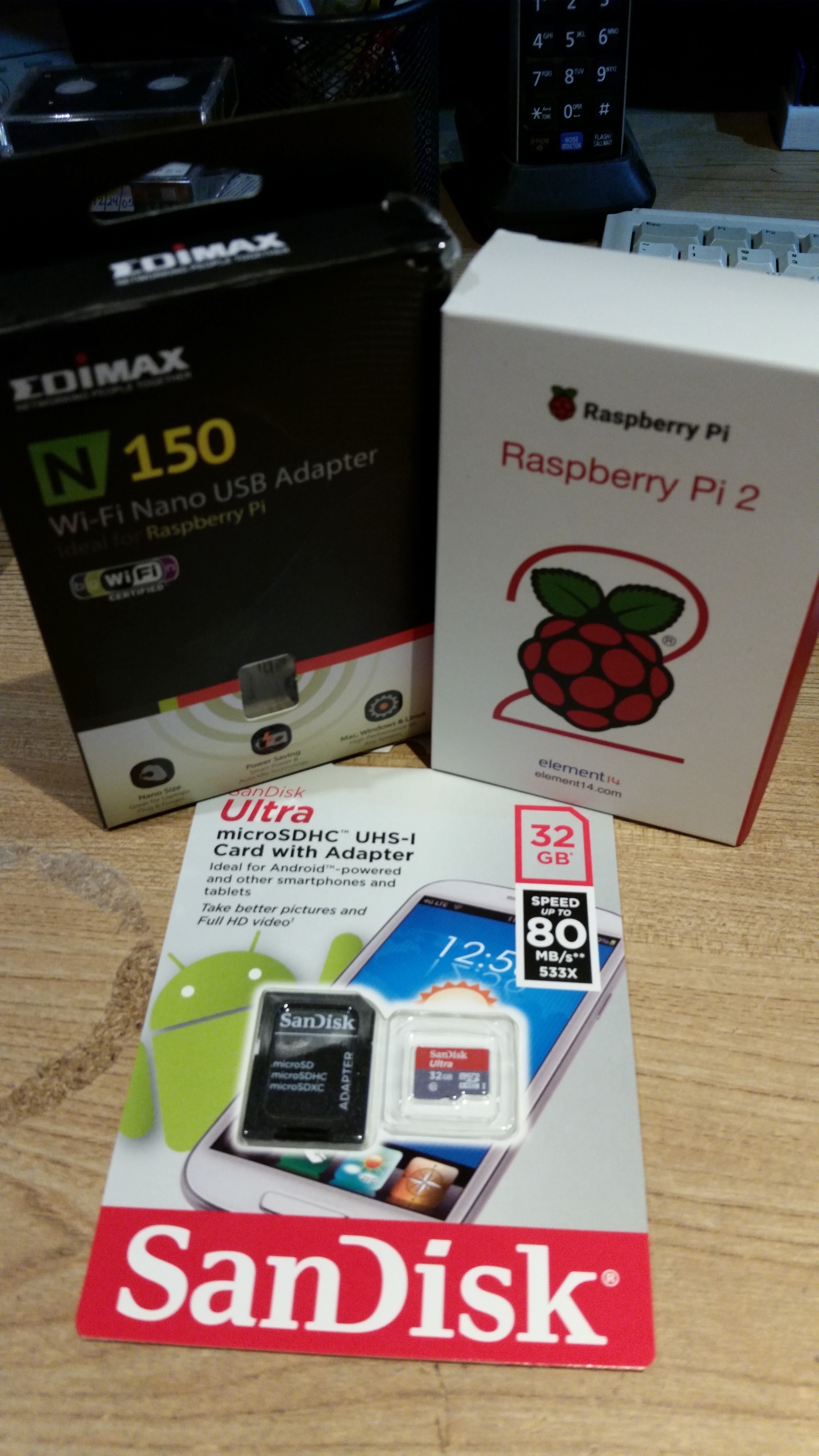
Electronics
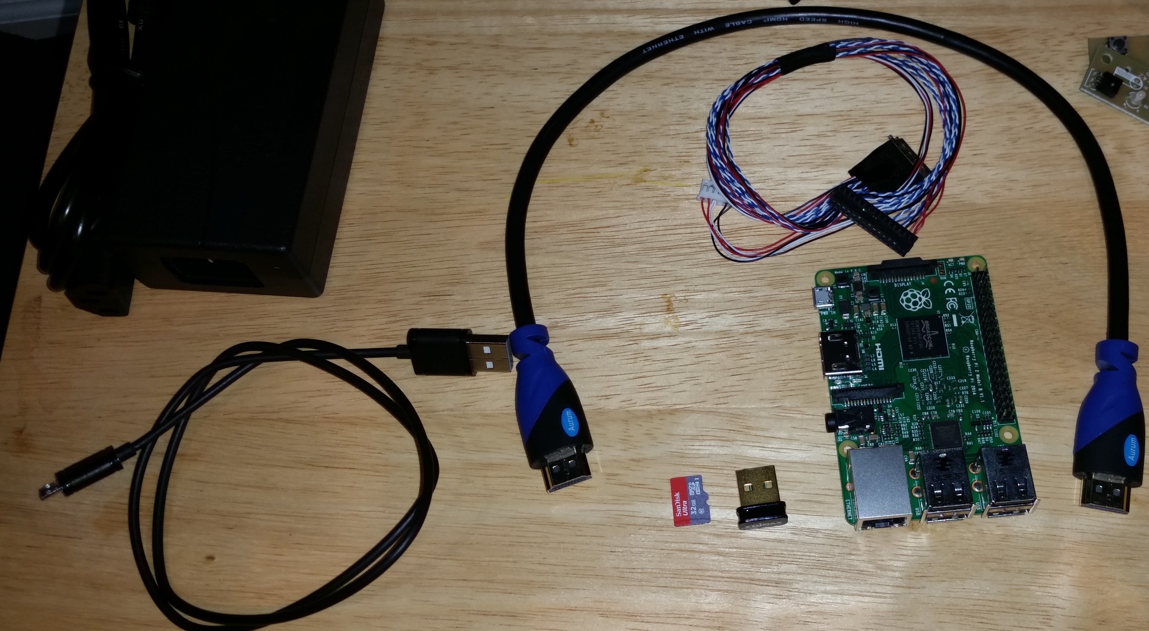
- Raspberry Pi 2
- Edimax USB Wifi adapter
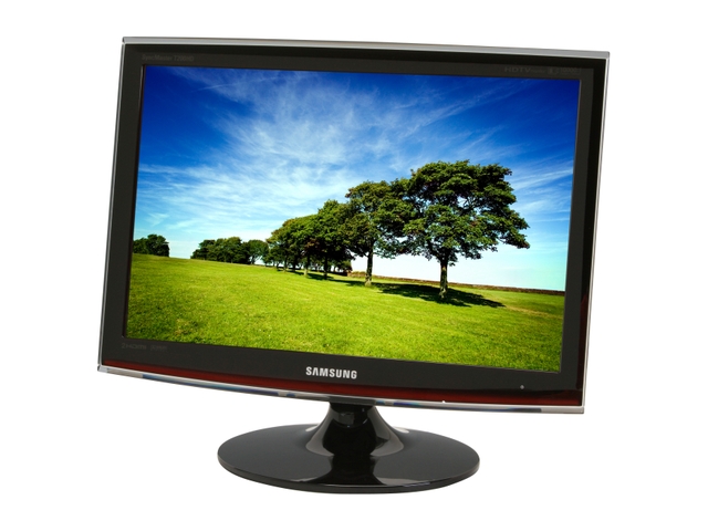
- Old flat screen TV, I used a 22" Samsung T220HD
- 18" HDMI cable
- Right angle HDMI adapter
- Micro SD card at least 4Gb
- Sacrificial micro USB cable and power cord
- Wireless keyboard/mouse (optional)
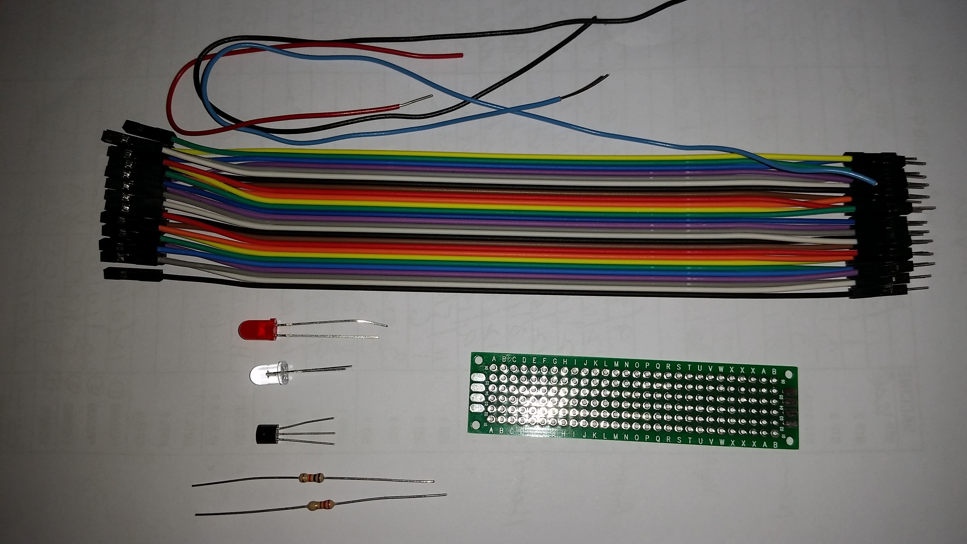
- 5mm LED
- 1 2N2222 transistor
- 2 resistors (220ohm and 10k Ohm)
- 940nm IR LED
- small prototyping PCB
- Male to female jumper wires
- 22 gauge solid jumper wire and 20 gauge stranded wire
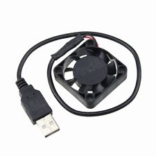
- 40mm 5v PC fan with USB A plug
Hardware
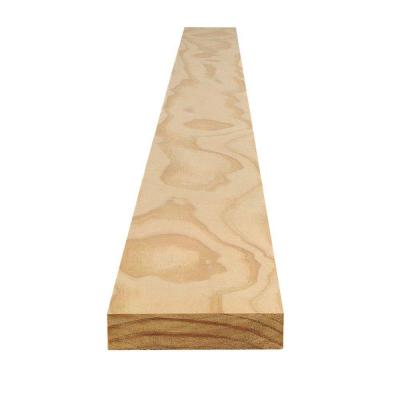
- 5/4" x 3-1/2" x 6' finish grade pine
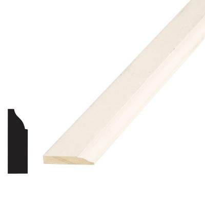
- 3/8" x 1-1/4" x 6' pine stop moulding
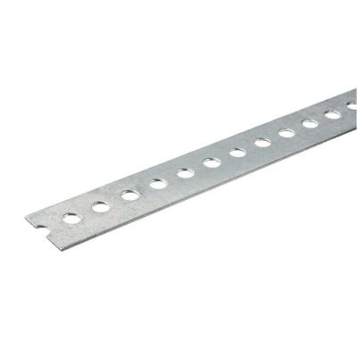
- 1-3/8" x 36" Steel flat bar
- Wood stain and polyurethane or paint
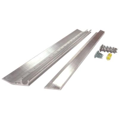
- Metal french cleat
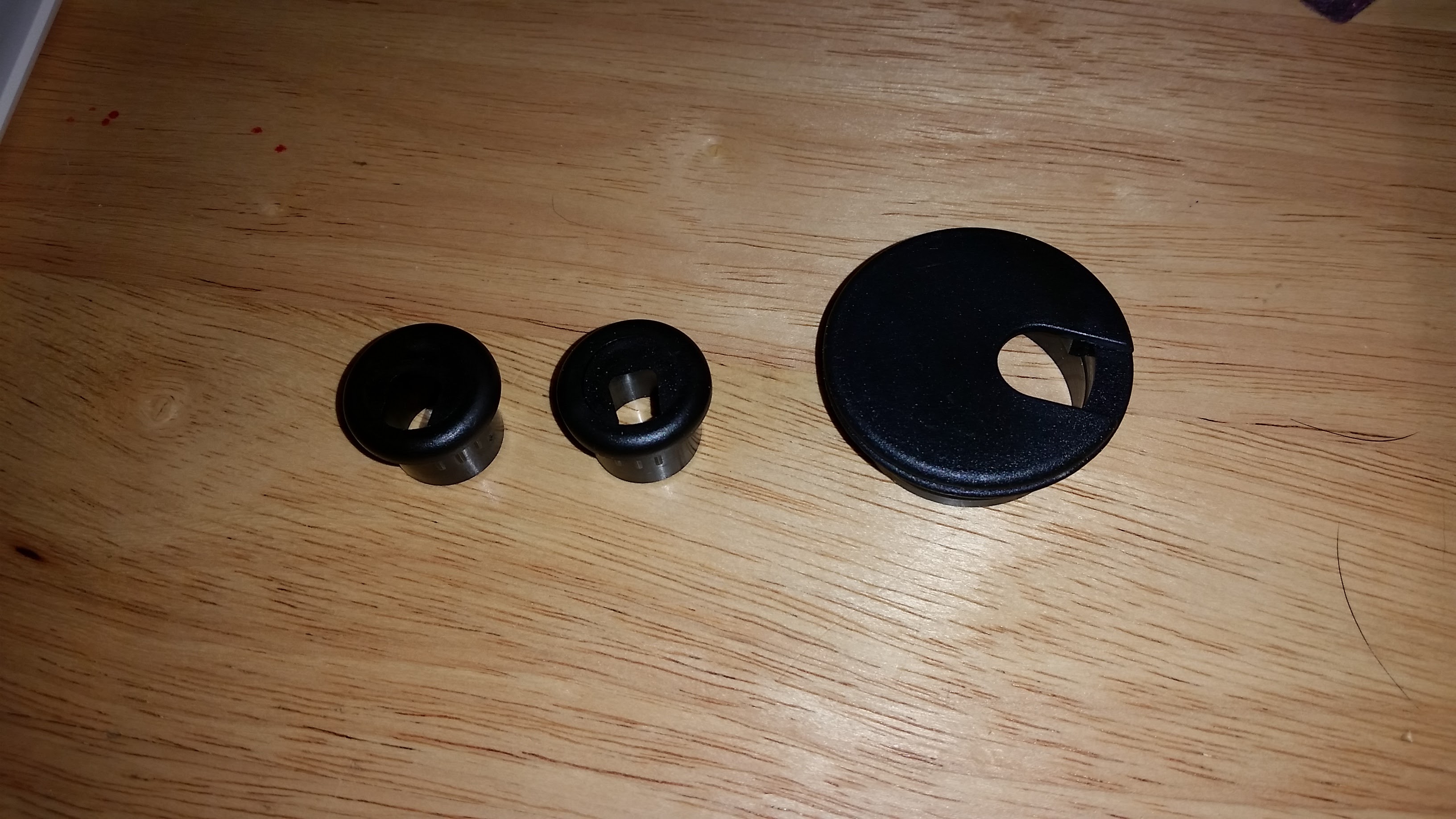
- Two 3/4" & one 1-1/2" plastic grommets
- Mounting screws & standoffs to mount raspberry Pi
- Wood glue & wood putty
- Heat shrink tubing or electrical tape
-
A few wood screws, paint brushes and sandpaper
Tools
- Miter saw
- MIG welder
- Soldering iron & solder
- Biscuit joiner & #10 biscuits
- Pneumatic finish nailer
- Router
- Drill
- 3/4" & 1-1/2" Hole Saw
- Random orbit sander
- Hot glue gun
- Multi-meter
- Asst. hand tools
Disassemble
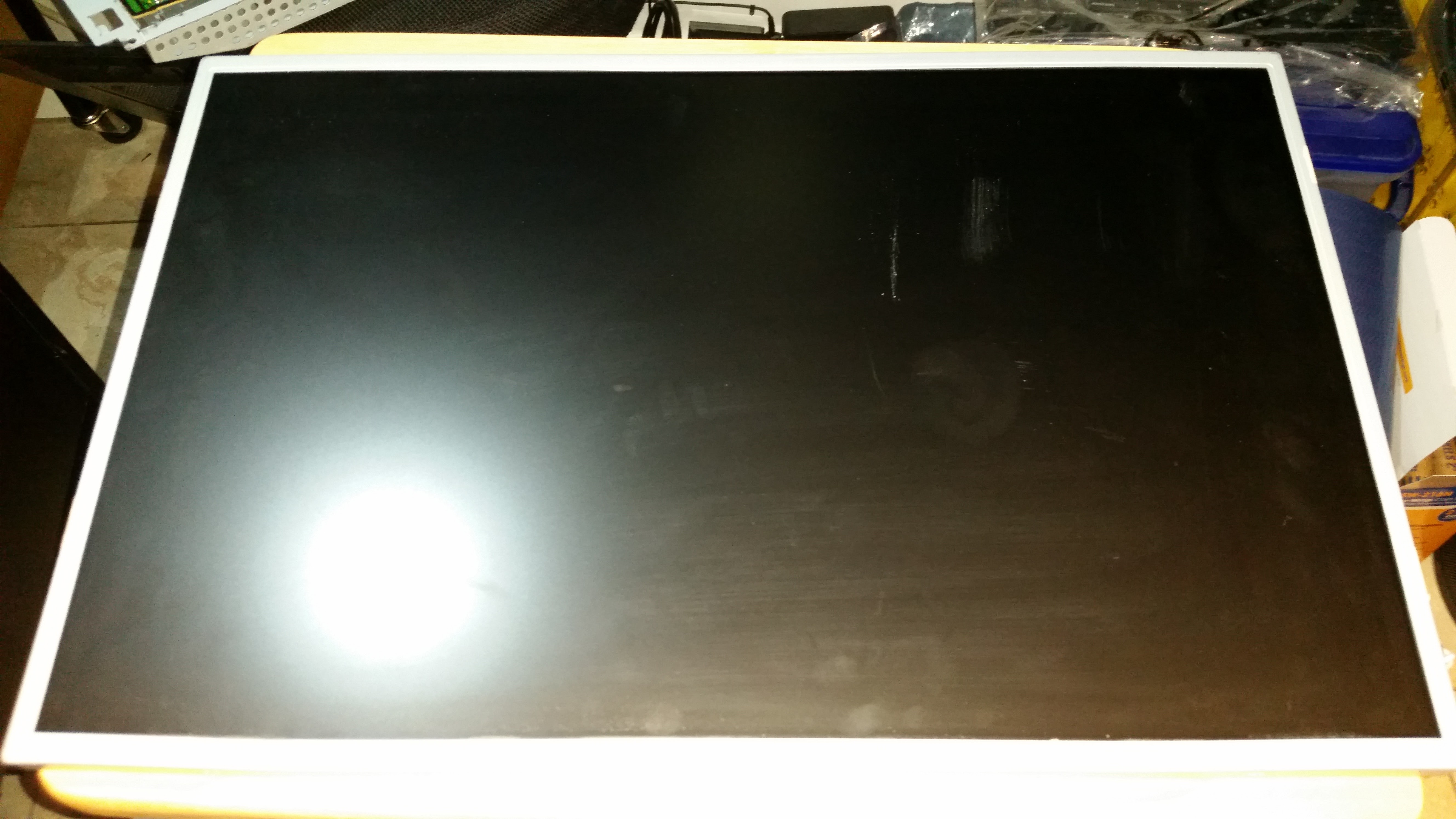
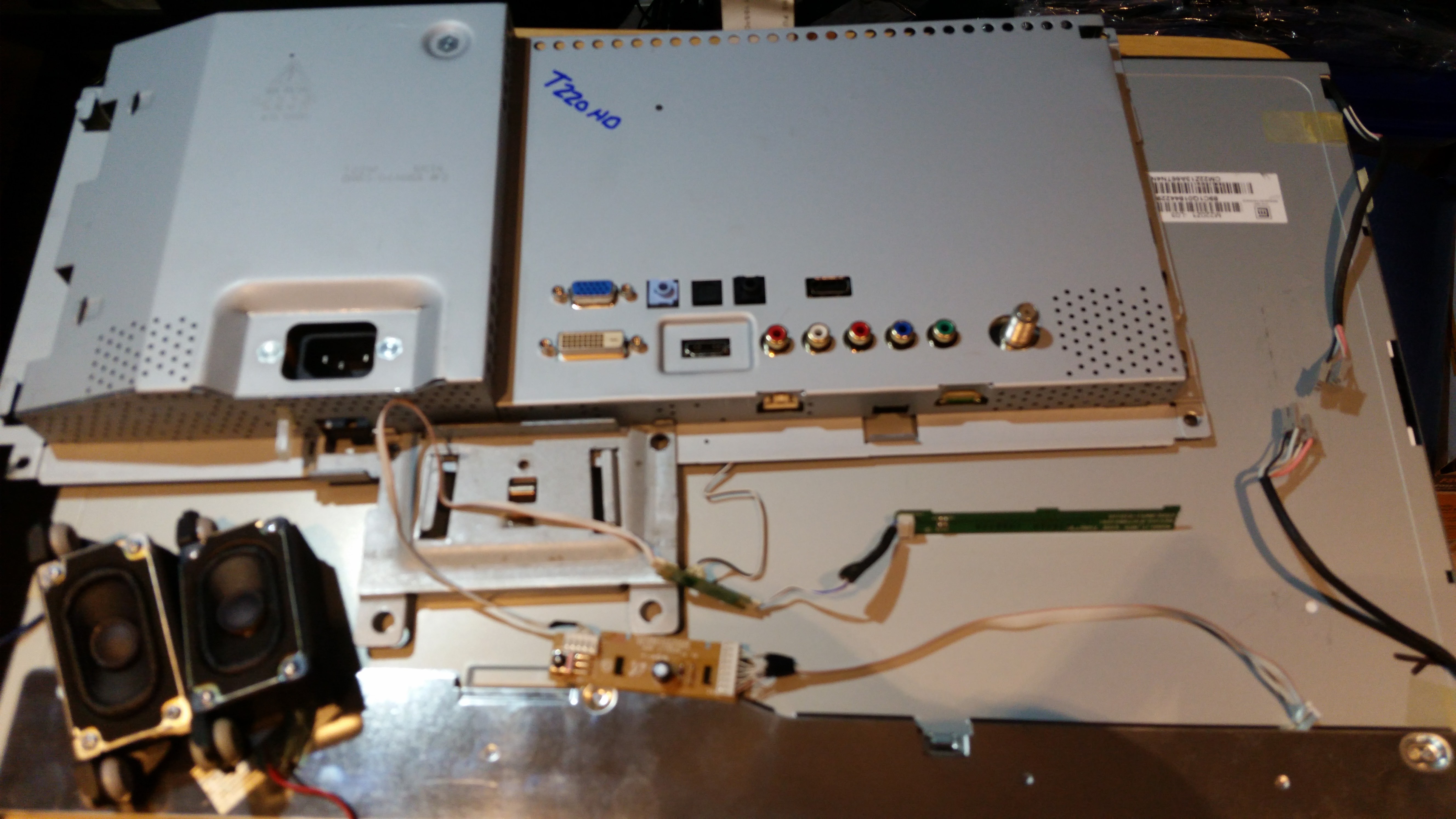
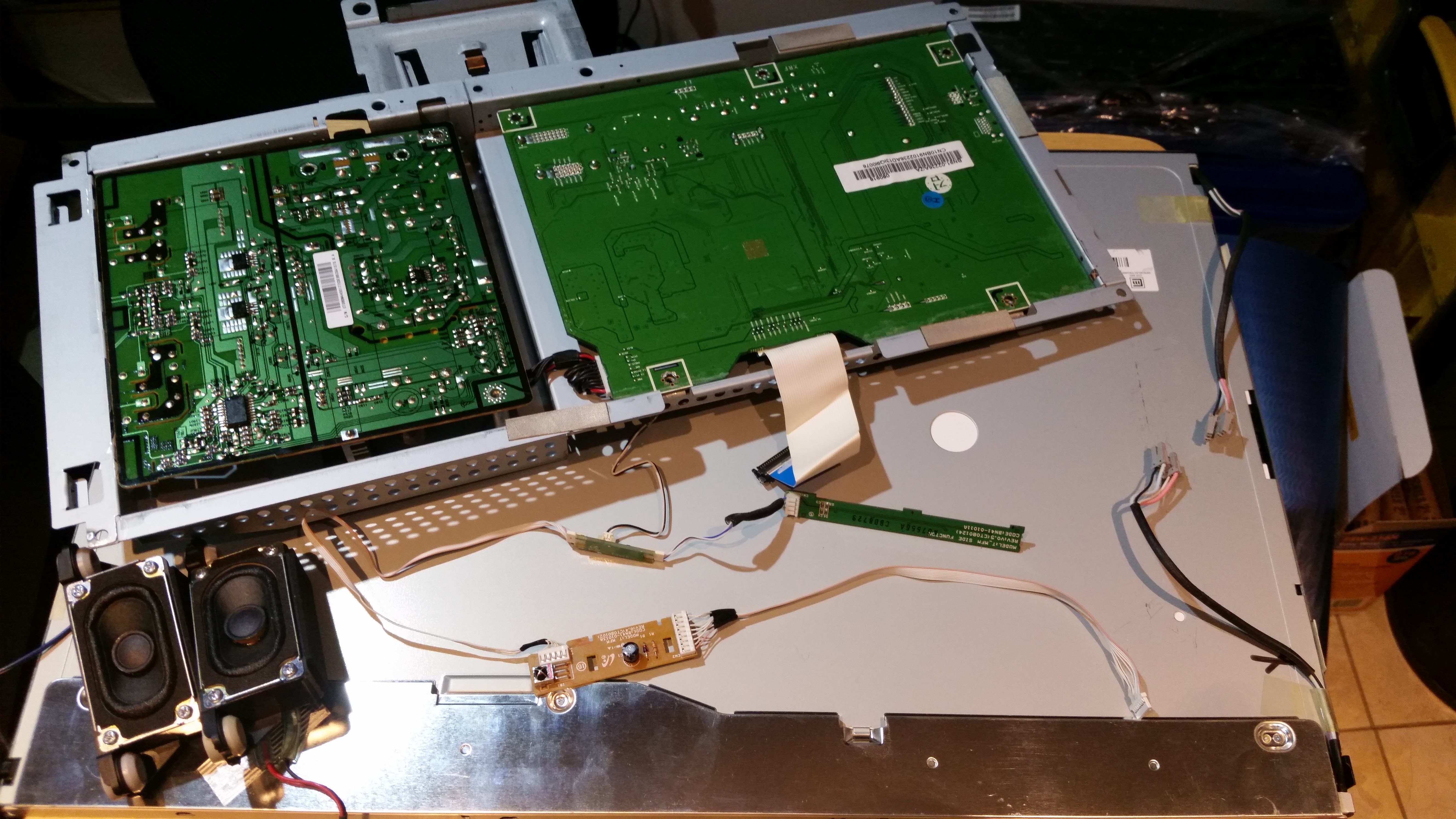
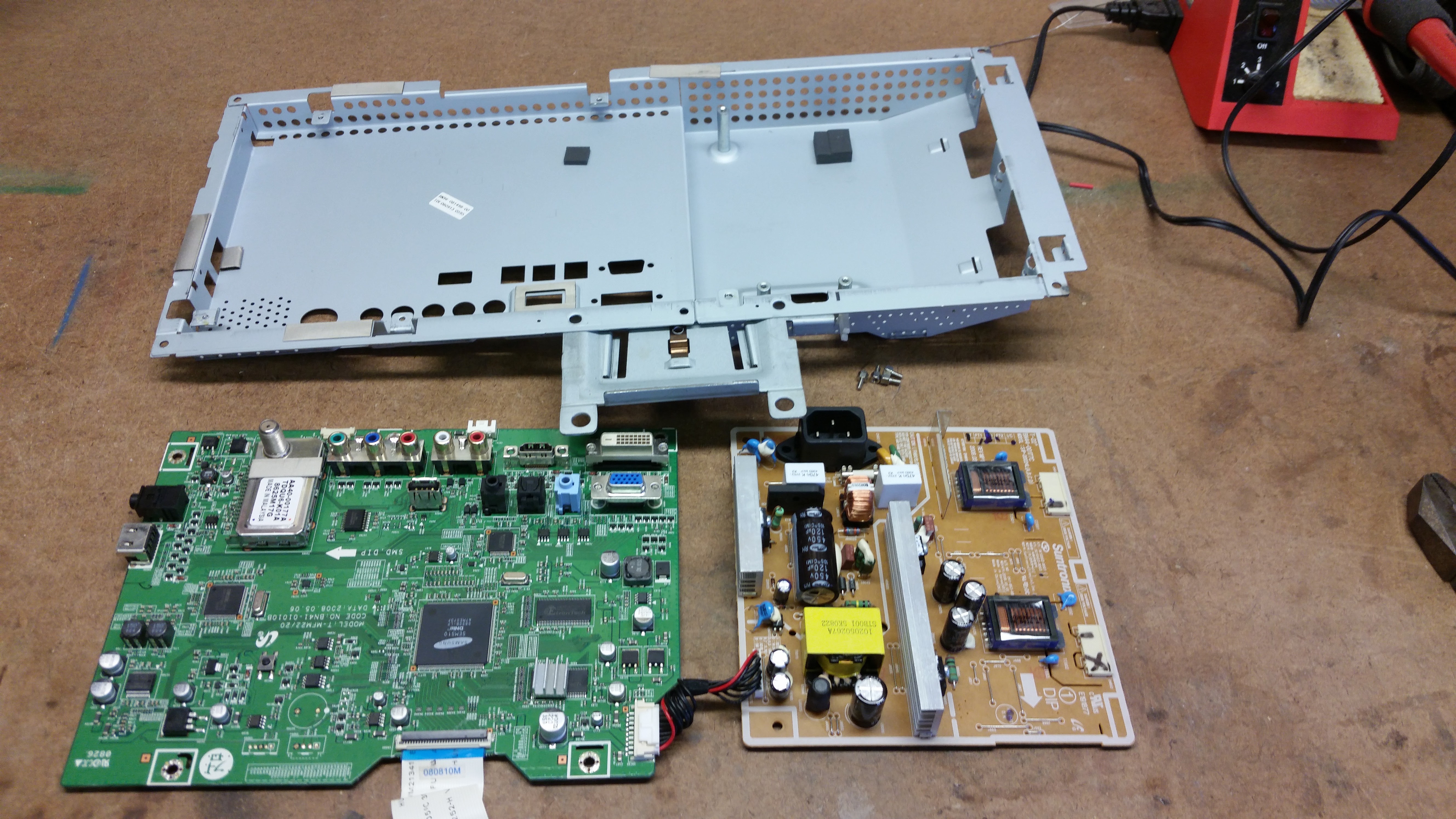
Disassemble - Begin by disassembling the 22" Samsung HD T220HD TV. The disassembly is fairly easy and is thoroughly documented in the service manual below (pg. 8-12) so I won't duplicate those instructions here. Be careful not to damage the LCD in the process and save all of the internals. The plastic housing and stand can be discarded.
Downloads
Modify Factory Electronics Tray
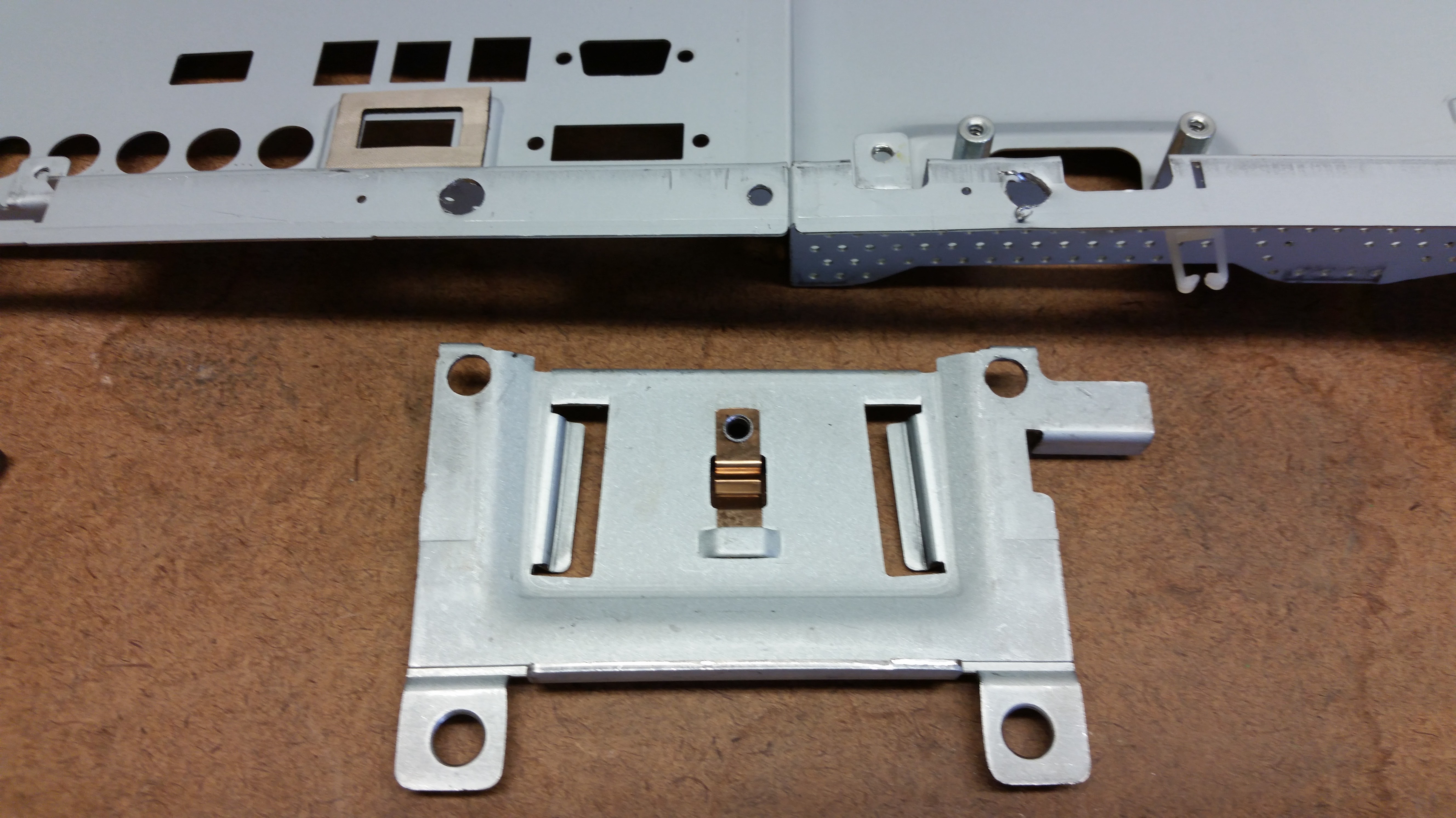
- Remove Bracket - With the power supply and PCB removed from the metal tray, start by drilling out the two press connections holding the metal bracket to the tray and remove the bracket.
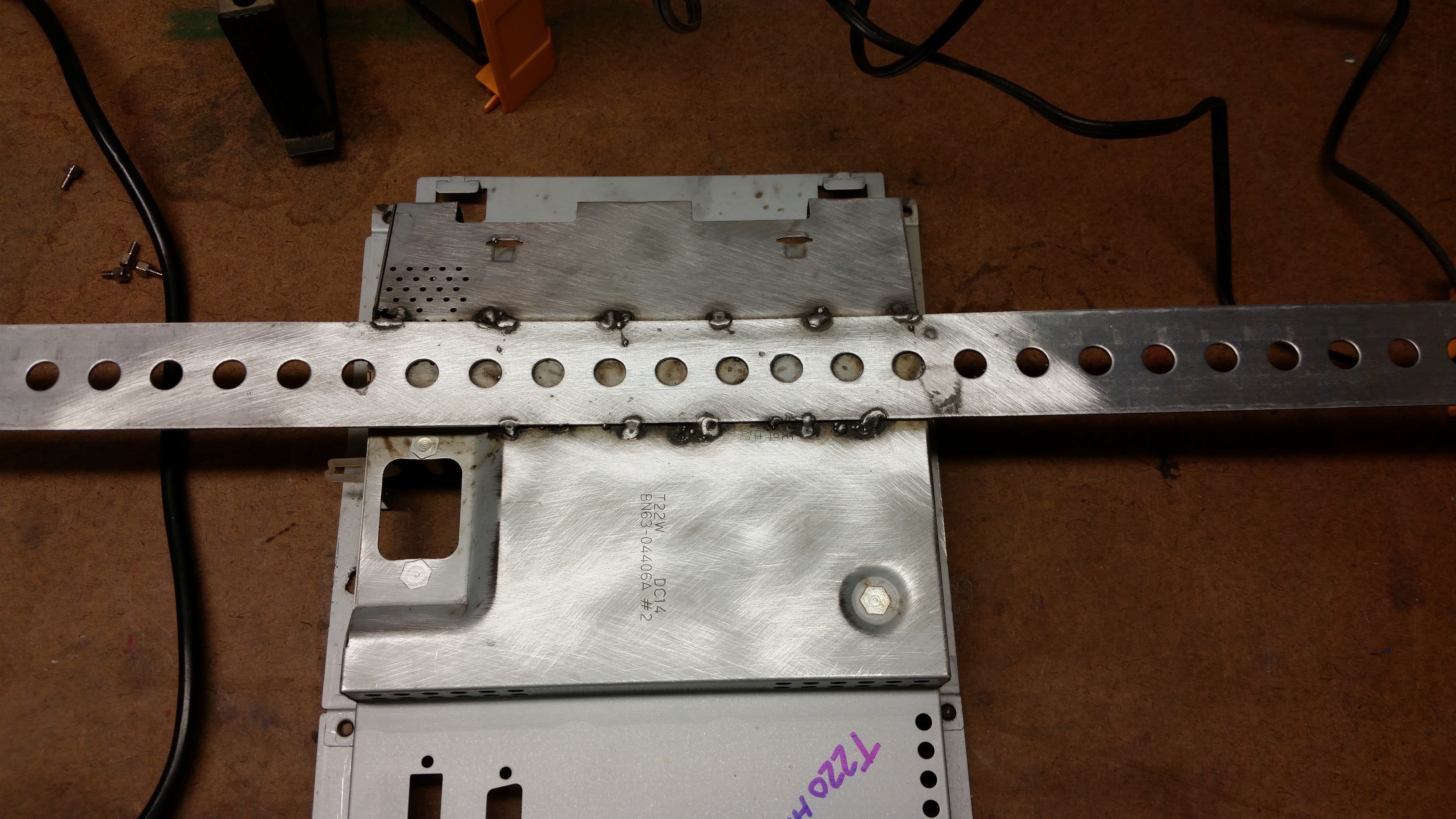
- Add Tray Support - Once the bracket is out of the way, center the steel flat bar perpendicular to the tray just above the power inlet plug. Using a MIG welder, tack it in place. This will be used to support the tray inside the frame later. If you don't have access to a MIG welder you could drill holes and mechanically fasten with nuts and bolts but be sure you have enough clearance between the heads of the bolts and the power supply once it is reinstalled to avoid short circuits. The flat bar is intentionally left long for the time being and will be trimmed to fit inside the frame later.
Relocate Power Inlet
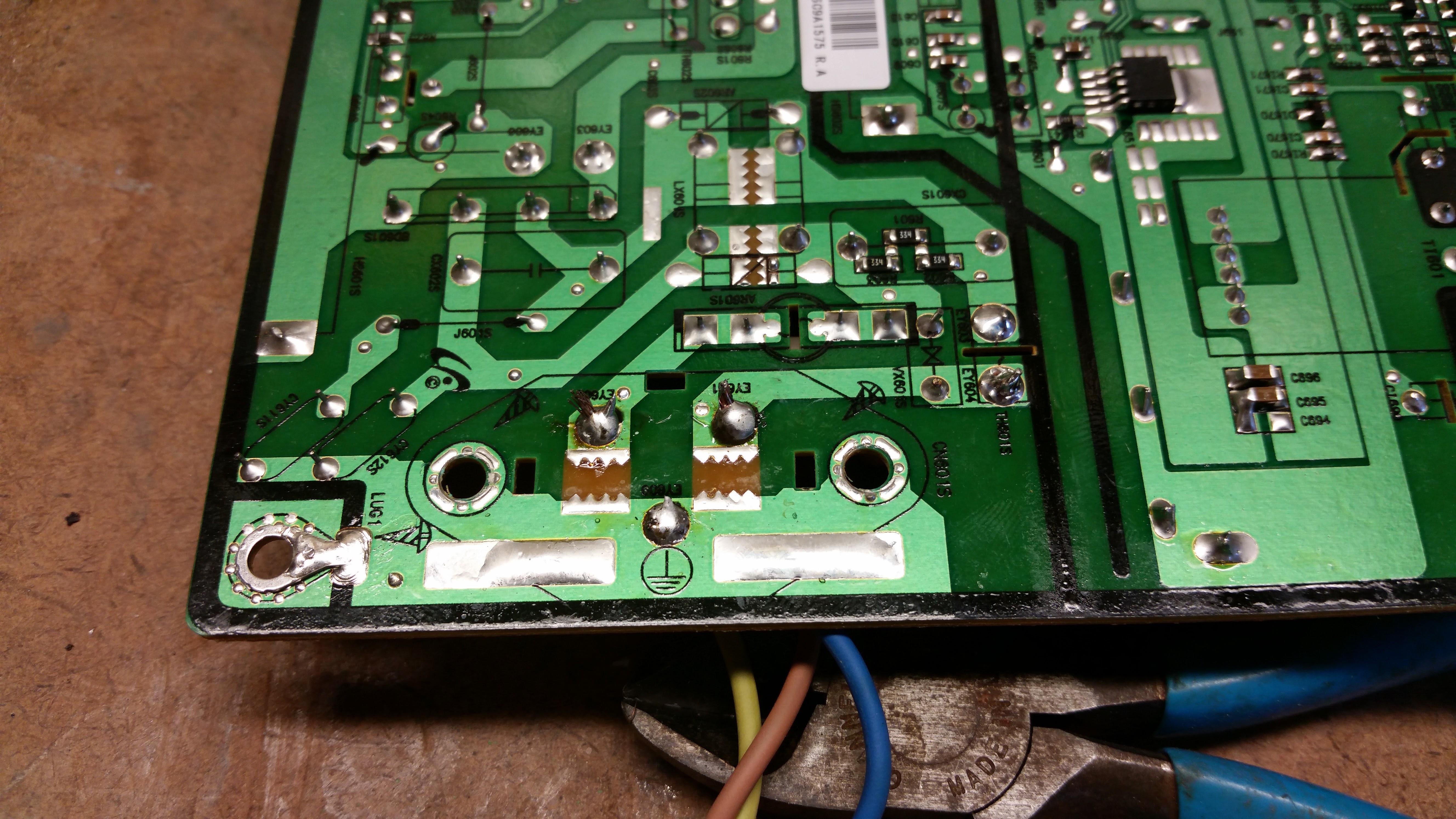
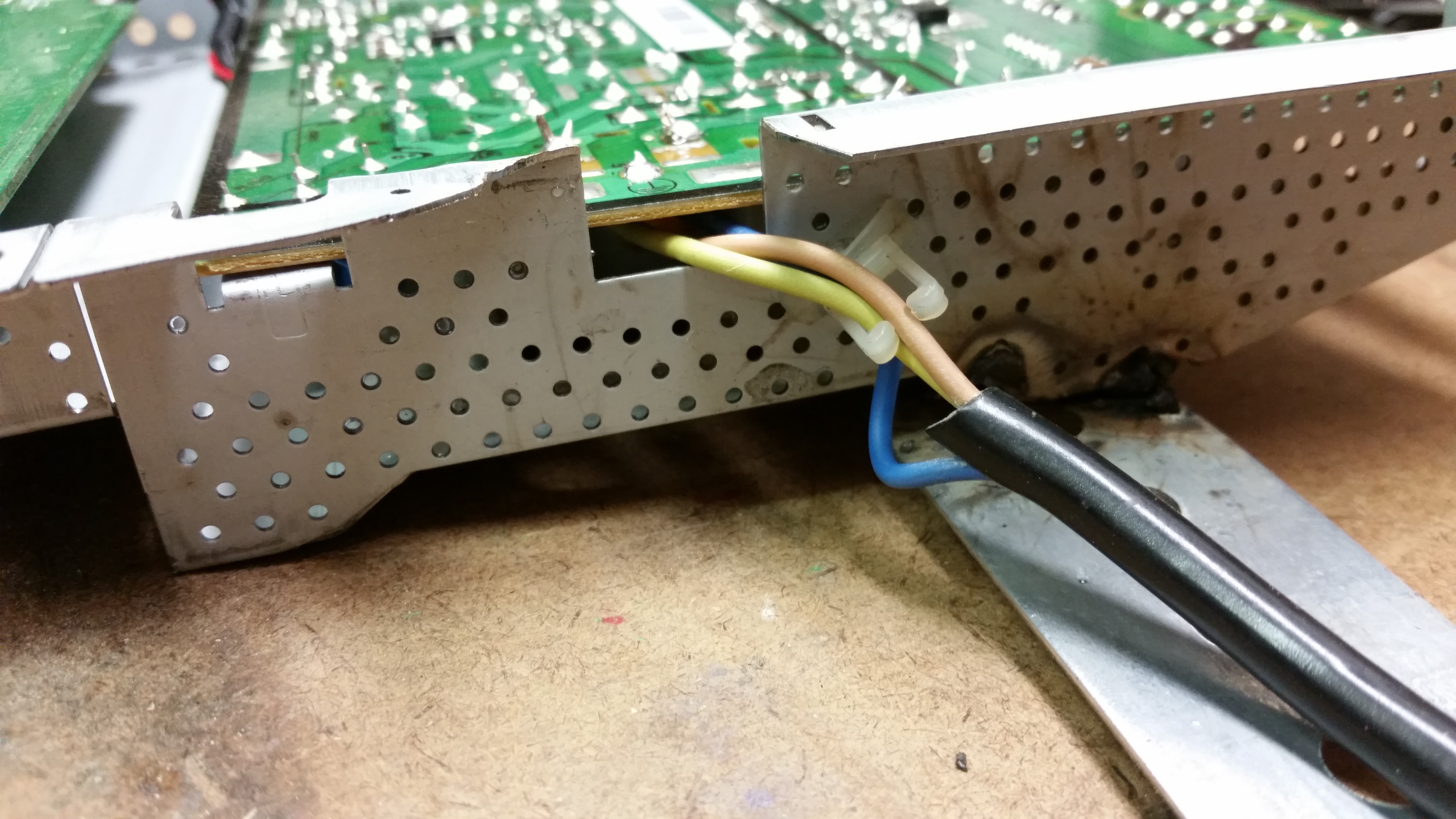
Steps 4-8 deal with the new and hacked factory electronics
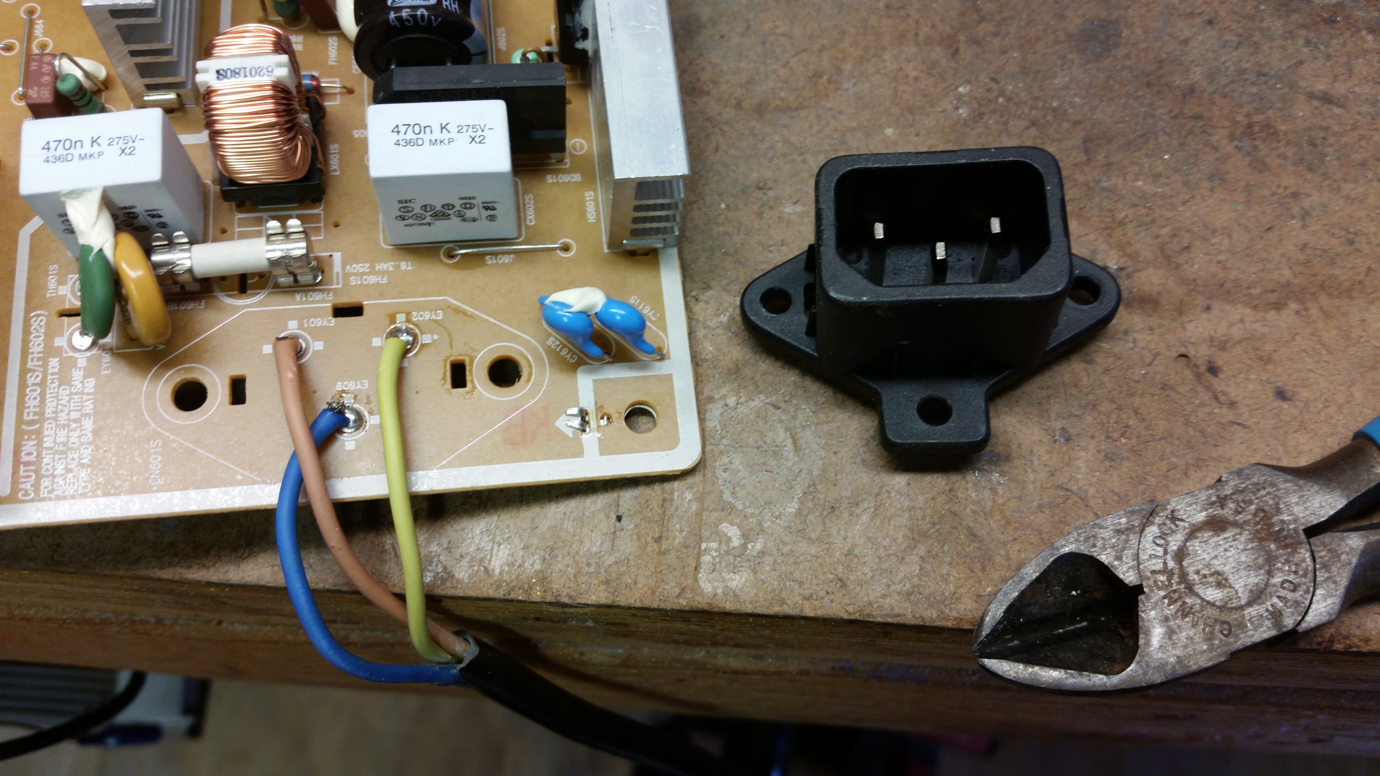
- Relocate Power Inlet - (Optional - Originally I didn't expect to have the depth needed to fit the power cord without it protruding out the rear of the frame and therefore causing it to not hang flush on the wall. It turned out that there was plenty of depth and this step is not necessary. I'm including it since it is visible in the photos) WARNING: Only proceed with this step if you are comfortable working with high voltage mains AC power. As some of the commentors mentioned wiring this incorrectly can be dangerous. The colors on your wires may be different. If you are unsure it is best t skip this step since as I mentioned, it didn't end up being necessary.
- De-solder the power inlet plug from the power supply circuit board.
- Cut the end of the sacrificial power cord and strip the end to expose the wires. Using a multi-meter on continuity setting test the exposed wires to see which one has continuity to the ground prong on the plug. This wire (blue wire in photo) will get soldered to the center solder point on the power supply from which the power inlet plug was removed.
- Solder the other two remaining wires from your power cord to the two remaining solder points.
- Trim the flange of the metal tray with metal snips to allow the wire to exit on the side of the tray as shown in photo.
Modify Factory Power LED and IR Receiver
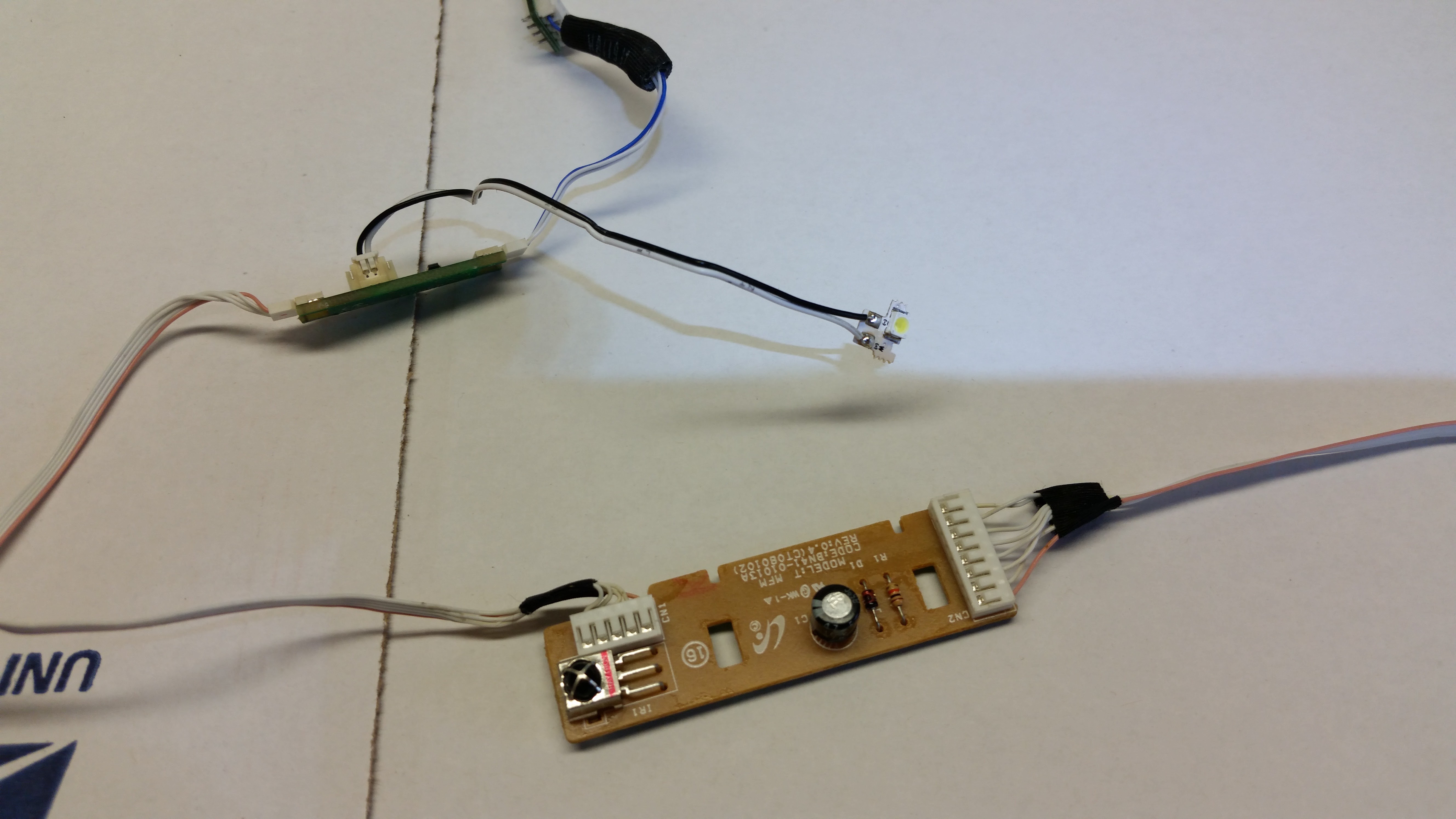
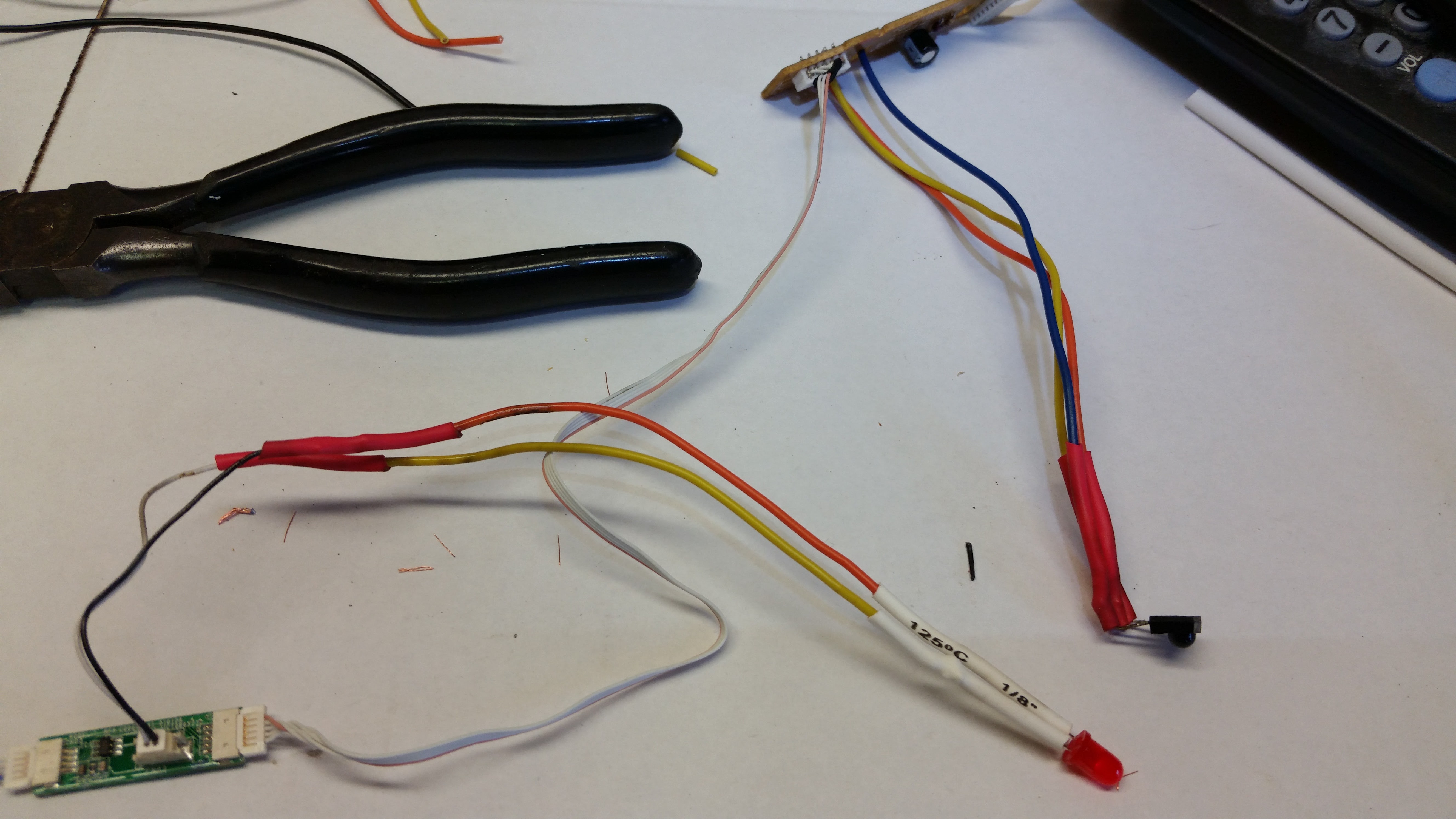
- Replace LED - The original power LED is square and white which is fine but I wanted to use a 5mm LED to allow easier mounted in a hole in the frame. Cut the original LED from the end of the wire lead. Strip both wires and solder about 6" of stranded wire to extend the length of each. Then solder the new 5mm LED at the end of the extended wires (a resistor is not needed), be sure the polarity is correct. Use heat shrink or electrical tape to insulate the solder joints.
- Extend IR Receiver - The IR receiver is soldered to a PCB which would make mounting in the frame difficult. De-solder it from the PCB and solder stranded wires to it. Then solder those wires to the PCB. Again, use heat shrink or electrical tape to insulate the solder joints.
Build IR Transmitter
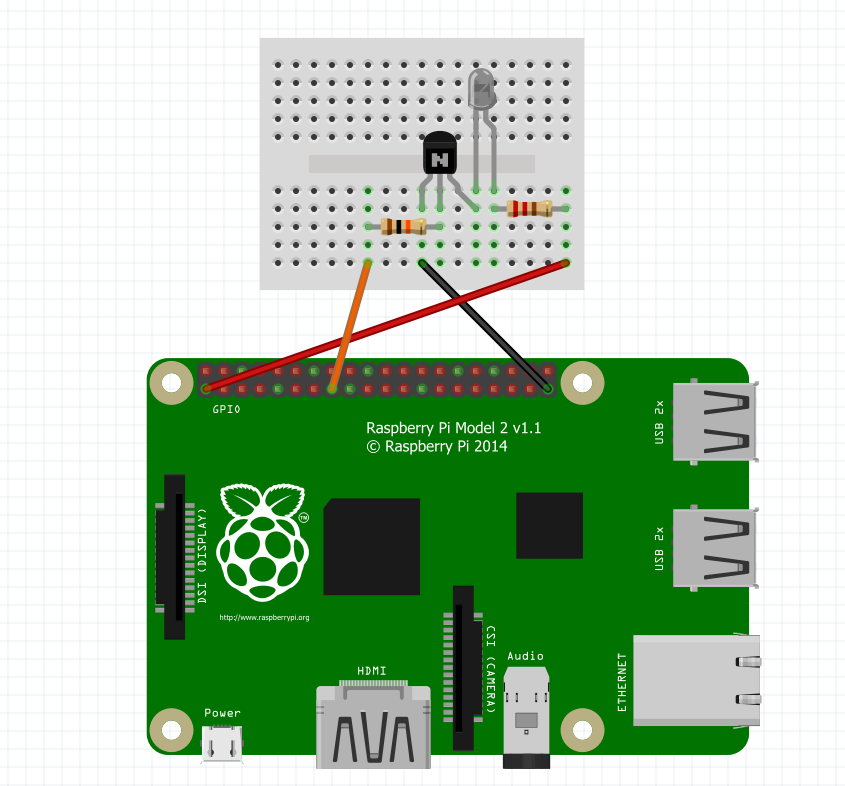
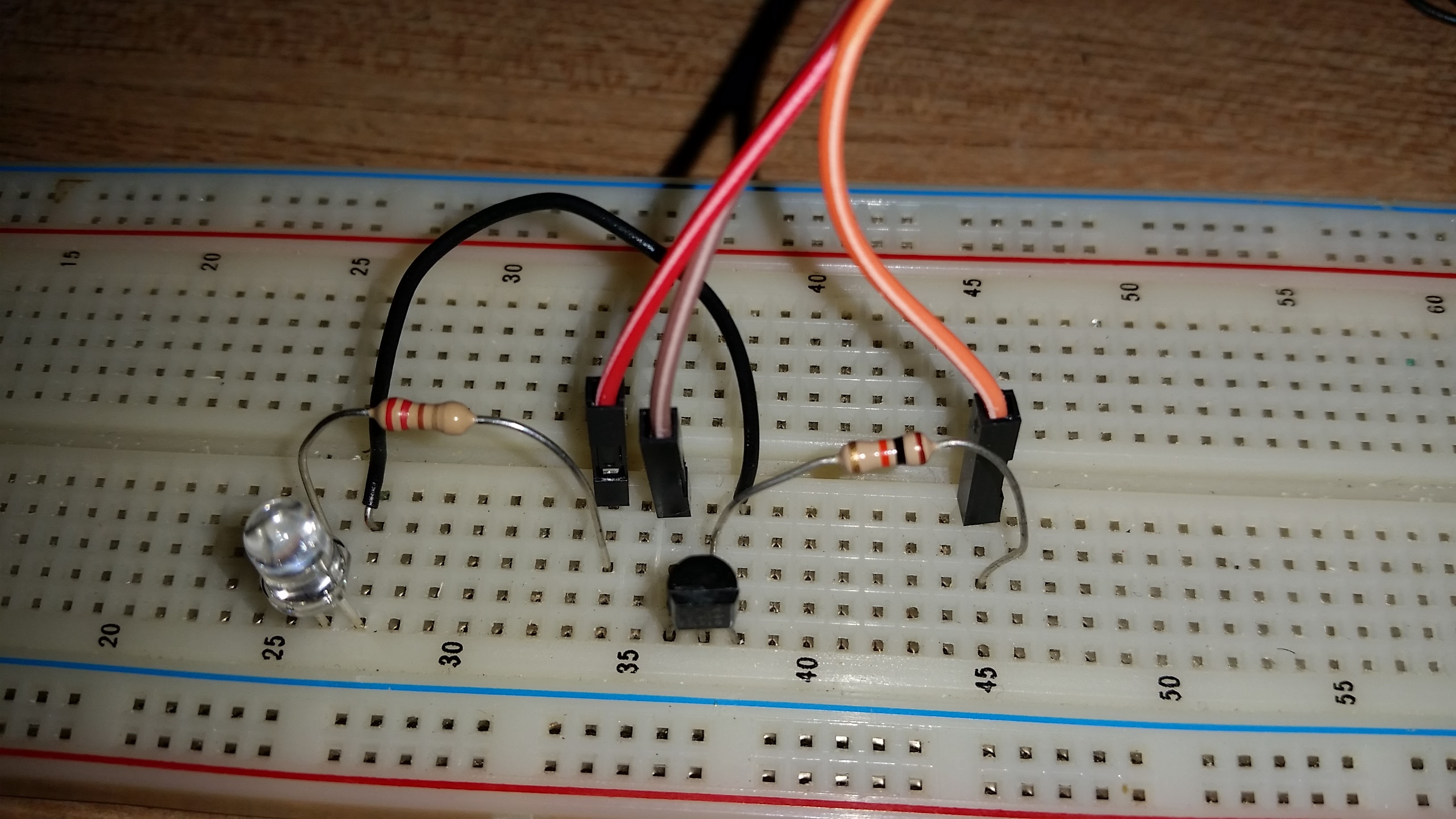
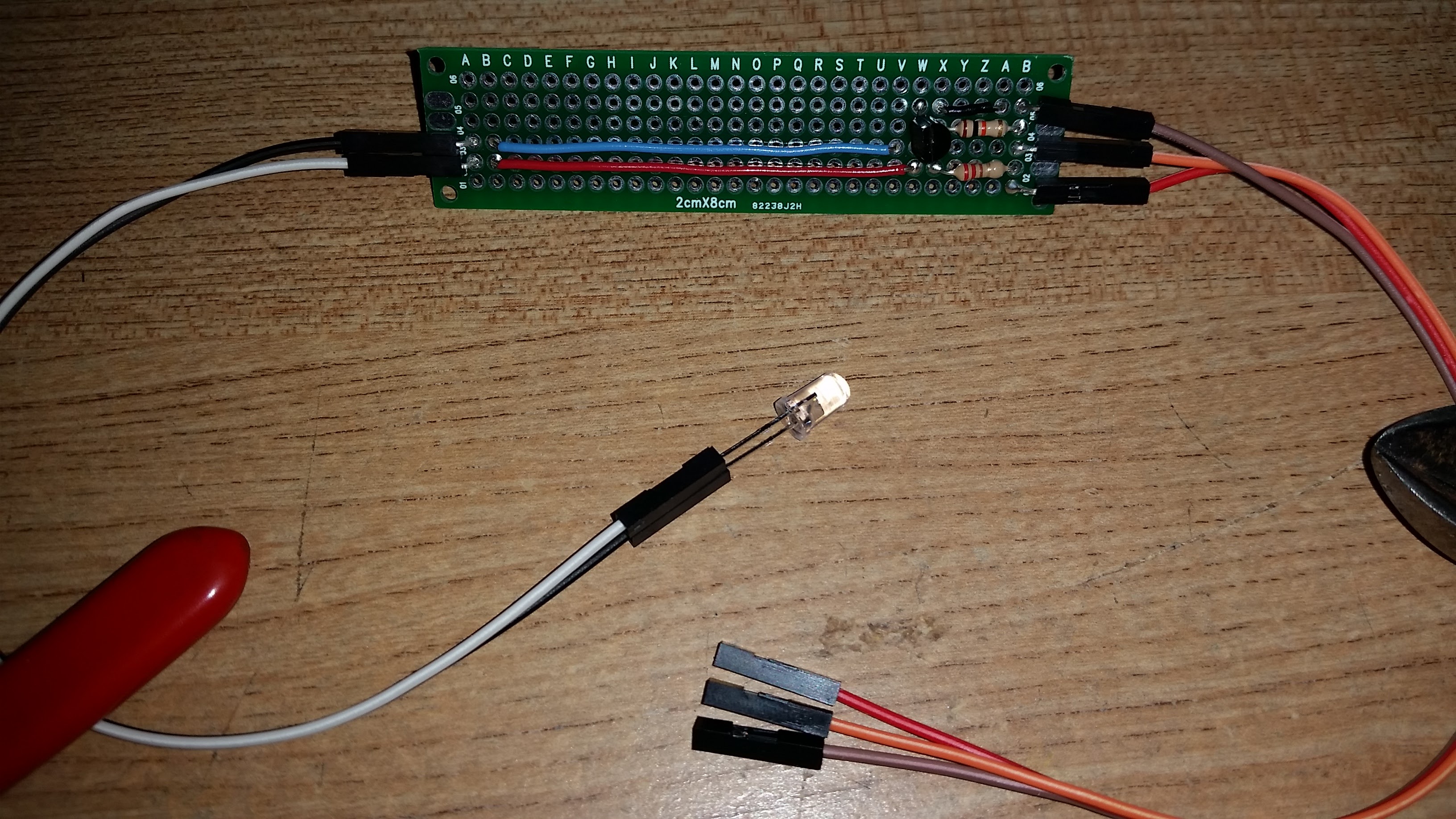
The transistor-powered IR transmitter will be built with the transistor, IR LED, jumper wires, prototyping PCB and two resistors listed in the materials step #2 . Additionally, you'll need a breadboard to prototype your IR transmitter. Wire the components as shown in the diagram on the breadboard. Once you are happy with your circuit transfer it to the prototyping PCB and solder in place. Use a pair of jumper wires to extend the IR LED from the PCB, do not solder the IR LED directly to the PCB. Use another 3 jumper wires as your connections to the Pi.
You can put the circuit to the side for now but if you want to test your IR transmitter you first need a functioning Raspberry Pi. You will have to skip ahead to Steps 16-17. These steps explain how to setup your PI and how to connect the IR transmitter. Once complete you can return to this step.
To test the IR transmitter circuit we can blink the LED with a script. Download the LEDblink script and move it to Pi's home directory. Replace *YOURPATH* below with the path to where the script was downloaded to. In the terminal type:
mv /*YOURPATH*/LEDblink /home/pi/
Then make it executable by running
chmod +x /home/pi/LEDblink
Run the LEDblink script
/home/pi/LEDblink
The IR LED is not a regular light-emitting diode and does not emit visible light but you can use a smartphone camera. to see it blink. Point the camera at the IR LED and look at the screen. If the circuit works, you should see the IR LED blinking.
Here is the LED blink script incase you are unable to download
#!/usr/bin/python
import RPi.GPIO as GPIO
import time
GPIO.setwarnings(False)
GPIO.setmode(GPIO.BCM)
GPIO.setup(22, GPIO.OUT)
while True:
    GPIO.output(22, True)
    time.sleep(1)
    GPIO.output(22, False)
    time.sleep(1)
Adapted from Raspberry Pi IR remote
Power the Pi
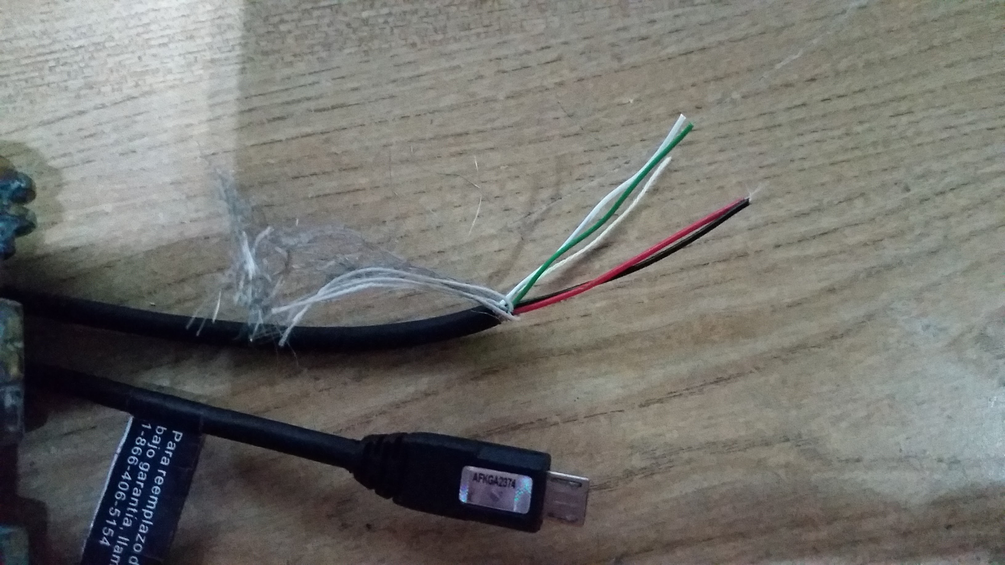
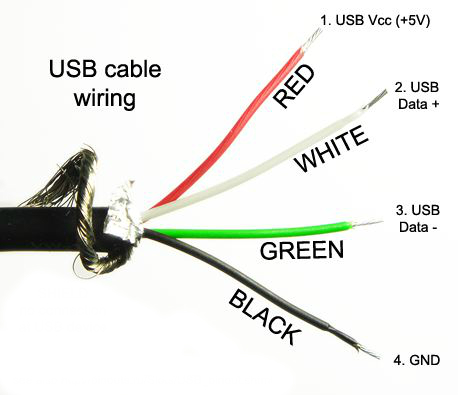
- Prepare USB cable - Cut the end off the sacrificial micro USB leaving the micro USB end and about 18" of length. Strip the wire. USB cables will have 4 conductors (usually red, green, white and black) and a shield. We will only be using the red +5v and black ground wires. The remaining wires can be trimmed out of the way.
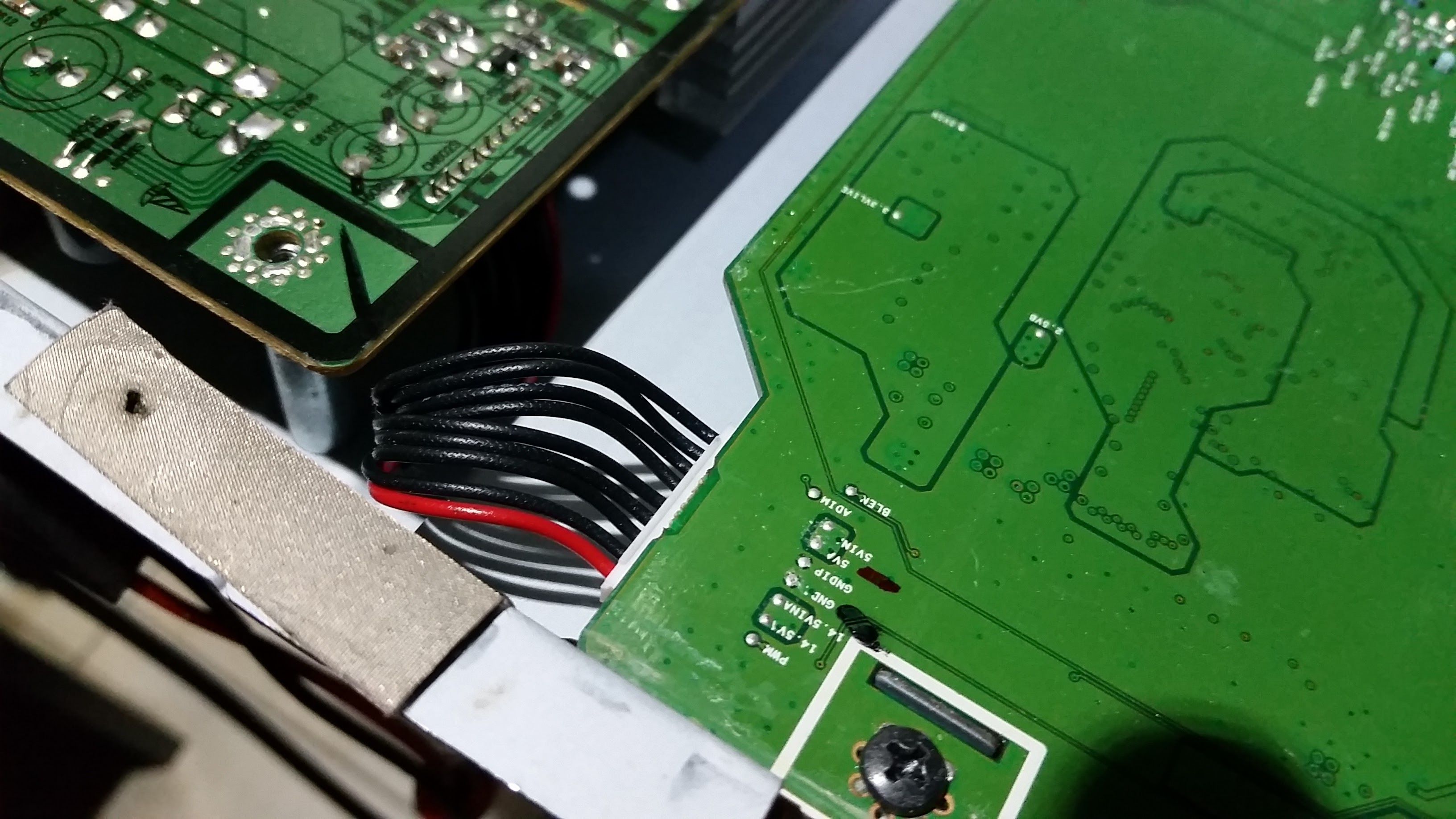
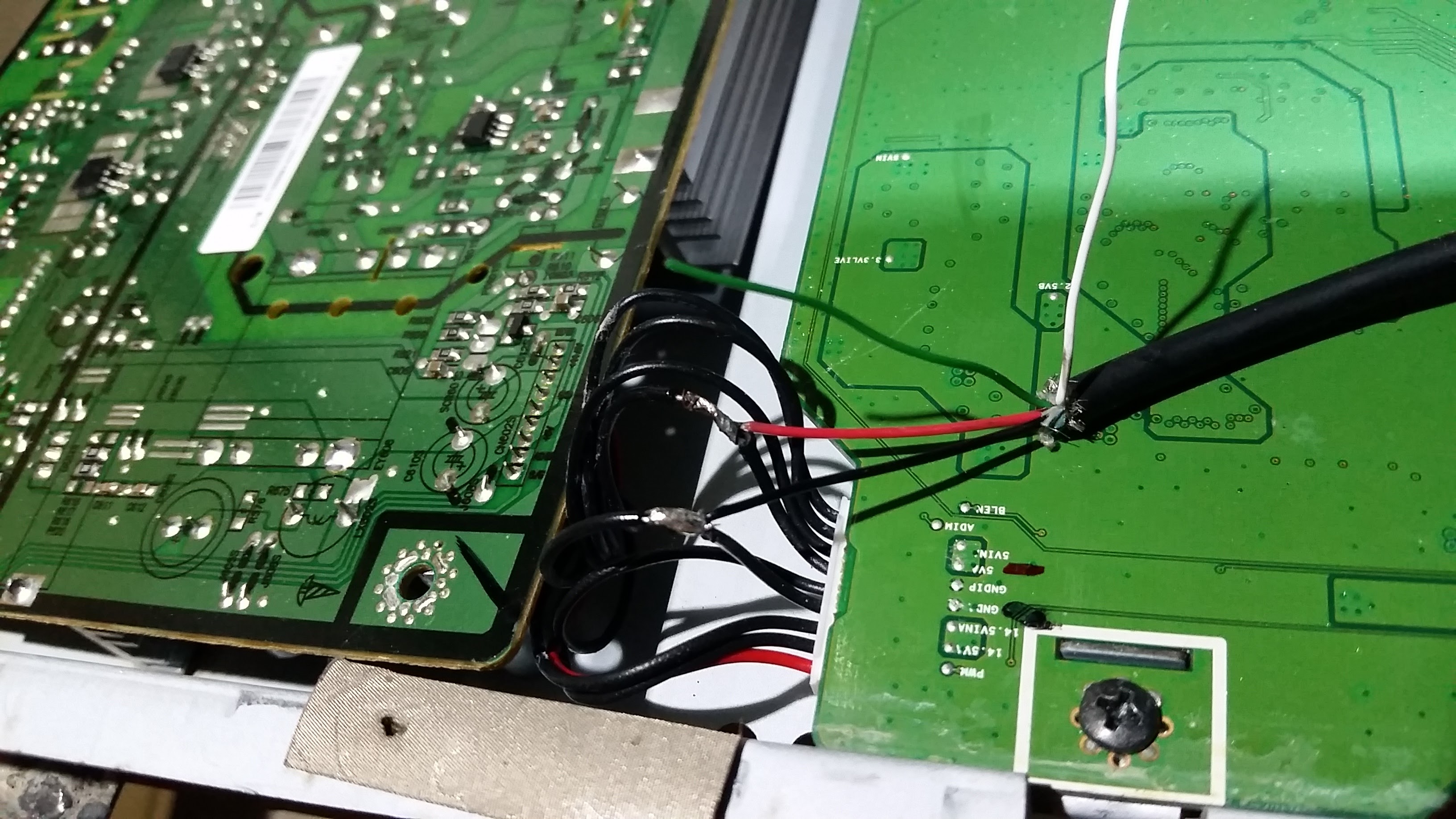
- Power Raspberry Pi - Locate the 9 wire harness between the power supply and the PCB, it will have 1 red wire and 8 black, This harness supplies a constant 5v (even when the LCD is off) to the PCB so we can use it to power the Raspberry Pi. We will number these wires 1-9 starting with the red wire. Splice by soldering the black wire from the USB cable to wire #4 and the red wire from the USB cable to wire #6. Use heat shrink or electrical tape to insulate the solder joints.
Mount Pi and Test
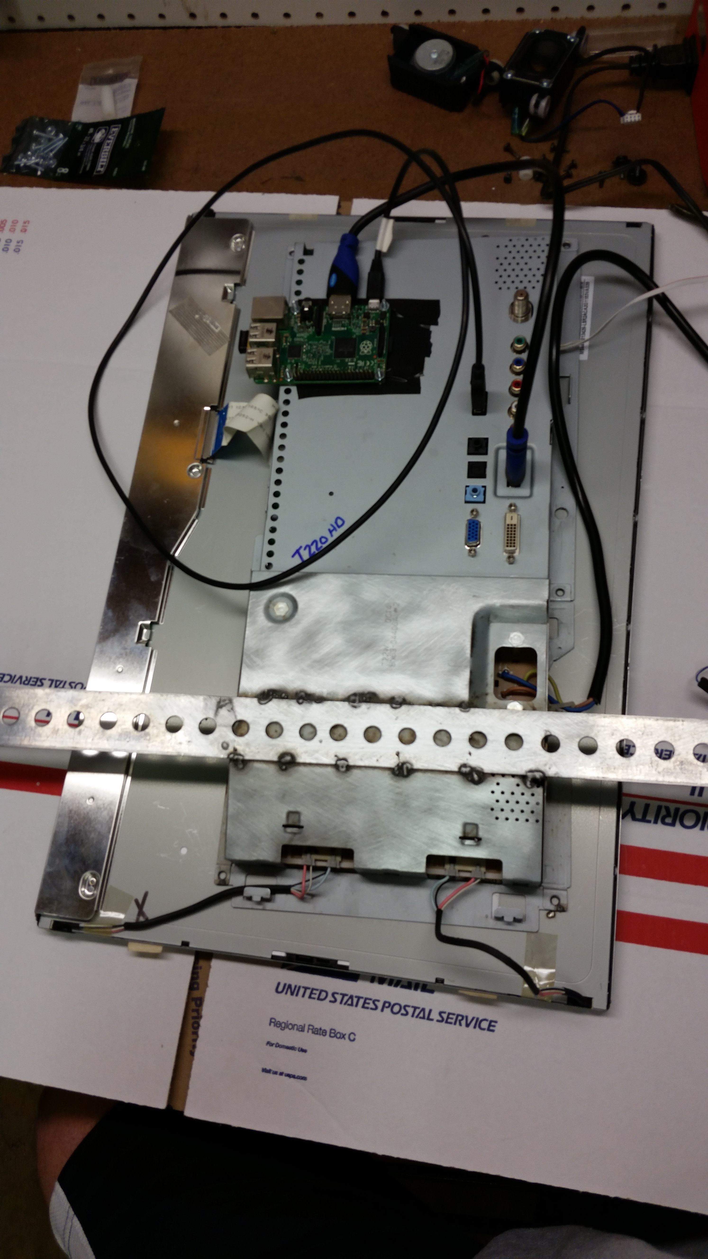
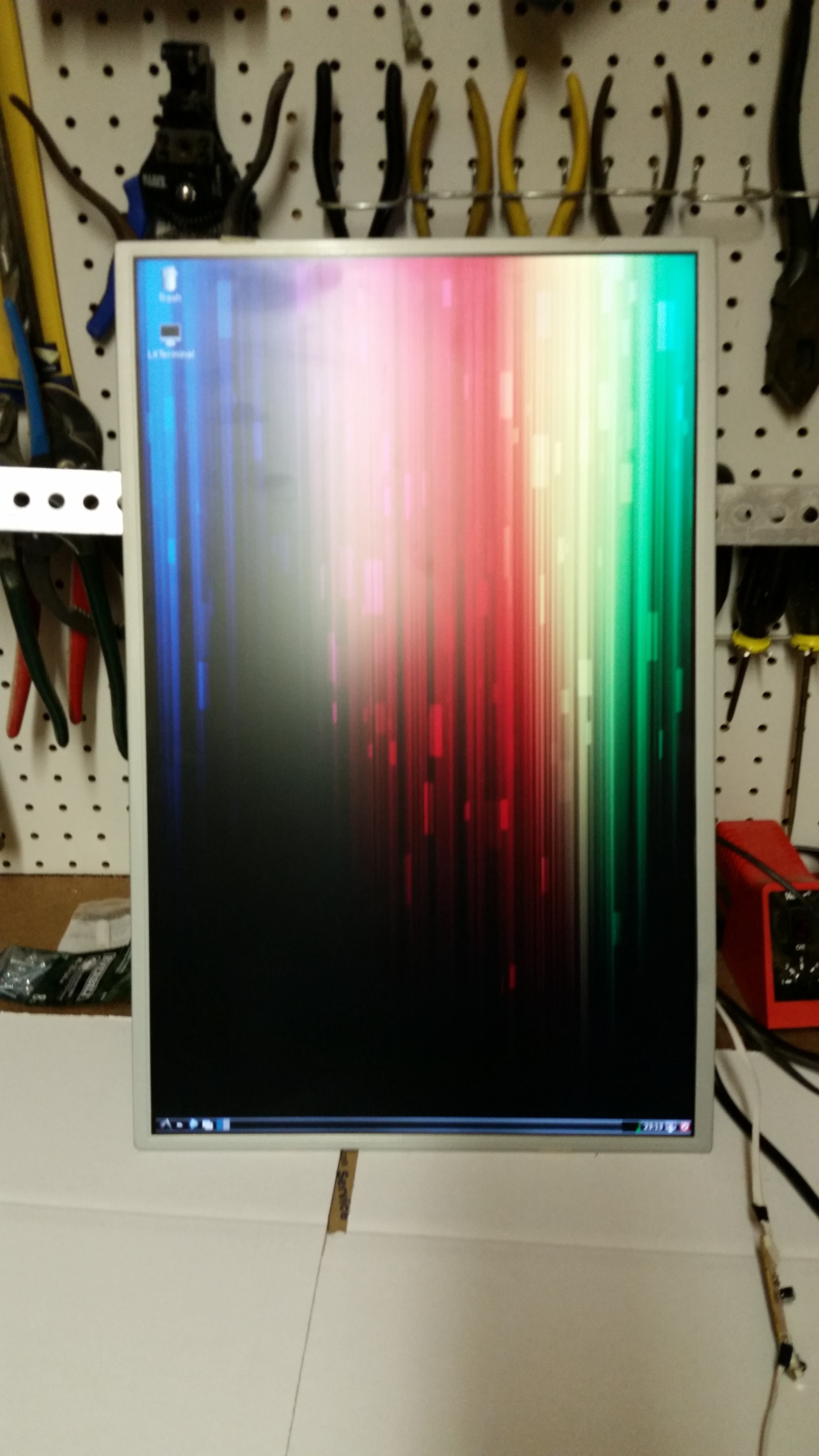
- Mount Pi - Drill 4 holes in the tray to mount the Raspberry Pi. Use screws and standoffs to secure as show in pictures. Take care that you have enough clearance between the screw heads and the PCB once it is reinstalled to avoid short circuits.
- Reassemble - Install the power supply and PCB back into the tray securing with original screws. Route the new power and micro USB cables out of the side of the tray. If you would like to bench test at this point continue connecting the remaining cables as described in Step #16, otherwise keep the LCD separate from the tray for now.
Create Frame
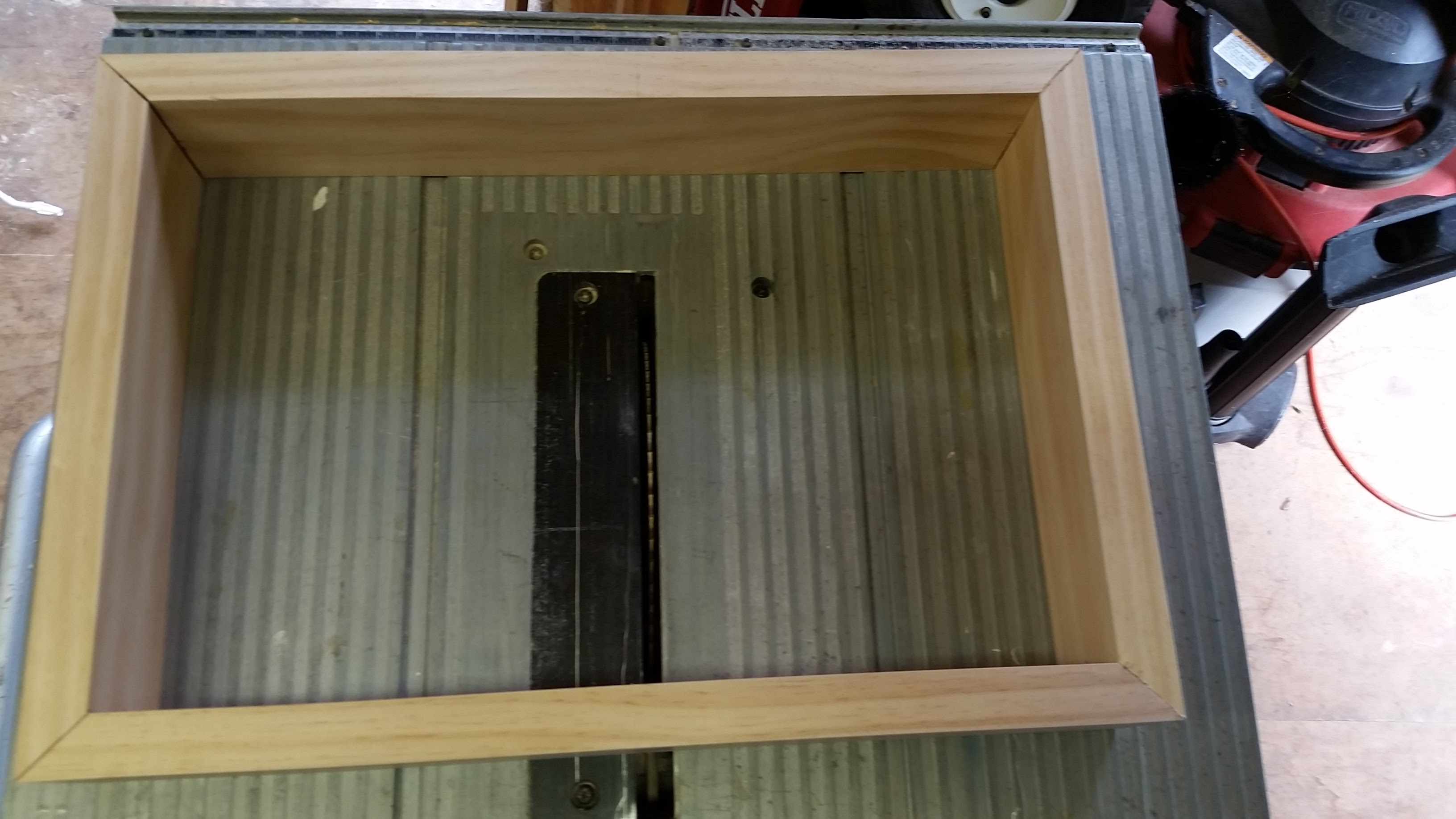
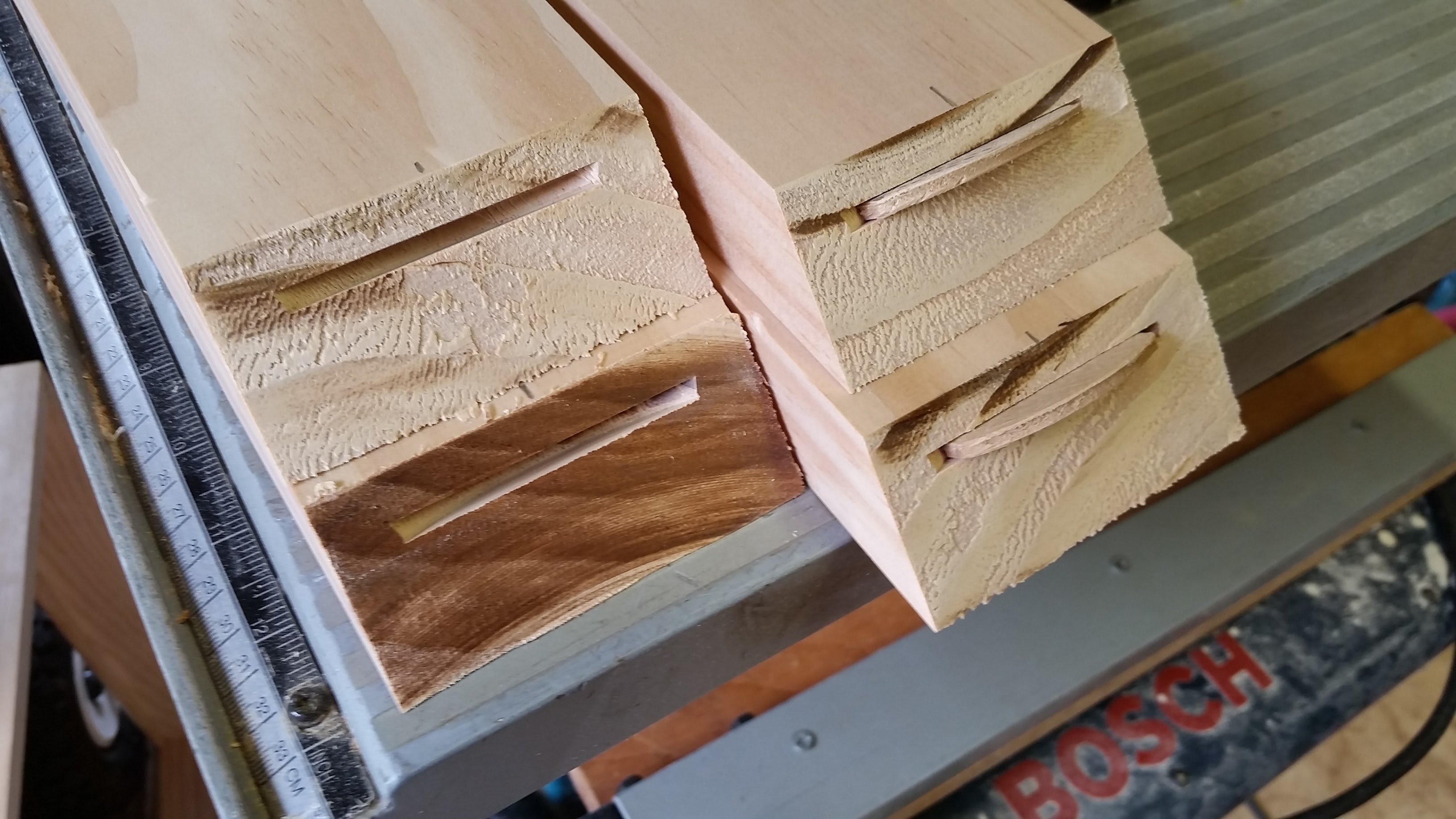
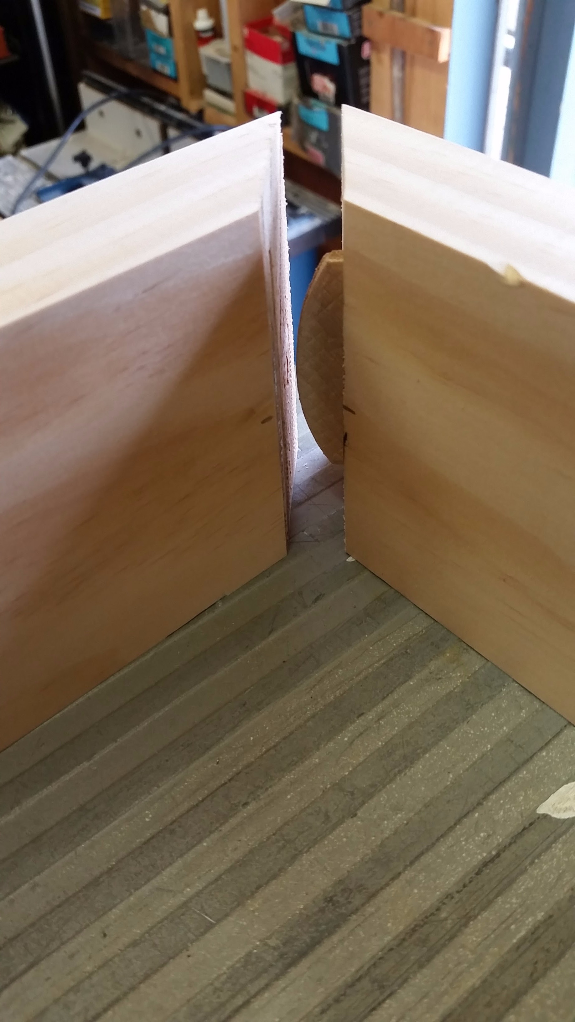
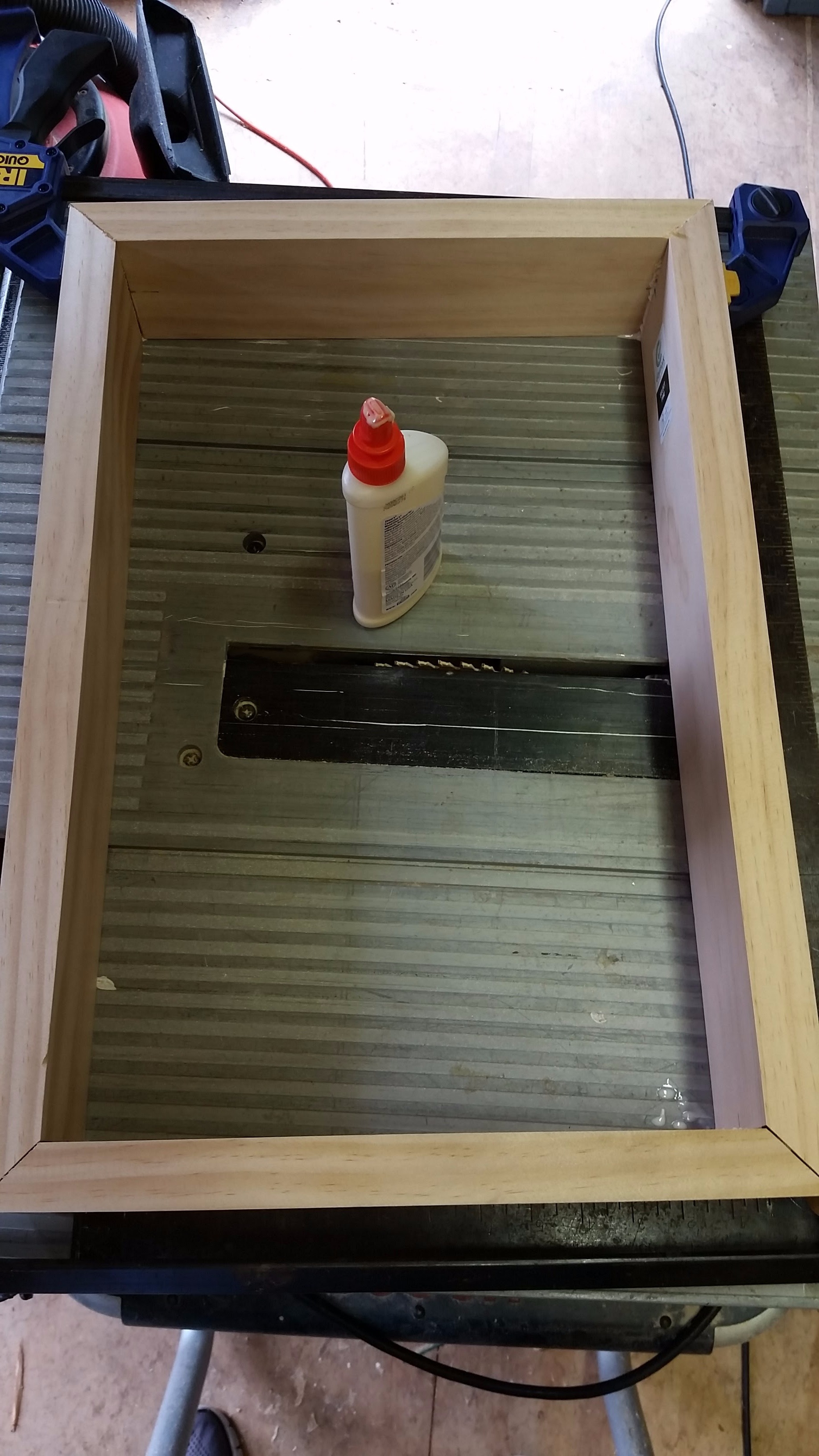
Steps 9-12 describe how to create a new wood frame for all the components. Basically it's a picture frame for the LCD.
- Create Frame - Using a miter saw, cut the 5/4" x 3-1/2" pine into 4 pieces with 45° cuts on each end to form a rectangle around the LCD. This should fit snugly around the LCD but not so you have to force the LCD into the frame.
- Join Frame - Mark the centers of each cut end. Set up your biscuit joiner for 45° and #10 biscuits, set the depth of the cut to be centered in the joint. Cut all 8 biscuit slots.
- Glue Frame - Insert biscuits in slots, do not glue yet, and test fit with LCD. If the LCD fits correctly in the frame, remove it and use wood glue on the biscuits and 45° ends to join the frame together. Making sure the frame is square use clamps while the glue sets. Wipe off any excess wood glue.
Here is another Instructable with more tips for building a picture frame with biscuit joinery by Canida
Trim Frame
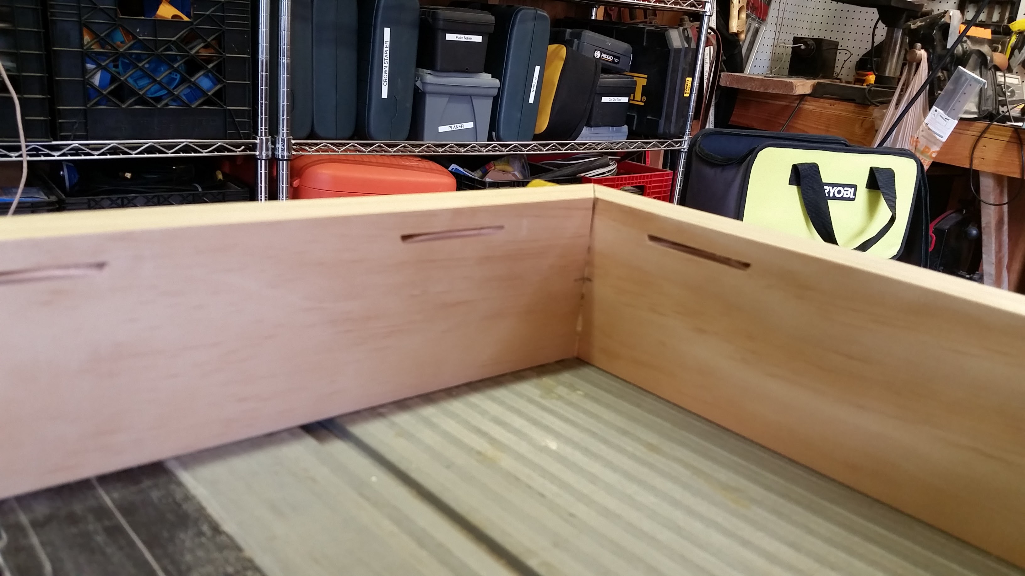
- LCD Support - Now cut some biscuit slots to hold the LCD in the frame against the stop moulding that will be installed next. Set the biscuit joiner to 90°. Measure the thickness of the LCD with a caliper and set the depth of the joiner to the same. This LCD has 1 side that is thicker then the others so cut the biscuit slots for the thinner 3 sides first. 2 biscuits on the inside of the short sides of the frame and 3 each in the long sides. After cutting those 7 slots, measure the thicker side of the LCD and set the depth of the joiner the same. Cut the last 3 biscuit slots. The biscuits should fit snugly, they hold the LCD in place without glue.
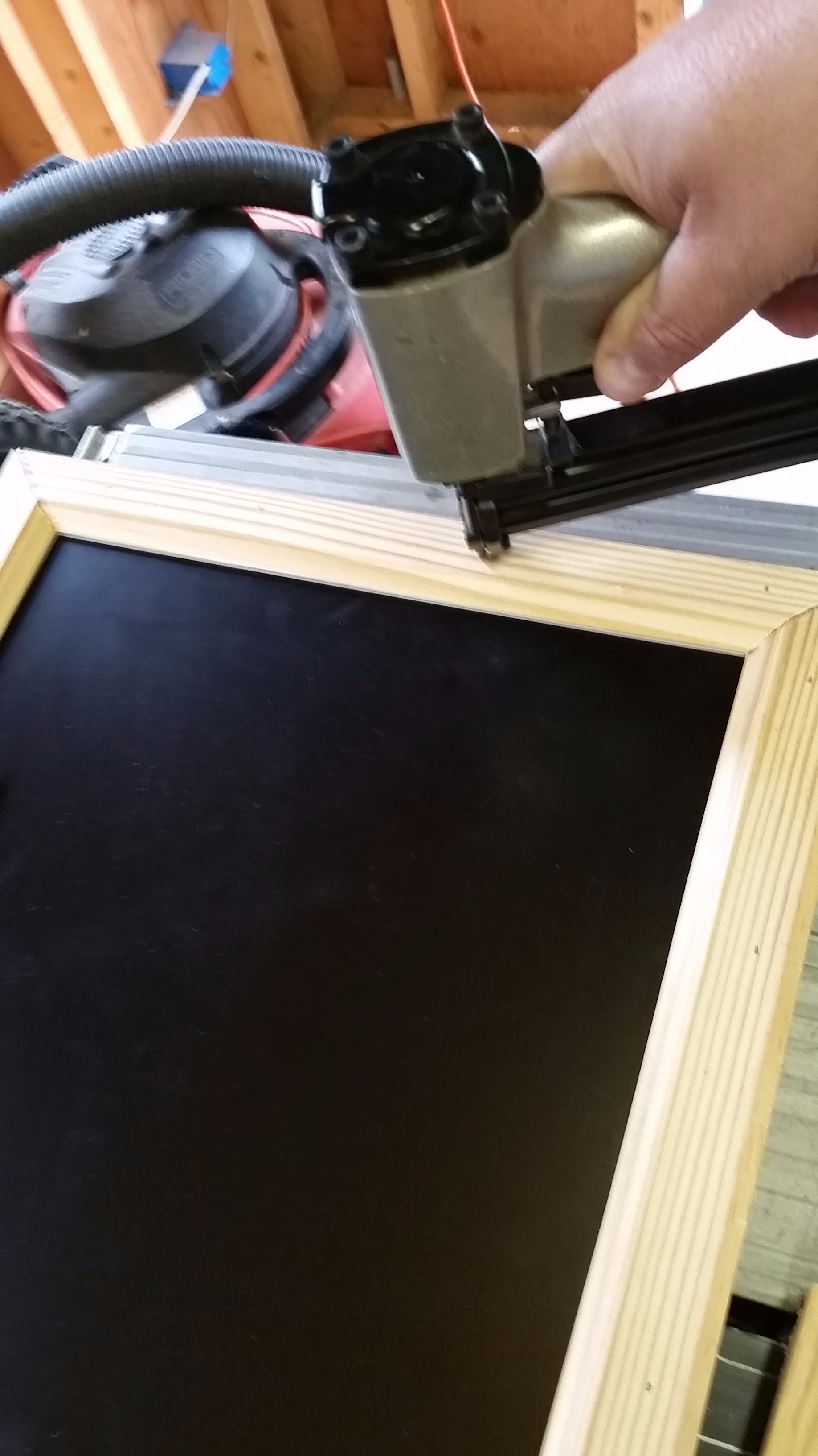
- Trim - Cut the stop moulding into 4 pieces with 45° cuts. The inside edge (thinner edge) will over hang the inside of the frame and cover the metal bezel of the LCD. Use the LCD as a guide to determine the correct overhang. The outside edge of the stop moulding will be about 1/4" from the outside edge of the frame, It creates a 1/4" reveal around the entire frame. I originally planned on routing a contoured edge into the outside corner and removing the reveal but I liked the look with the 1/4" reveal so I left it as is. Secure with wood glue and pneumatic finish nailer.
Route
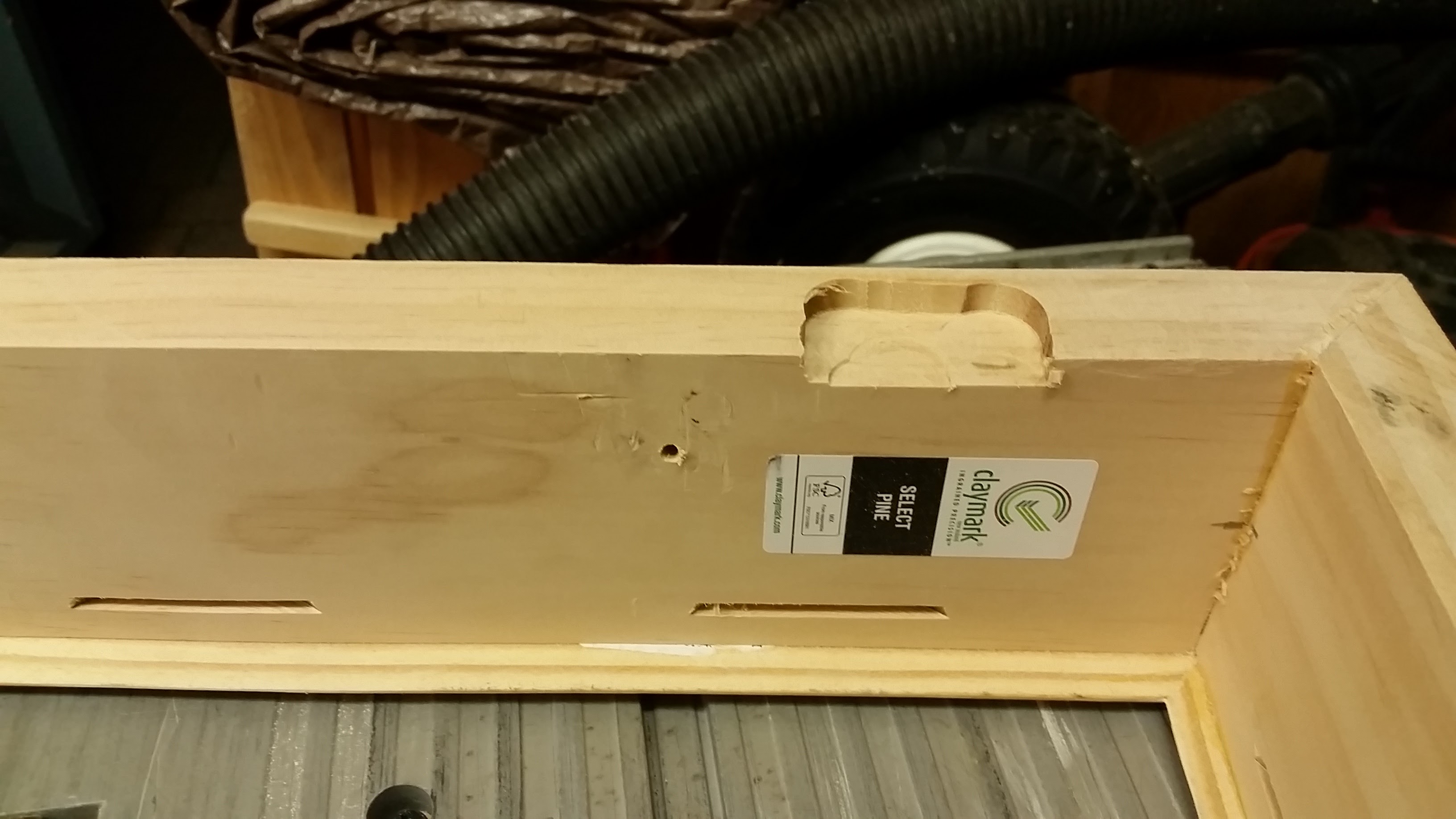
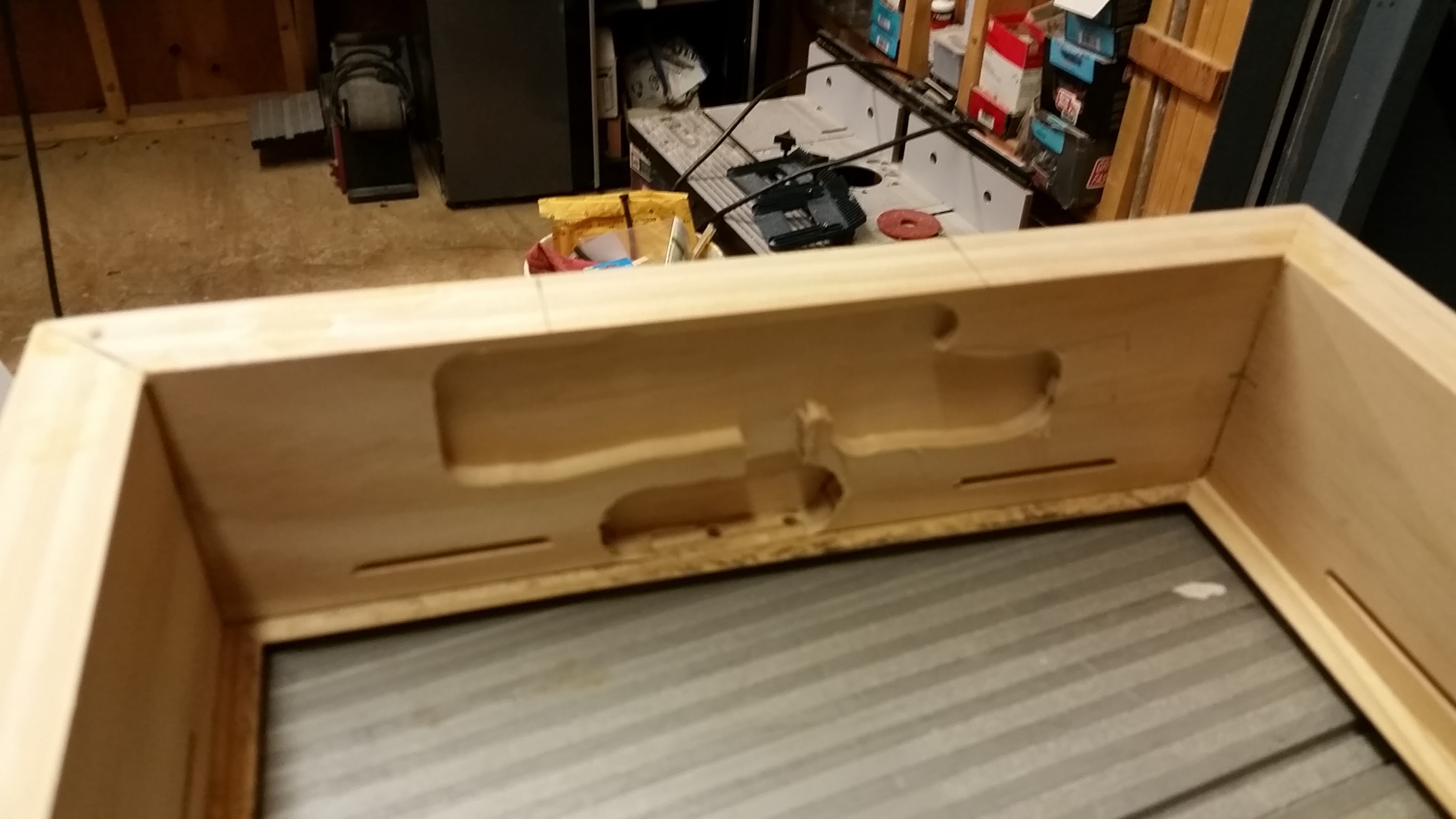
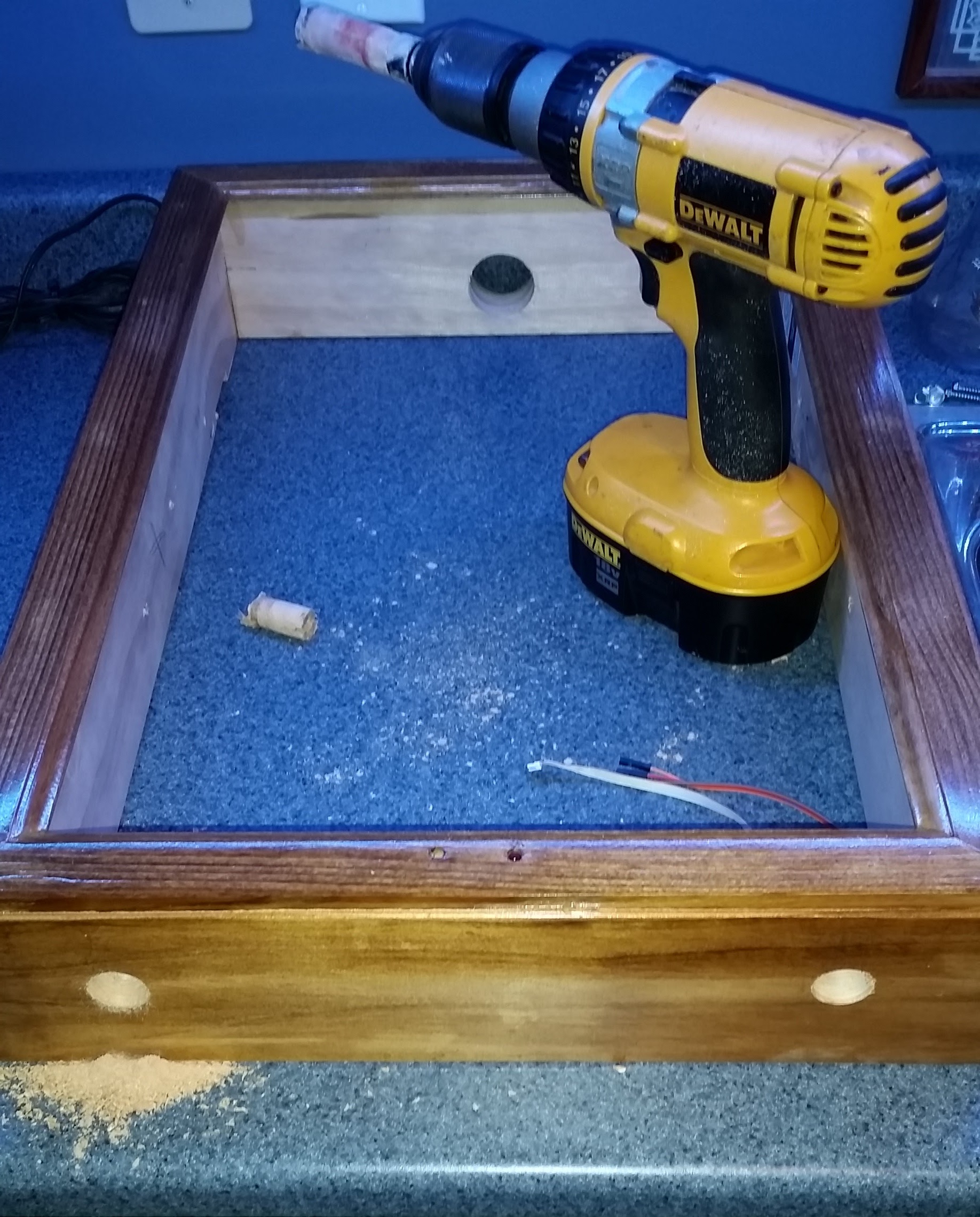
- Recess French Cleat - Cut the frame side of the French Cleat so it is 1/2" narrower then the width of the frame. Mark the outline of the cleat about 3" from the top on each side of the frame. Set the depth on your router to the the same as the depth of the French cleat. Route out a recess on the back of the frame so that the cleat will sit flush with the back of the frame. Cut the wall side of cleat to fit inside the width of the frame. This will ensure the frame mounts flush to the wall.
- Recess Factory Electronics - At the bottom of the frame create a recess with the router to hold the factory electronics (IR PCB, factory switches, power LED) and IR transmitter PCB from Step #6. Be sure you have enough length for the wire to reach their connector on the side of the tray. Drill two 3/16" holes from the bottom of the frame into this recess. These holes will hold the 5mm LED and IR receiver and allow their wires to run back to the factory harness.
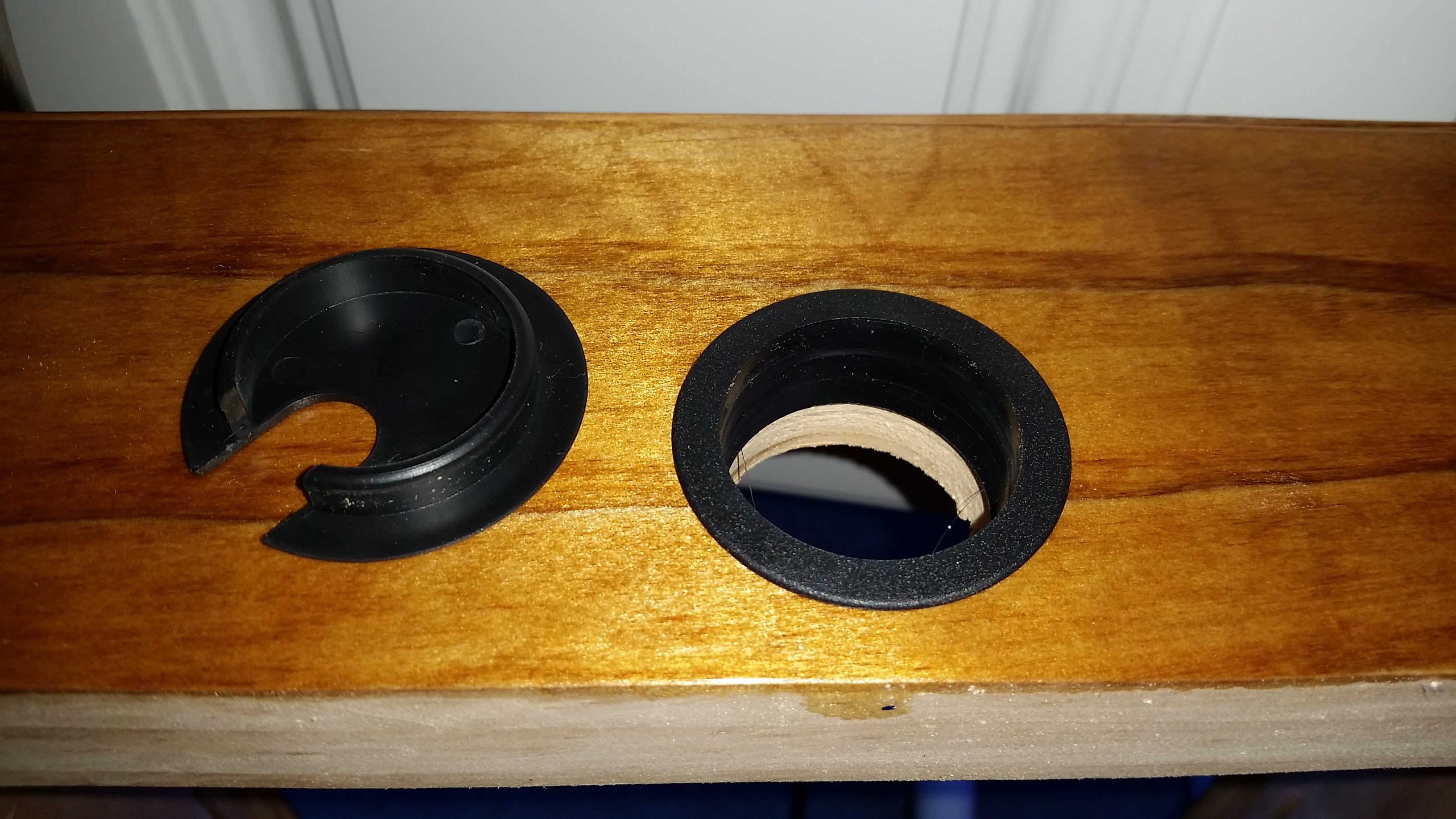
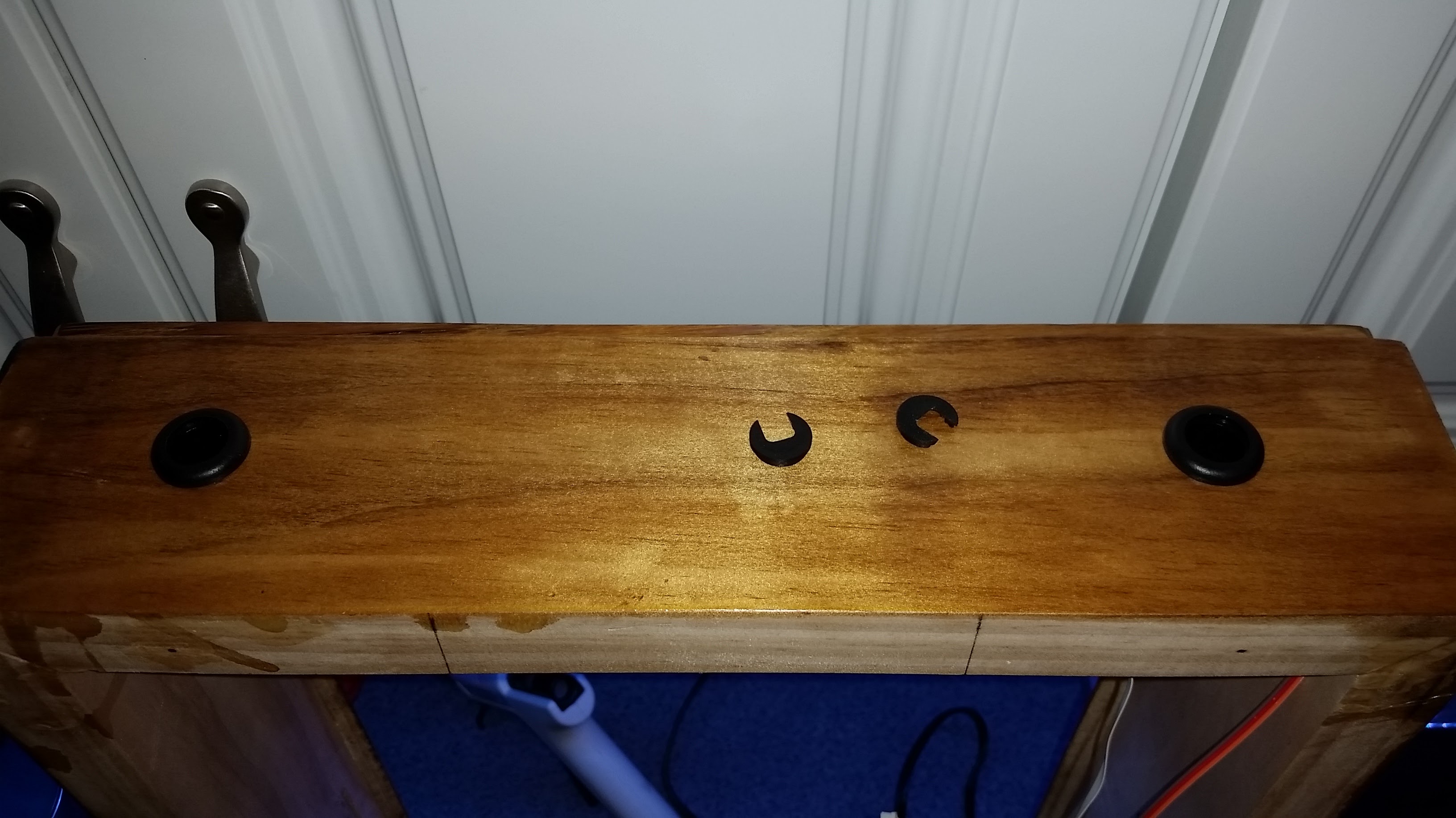
- Drill Ventilation Holes - With the 1-1/2" hole saw, drill one hole centered at the top of the frame, then drill two 3/4" at the bottom of the frame with the 3/4" hole saw. Be sure to avoid the area you routed out in the previous step. Unlike my picture, you will drill these before staining or painting.
Finish Frame
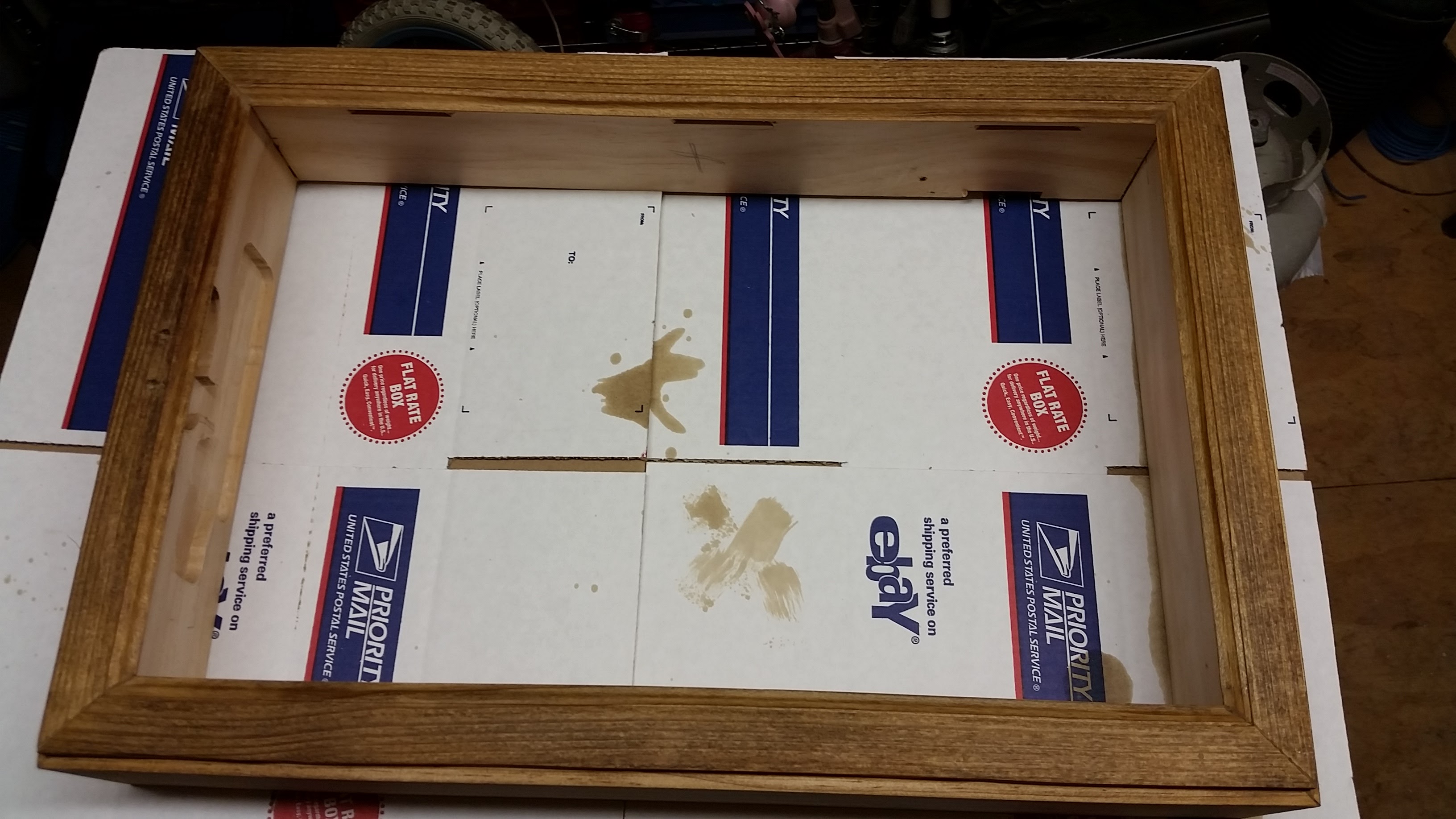
- Prep - Fill all nail holes and joints with wood putty and allow to set then sand the outside of frame with your random orbit sander. Sand until smooth using at least 220 grit sand paper.
- Finish - Stain the frame with your favorite shade of wood stain, then apply 3 coats of polyurethane, sanding between each coat. Or if you prefer, paint. Follow the manufacturers directions for time between coats.
Assemble
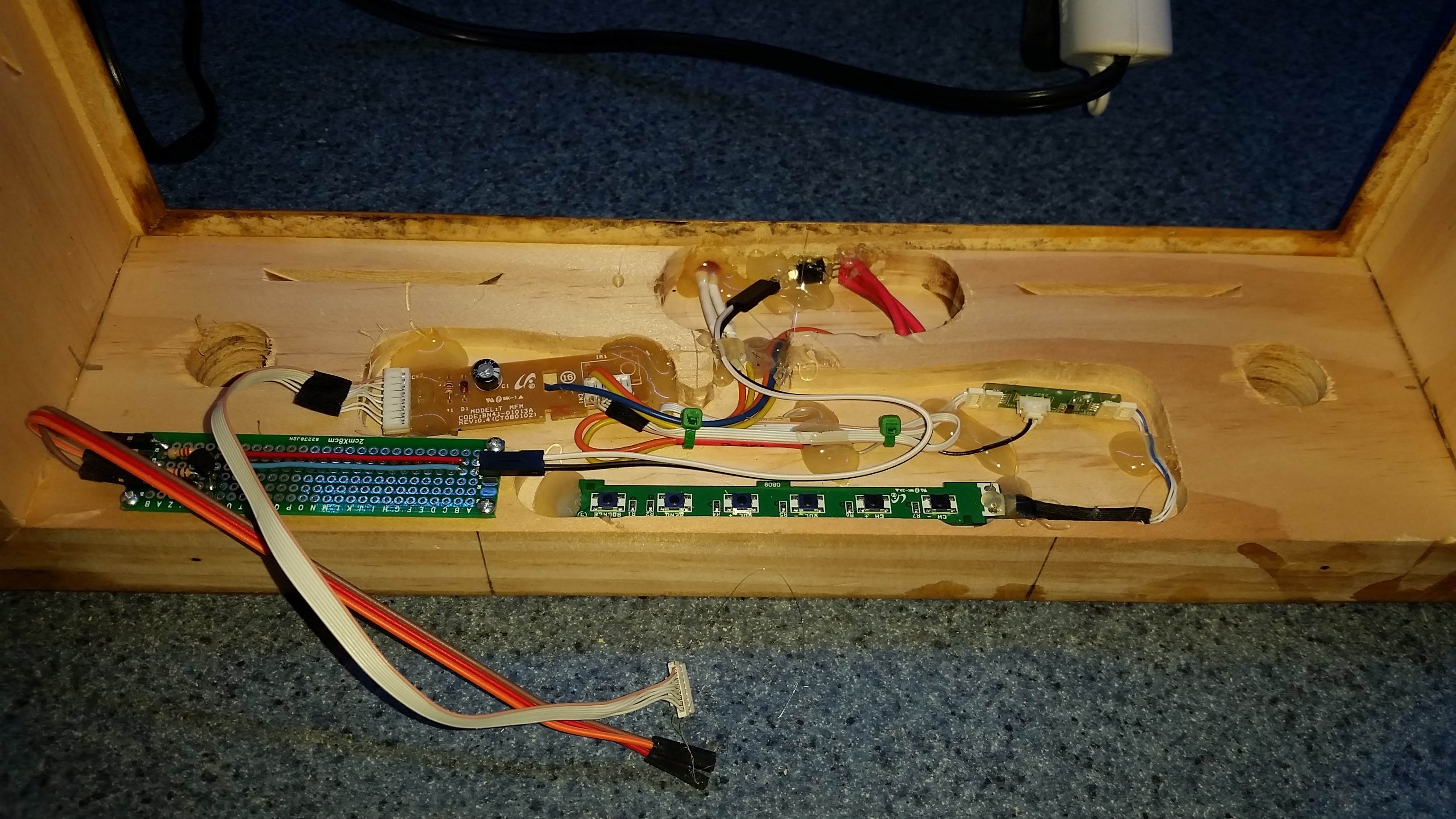
Now it's time to put it all together.
- Start by inserting the power LED into its hole, the top of the LED should be flush with the front of the frame. Next add the IR receiver it will be secured to the back of the other hole due to its square shape. Then place the IR transmitter built in Step #6 next to the IR receiver so it aims directly at its side. Hot glue in place.
- Place the factory electronics (IR PCB, factory switches, power switch) into the routed area of the frame from Step #11 and route the wires so they will be out of the way. Be sure you have enough length for the factory harness to reach its connector on the side of the tray once installed. Hot glue in place.
- Install the IR transmitter PCB built in step #6 in the routed area and hot glue in place or secure with screws to the frame.
- Install the three grommets in the ventilation holes and secure with a little bit of hot blue.
Install LCD and Tray
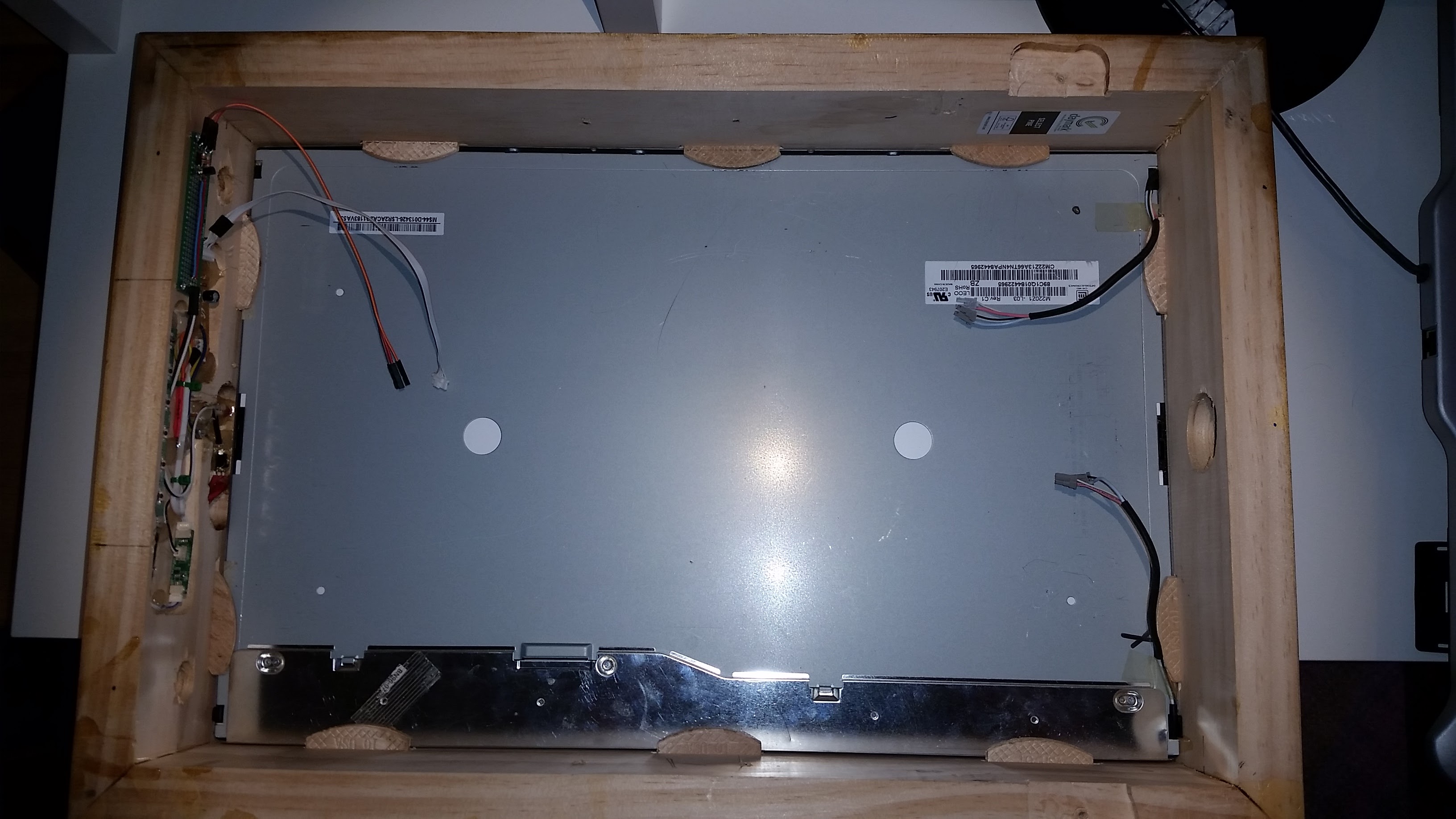
- Place the LCD in the frame and secure with #10 biscuits. They should be snug and hold the LCD without using wood glue.
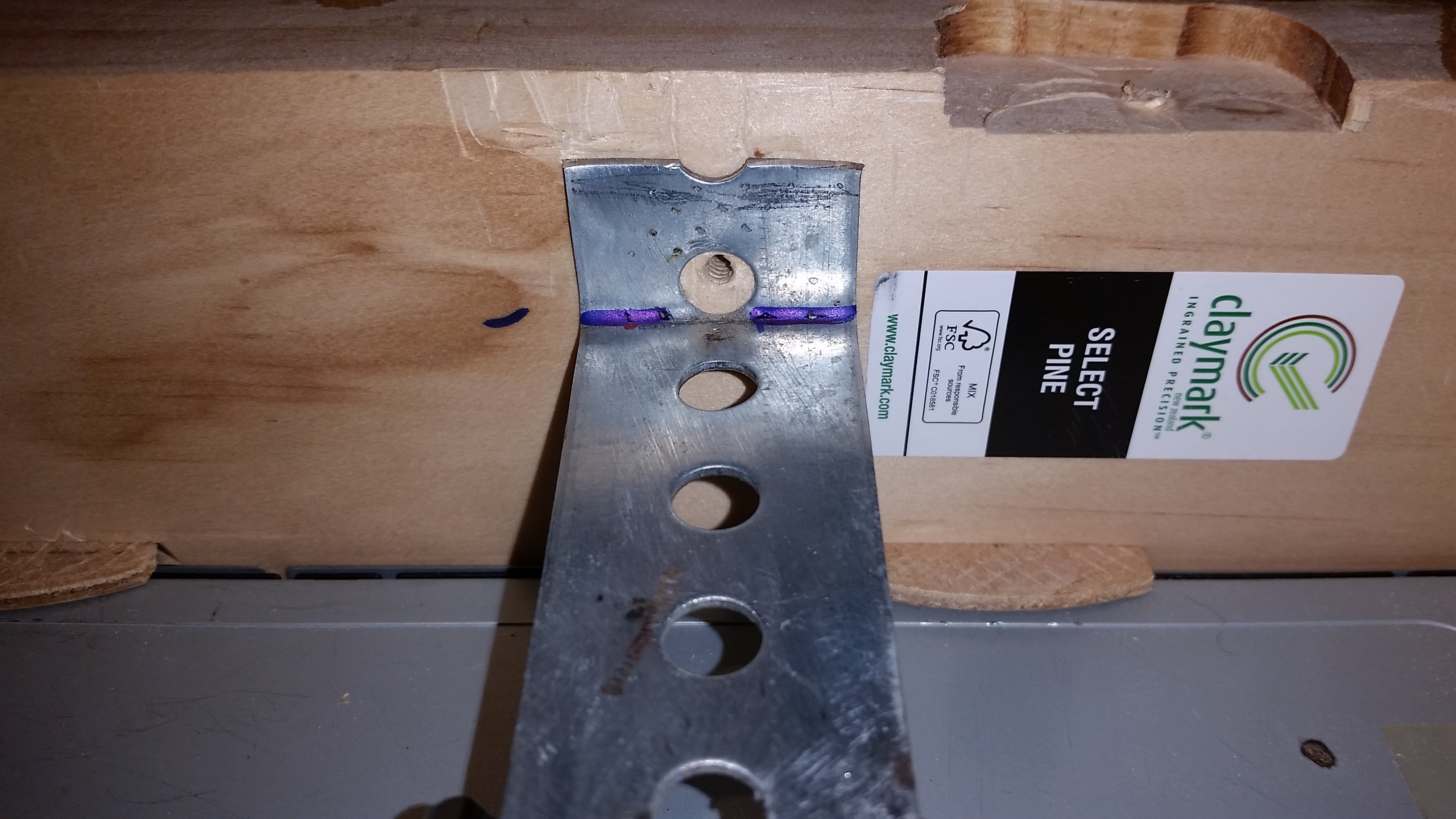
- Next place the tray with the welded steel flat bar support across the back of the frame. Mark the width on each end of the steel flat bar. Bend the steel flat bar in a vise to 90° at the marks. Trim off excess steel flat bar about 1" past the bend on each end or enough so it doesn't extend beyond the back of the frame and secure with wood screws.
Fan, French Cleat and Speakers
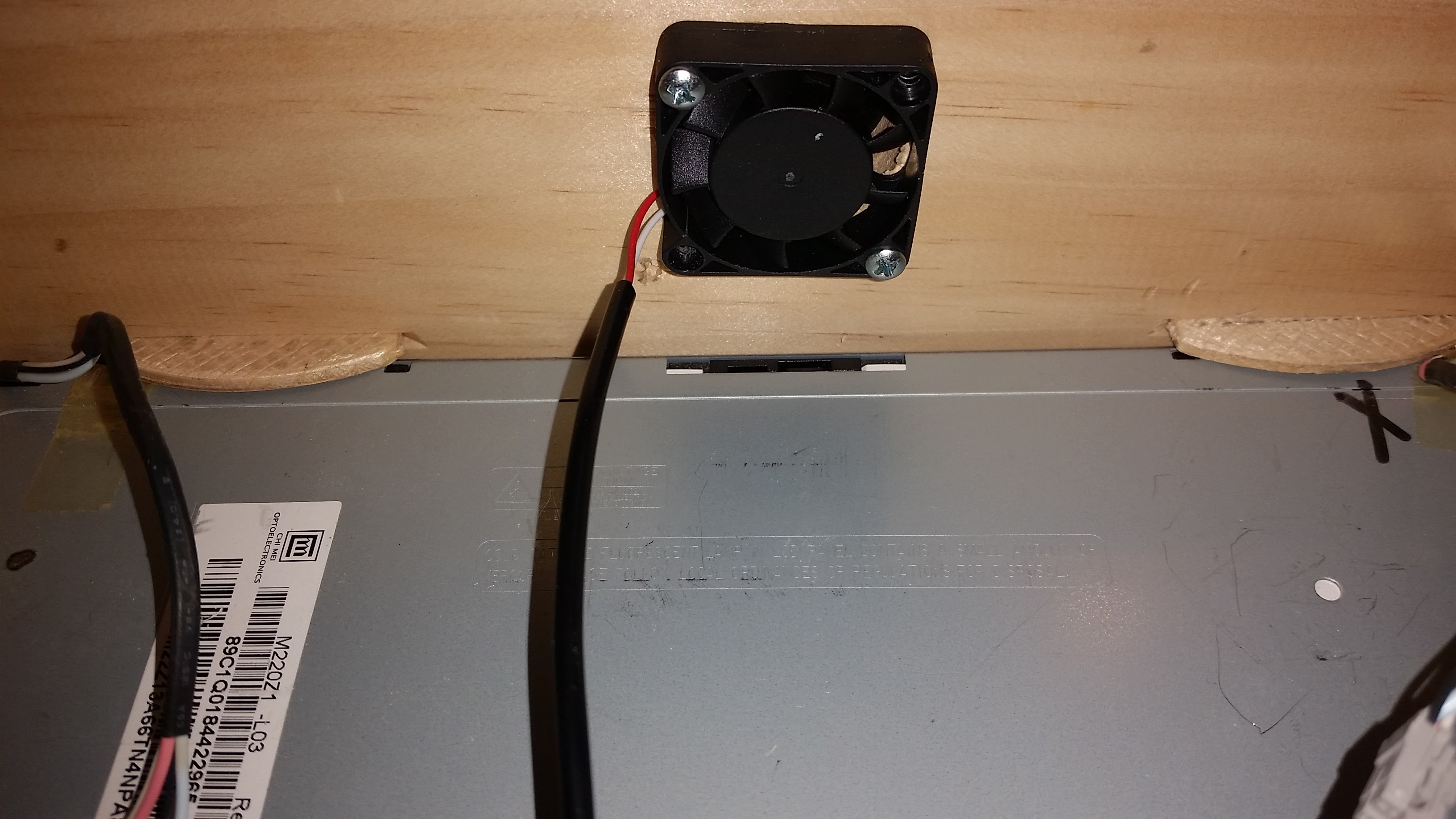
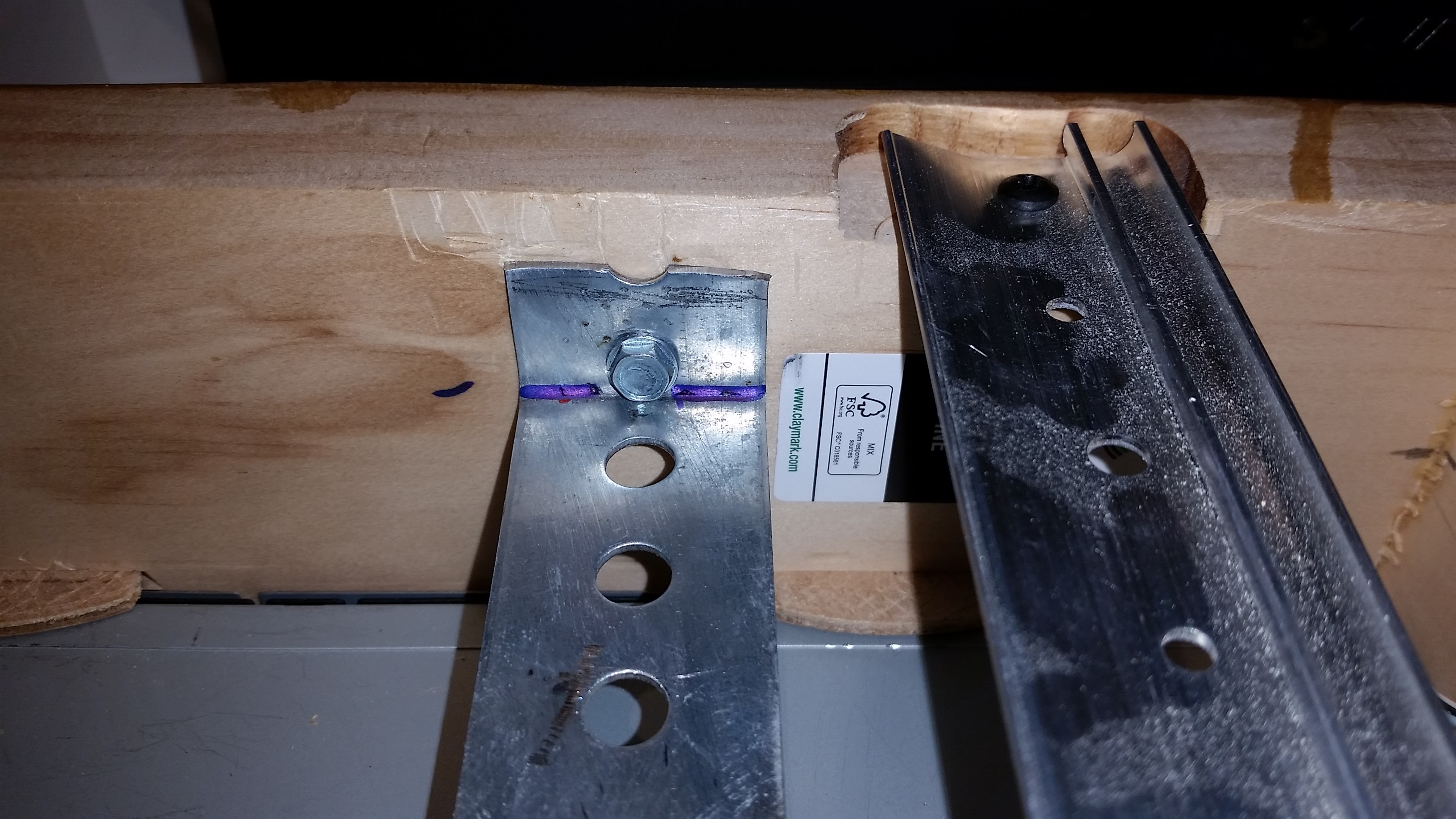
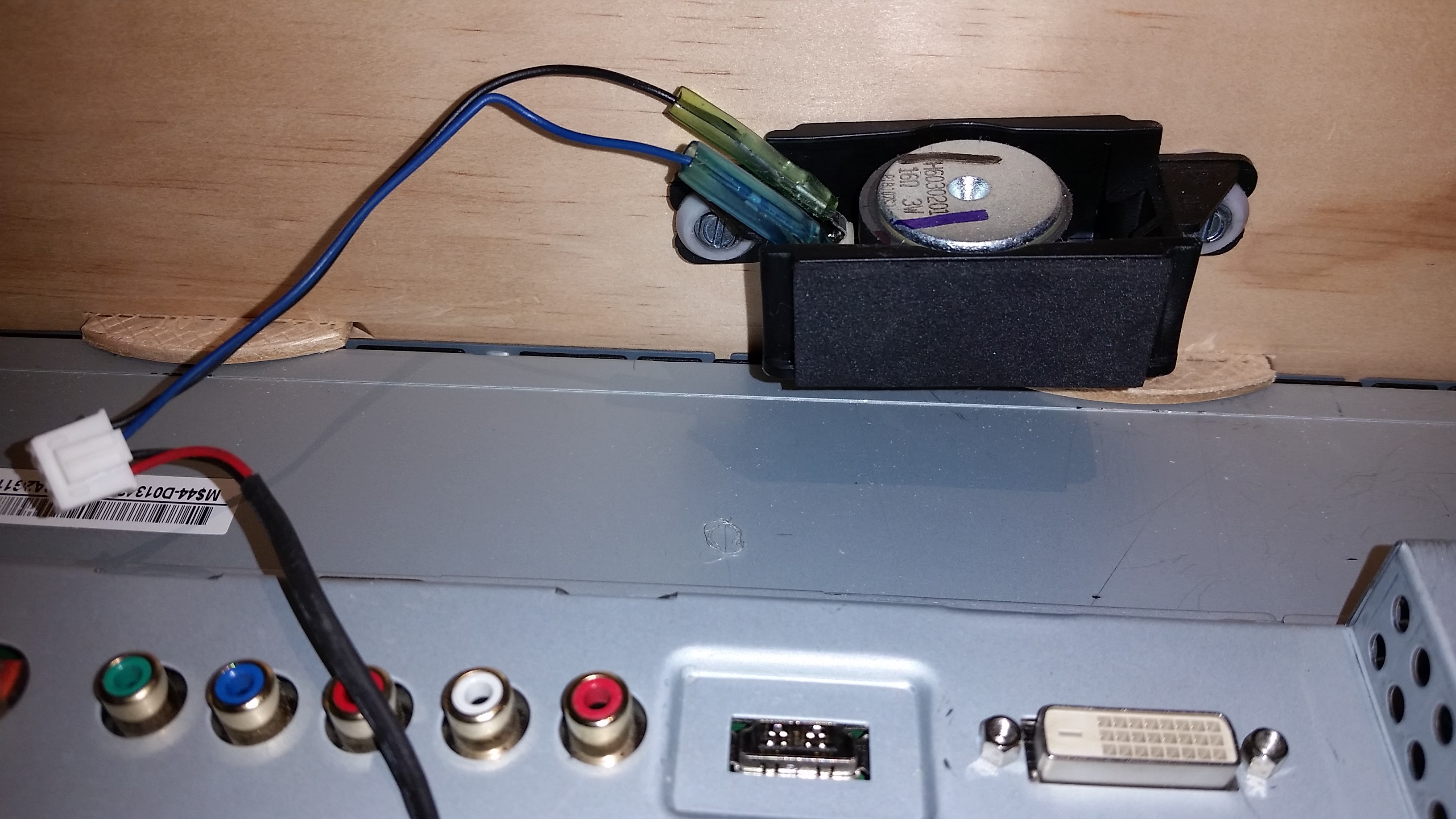
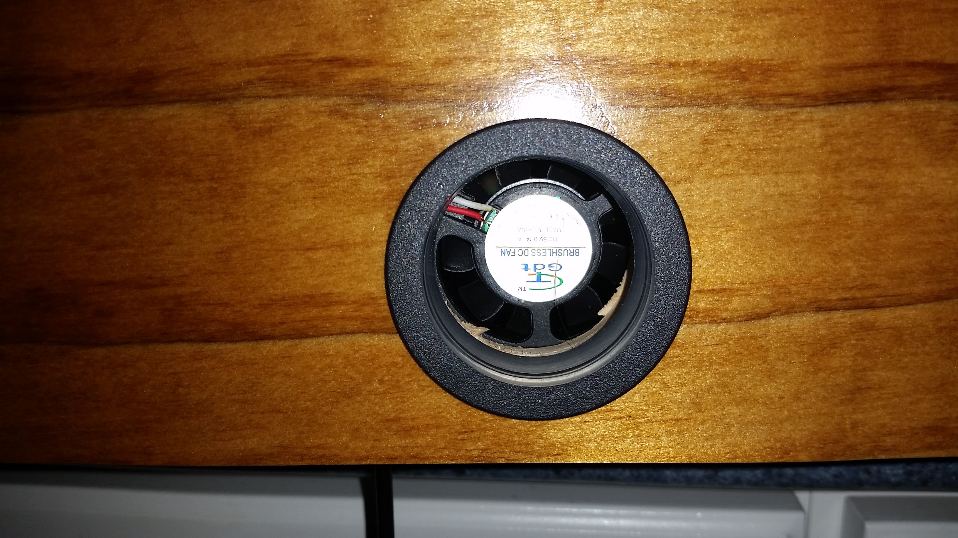
- Install the 40mm fan inside the 1-1/2" ventilation hole with screws so that the it pulls air from inside the frame and exhausts to the outside.
- Install the French Cleat in the recesses created in Step #11 with the screws provided making sure it will be level with the top of the frame.
- Secure the two speakers removed in the disassembly to either side of the rear of the frame with wood screws. Leave enough length so the wire can reach the factory connector.
Connect
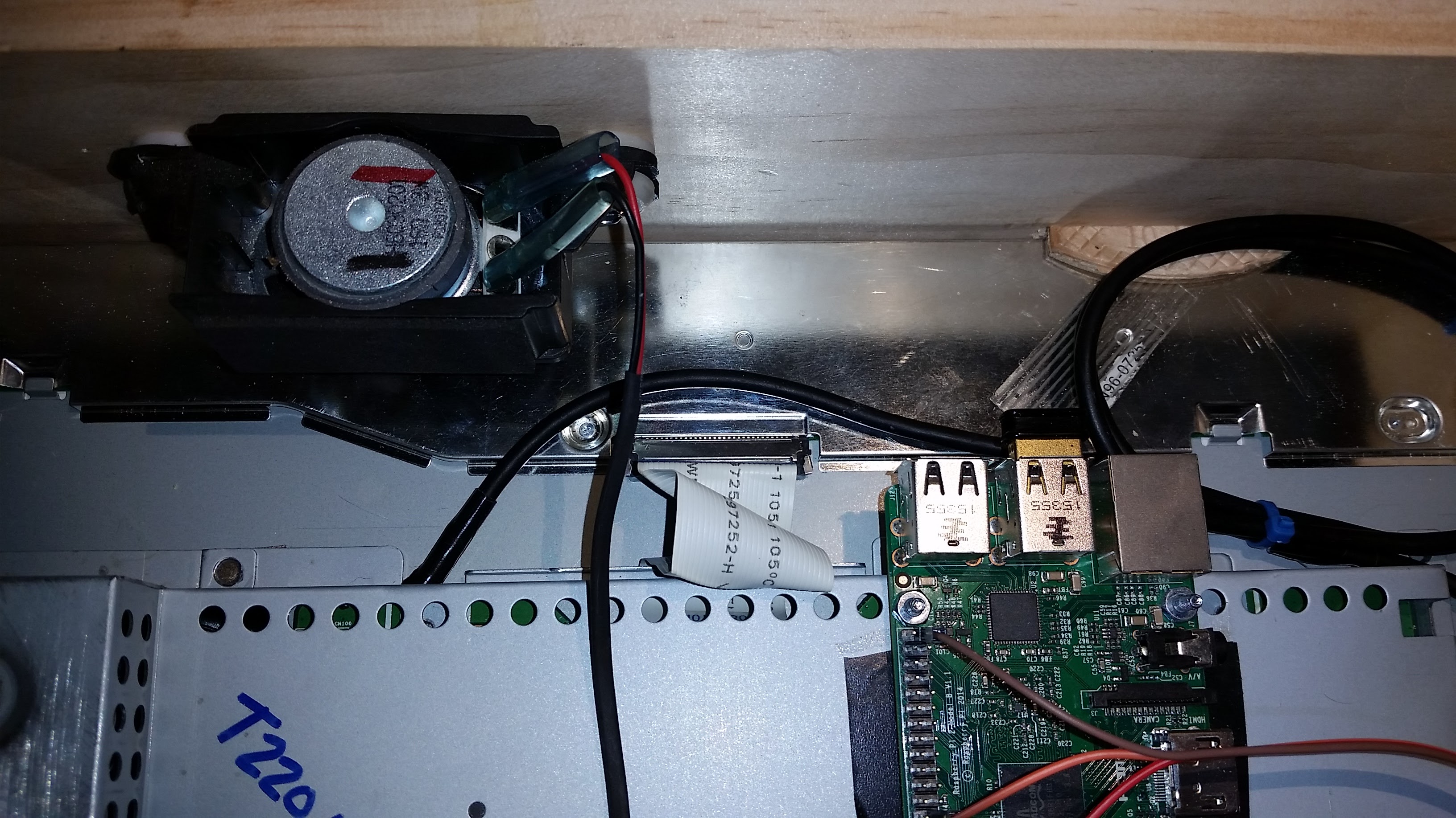
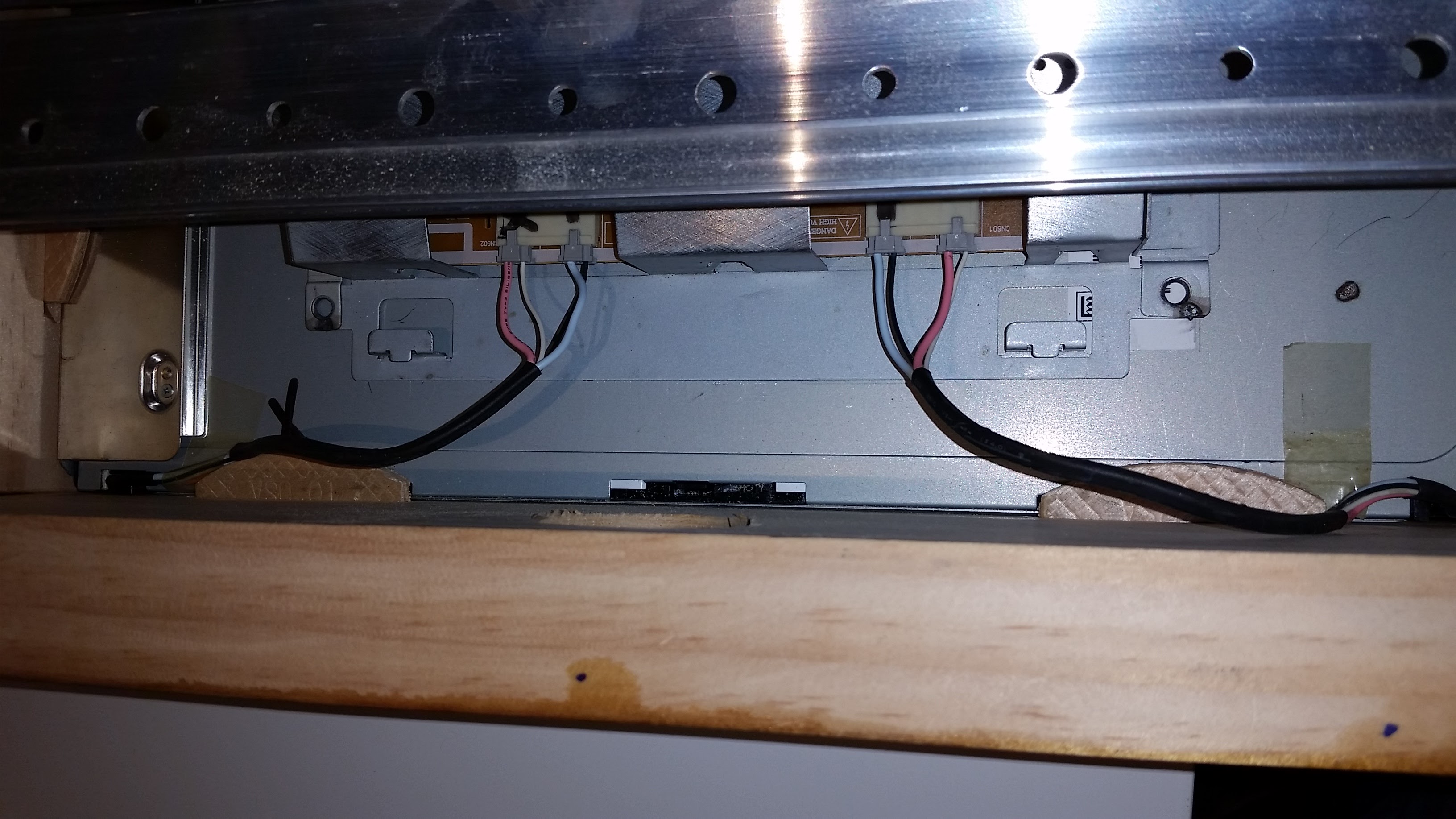
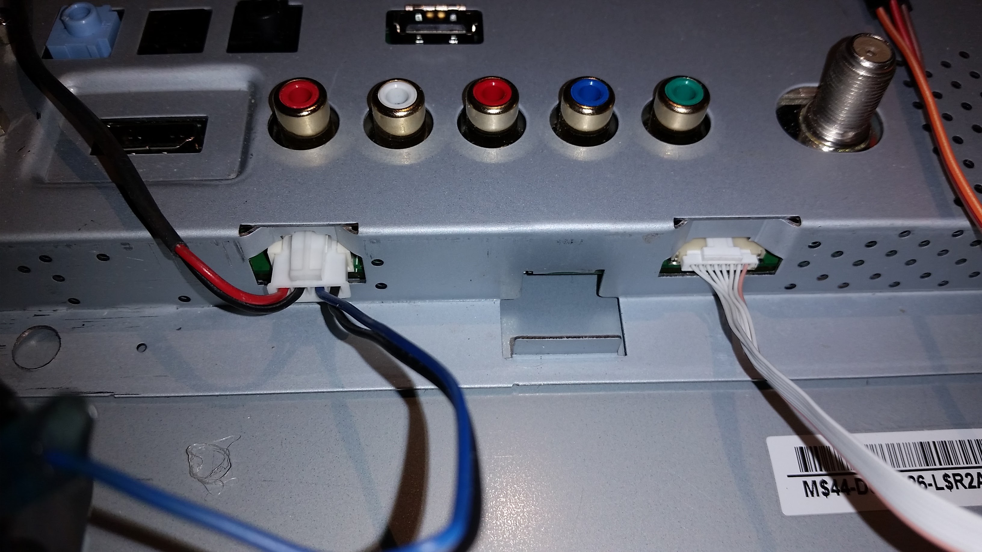
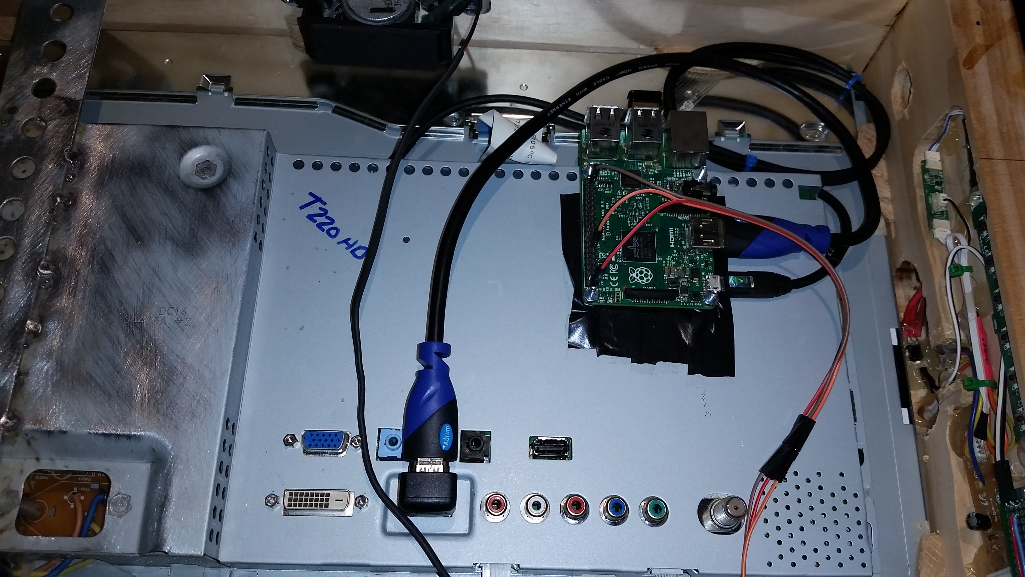
- Install WiFi adapter (and optional wireless keyboard adapter) into Raspberry PI USB slots.
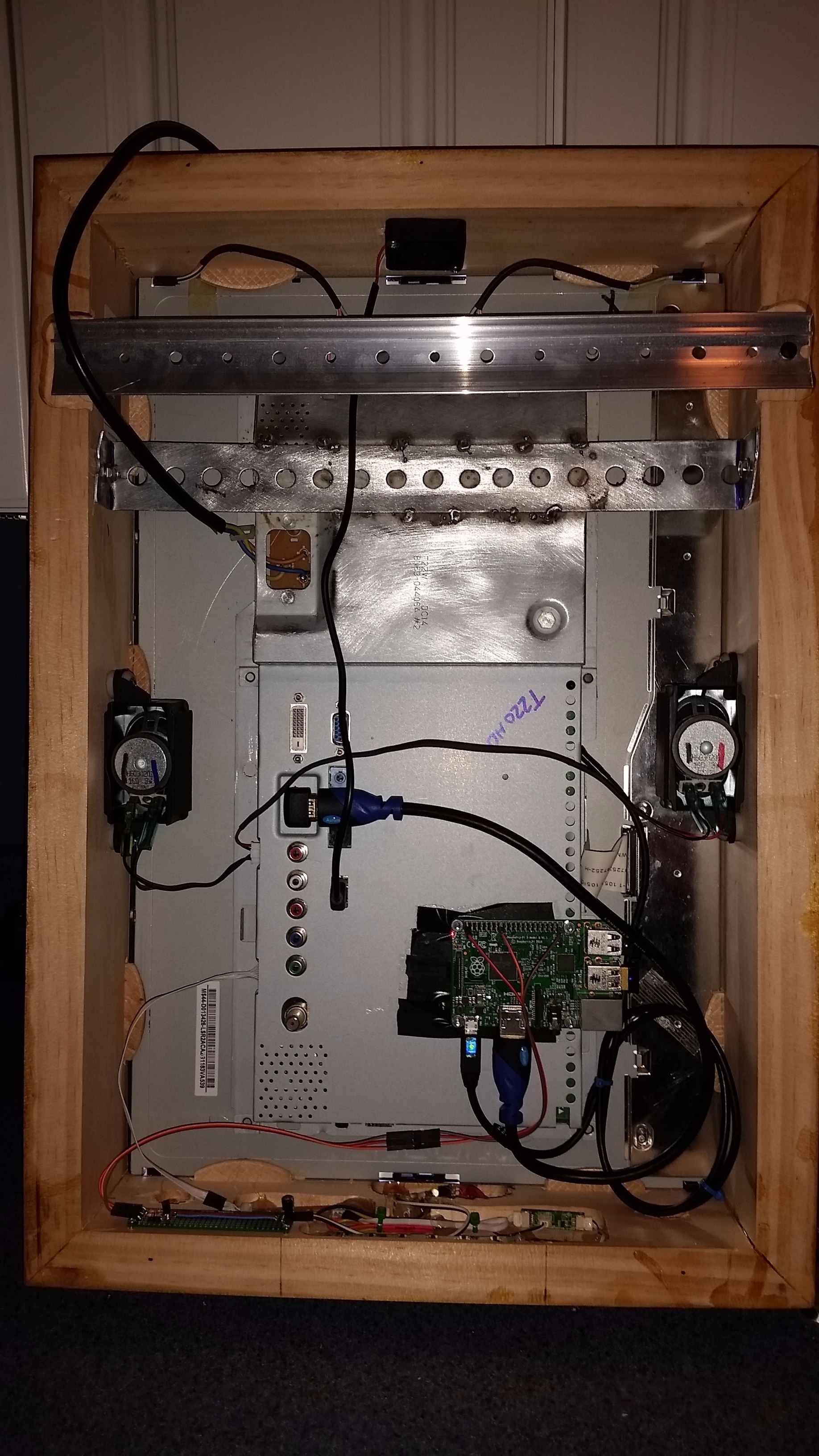
- Connect LVDS cable and the two LCD inverter power cables from LCD to tray.
- Connect factory switch harness and speakers to connectors on tray.
- Connect HDMI cable between Raspberry Pi and the HDMI port on the tray using the right angle adapter on the tray end.
- Connect micro USB power cable from Step #7 to Raspberry Pi.
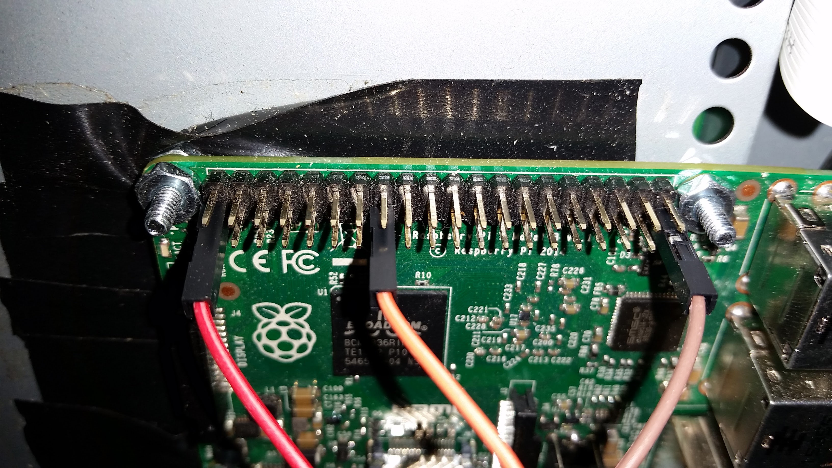
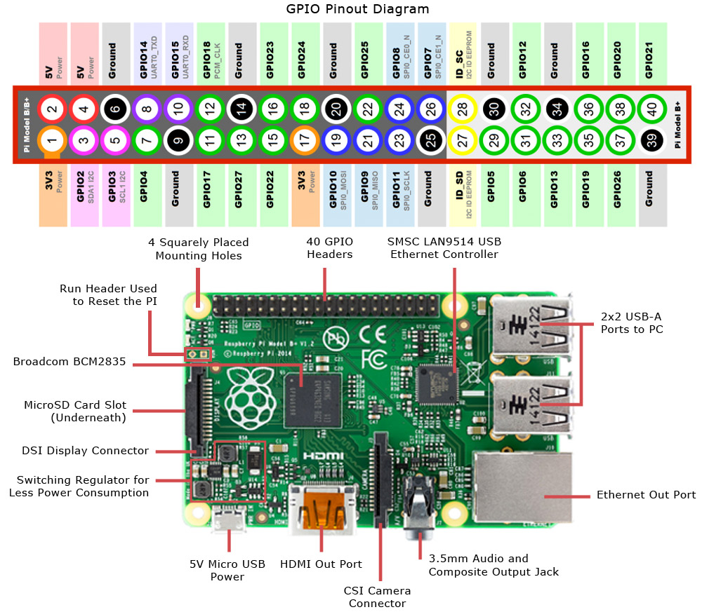
- Connect IR transmitter jumpers. Connect the 3.3v red jumper to pin #1 on the Pi, connect the orange GPIO22 signal jumper to pin #15 and the brown ground jumper to pin #39.
- Plug the 40mm fan USB cable into a USB port on the back of the tray.
Install Raspbian and Basic Setup
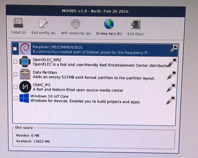
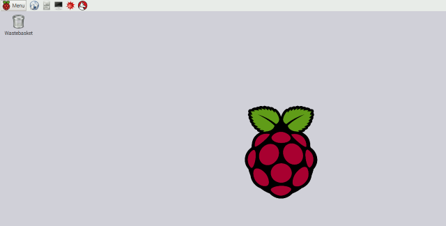
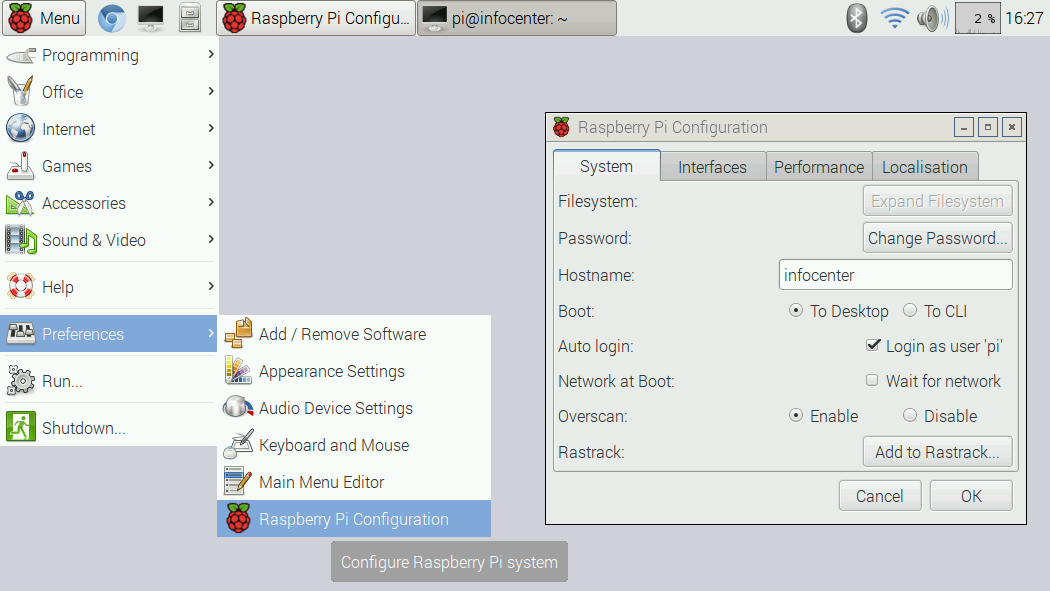
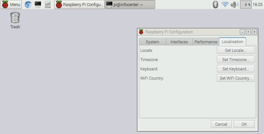
These instructions assume Raspbian GNU/Linux 8 (jessie) is installed.
- Follow the instructions on the Raspberry Pi website to prepare your Micro SD card with NOOBS which is an operating system installation manager for the Raspberry Pi and then insert the Micro SD card in the Raspberry Pi.
- Power on your infocenter and your Pi will boot to NOOBS. Follow the on screen installation instructions to install Raspbian.
- Once the install is complete you should be automatically logged in to your desktop. If not, the default user is pi and default password is raspberry. I recommend changing the default password as well as some other basic settings using the Raspberry Pi Configuration GUI under Menu > Preferences.
- Once in the Raspberry Pi Configuration GUI under the System tab, click on Expand Filesystem. This will only take a few seconds. The reason for expanding the filesystem is to make all the available space on the SD card available to use, in an effort to keep Raspbian small enough to fit on different sized SD cards it is compressed to only use about 4GB. Also, click on the Change Password button to change the default password. Give your infocenter a Hostname of your choosing, select Boot To Desktop and Auto login.
- While still in the Raspberry Pi Configuration GUI select the Localisation tab and set your Locale, Timezone and Keyboard preferences. The GUI is further documented here.
- Setup the Edimax WiFi adapter via the installation instructions on this page.
- Once WiFi is working open the terminal and update the repositories. Type the following commands.
sudo apt-get update
- Next let's update all the packages.
sudo apt-get upgrade
- Now let's update the Raspberry Pi's firmware.
sudo rpi-update
- Reboot.
sudo reboot
Install Software Packages
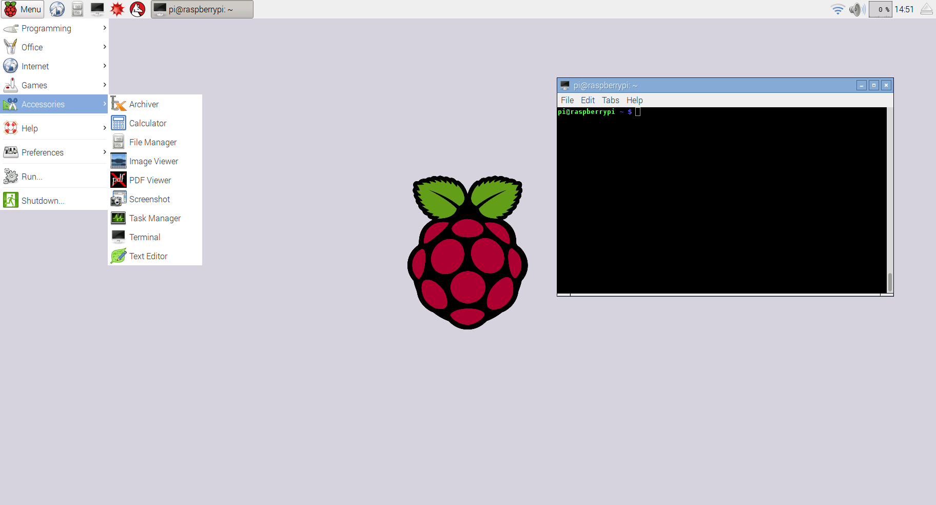
Now we will install additional packages that will be required for the infocenter. These will be configured in the next step. Open a terminal window and type the below commands.
- Install Chromium browser.
wget -qO - http://bintray.com/user/downloadSubjectPublicKey?username=bintray | sudo apt-key add -
echo "deb http://dl.bintray.com/kusti8/chromium-rpi jessie main" | sudo tee -a /etc/apt/sources.list
sudo apt-get update
sudo apt-get install chromium-browser
- Install Apache webserver.
sudo apt-get install apache2
- Install Unclutter to hide the pointer when not in use.
sudo apt-get install unclutter
- Install x11-xserver-utils
sudo apt-get install x11-xserver-utils
- Install Xdotool.
sudo apt-get install xdotool
- Install the Linux Infrared Remote Control package.
sudo apt-get install lirc
Rotate Display
I prefer the vi text editor, if you prefer nano just substitute nano for vi in the following steps.
Since the infocenter will be hung vertically instead of horizontally we will need to rotate the display. In the terminal type the commands:
sudo vi /boot/config.txt
Add the line below to the config.txt file.
add display_rotate=1 90
Chromium Setup
Chromium was installed in Step #18 now setup Chromium to autostart. In the terminal edit the file /home/pi/.config/lxsession/LXDE-pi/autostart
vi /home/pi/.config/lxsession/LXDE-pi/autostart
then add the line
@chromium-browser --start-fullscreen --disable-session-crashed-bubble --disable-infobars localhostNow we create a script to refresh Chromium
vi /home/pi/refresh.sh
Add the lines below to the file
#!/bin/bash
export DISPLAY=":0"
WID=$(xdotool search --onlyvisible --class chromium|head -1)
xdotool windowactivate ${WID}
xdotool key ctrl+F5
Make the script executable
sudo chmod +x /home/pi/refresh.shand add it to cron to run every 15 minutes
sudo crontab -eadd this line to crontab
*/15 * * * * /home/pi/refresh.sh
Setup Unclutter and Disable Screen Blanking
Unclutter and X11-xserver-utils were installed in Step #18. Unclutter will hide the pointer when not in use. In the terminal edit the file /home/pi/.config/lxsession/LXDE-pi/autostart We can also add xset commands to disable power save mode
vi /home/pi/.config/lxsession/LXDE-pi/autostart
then add the lines
@unclutter -display :0 -noevents -grab
@xset s off
@xset -dpms
@xset s noblank
To disable the screen blanking with the default LXDE, edit the file: /etc/xdg/lxsession/LXDE/autostart .
vi /etc/xdg/lxsession/LXDE/autostart
Comment out @xscreensaver command (add a # at the begging of the line)
#@xscreensaver -no-splash
To test the xset configuration you can run xset q after a reboot you should see the following output
<p>prefer blanking: no allow exposures: yes<br>timeout: 0 cycle: 600
DPMS is Disabled</p>
Setup Linux Infrared Remote Control
We installed LIRC in Step #18. Let's get it working so our Pi can send IR power on and off commands to the LCD.
sudo vi /boot/config.txt
add the following to the config.txt file
dtoverlay=lirc-rpi,gpio_out_pin=22
then edit the hardware.conf file
sudo vi /etc/lirc/hardware.conf
add the following
LIRCD_ARGS="--uinput"
LOAD_MODULES=true
DRIVER="default"
DEVICE="/dev/lirc0"
MODULES="lirc_rpi"
LIRCD_CONF=""
LIRCMD_CONF=""
Find your remote's configuration file from the list of remotes in the LIRC webpage at http://lirc.sourceforge.net/remotes/ Download the configuration file and save it as /etc/lirc/lircd.conf. In my case I used the Samsung AA59-00382A config file here http://lirc.sourceforge.net/remotes/samsung/AA59-00382A
cp AA59-00382A.lircd.conf /etc/lirc/lircd.conf
Then you should be able to test LIRC with this power on/off command
/usr/bin/irsend SEND_ONCE Samsung_AA59-00382A KEY_POWER
If you like you can set up a schedule to power on and off your LCD using cron. Edit crontab and add a schedule of your choice. In my example the infocenter powers on everyday at 8:00am, then powers off at 10:00am on days 1-5 (weekdays), powers back on at 3:00pm (15:00) on days 1-5 (weekdays) and then powers off every day at 1:00am.
sudo crontab -e
0 8 * * * /usr/bin/irsend SEND_ONCE Samsung_AA59-00382A KEY_POWER >/dev/null 2>&1
0 10 * * 1-5 /usr/bin/irsend SEND_ONCE Samsung_AA59-00382A KEY_POWER >/dev/null 2>&1
0 15 * * 1-5 /usr/bin/irsend SEND_ONCE Samsung_AA59-00382A KEY_POWER >/dev/null 2>&1
0 1 * * * /usr/bin/irsend SEND_ONCE Samsung_AA59-00382A KEY_POWER >/dev/null 2>&1
Create Your Webpage

At this point you should have a functioning infocenter that displays the default Apache "It works!" web page. Now we need to create your custom web page. You can design this as you wish making it as simple or complex as you like. I have included two sample webpages, one is the page I am using with the URLs removed and the other is a calendar only example. With either one you will need to enter your own URLs. Then rename the file to index.html and place in /var/www/html/
Since there are infinite ways your could design this page and everyone's use case will be different I'm not going to detail the entire html file here. There are plenty of great Instructables and tutorials on the web detailing how to create web pages and even more on how to embed whatever content you like.
Hang and Enjoy!
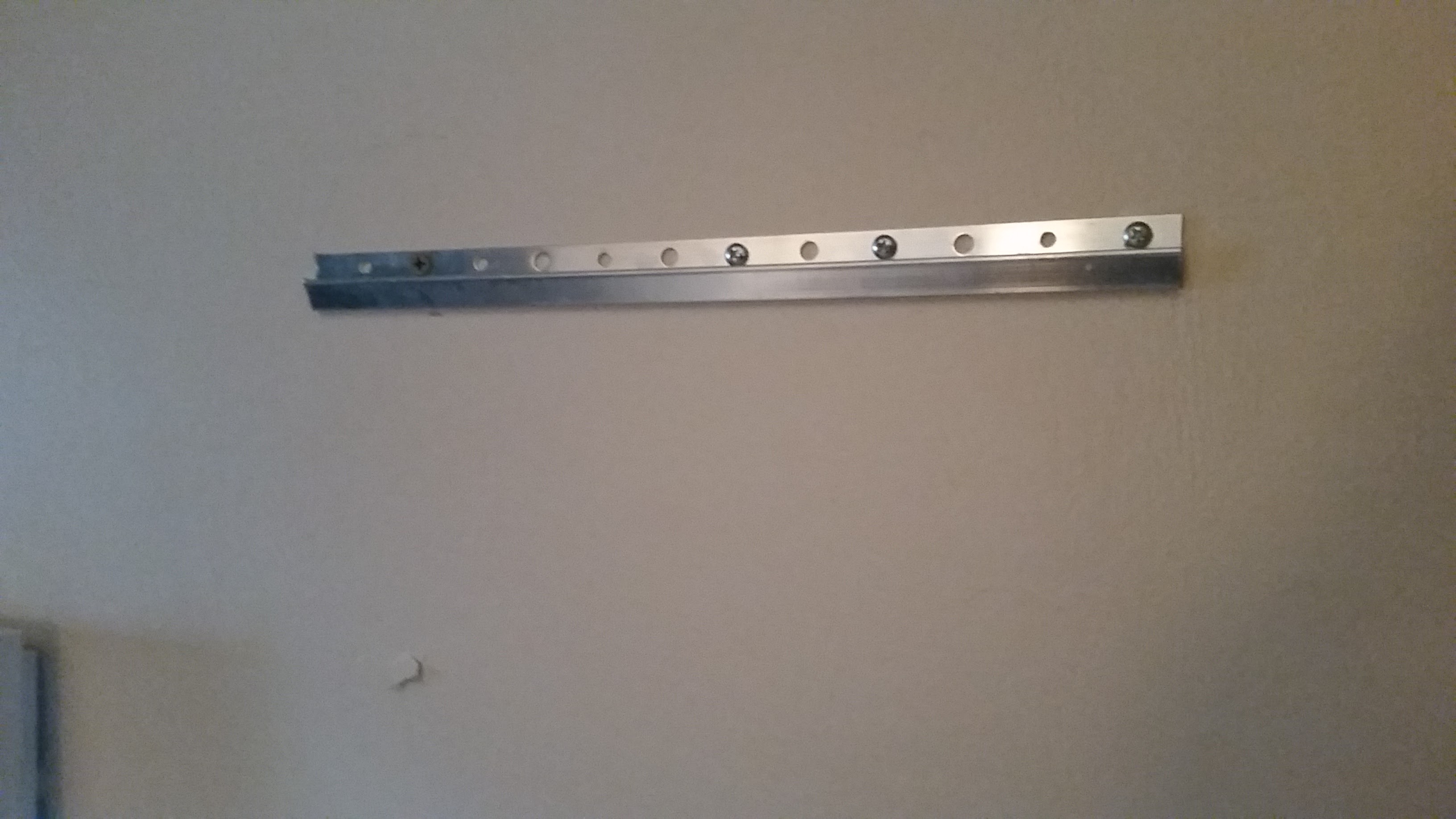
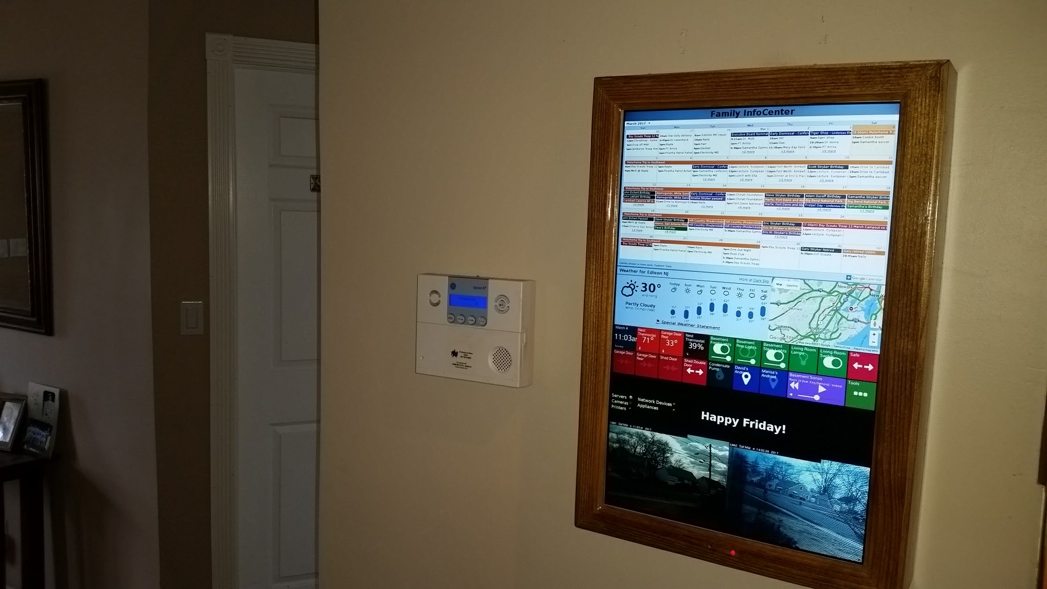
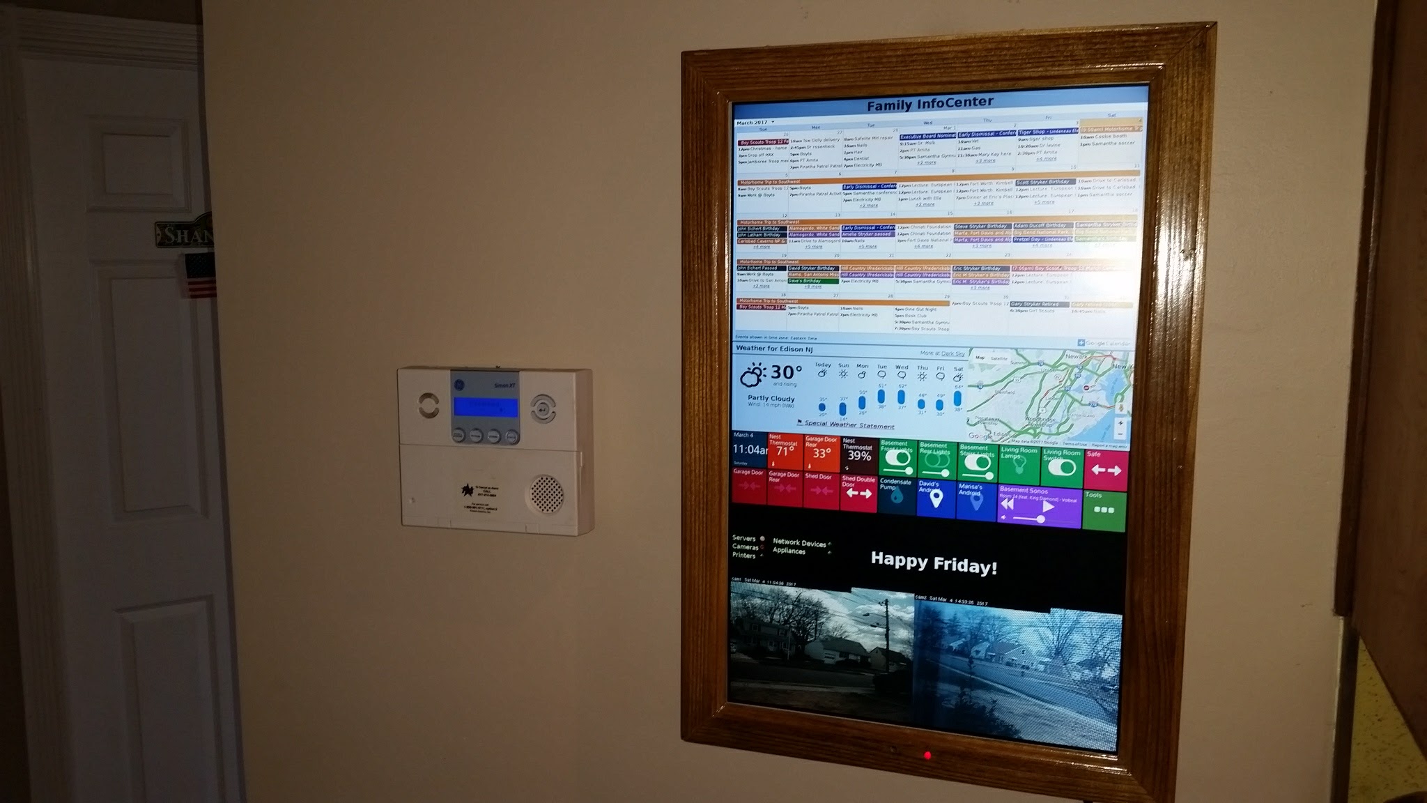
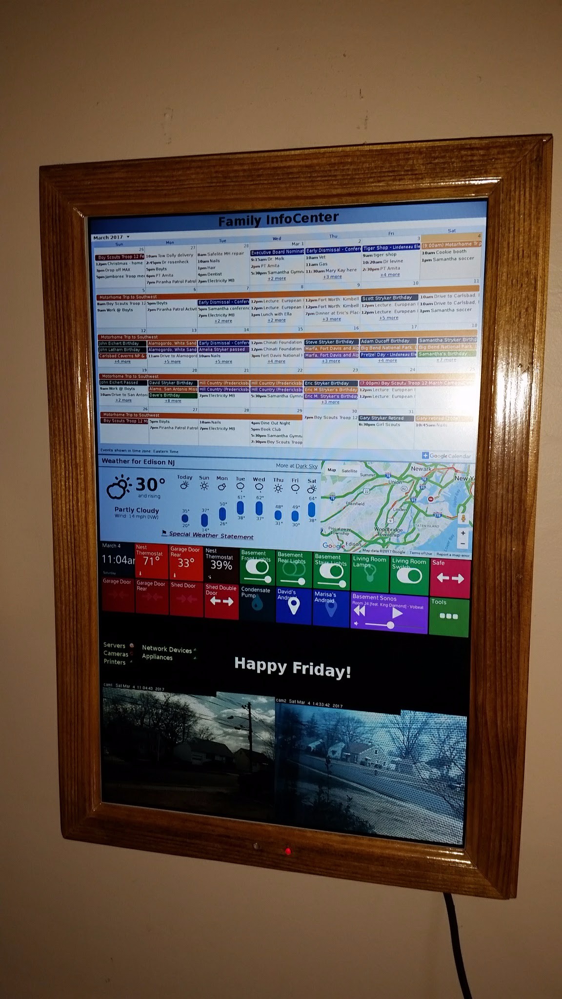
Mount the other half of your french cleat on your wall, making sure it is level, and hang your infocenter. Plug it in and enjoy!