Digital Display for ESP8266
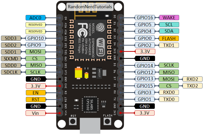
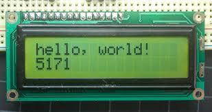
In this project you will learn how to connect Arduino's digital display to your ESP8266 board and how to display IP addresses on the display.
Supplies
Things you will need:
1. An ESP8266 board
2. Arduino's digital display
3. Jumper wires (around 20)
4. Power supply, the display needs 5v and the board takes 3.3v
5. A UART cord and USB cord
6. (Optional) Potentiometer (used to change the contrast on the board)
7. (Software) USB to UART Bridge Driver (available here: https://www.silabs.com/products/development-tools/software/usb-to-uart-bridge-vcp-drivers)
Wire the Board
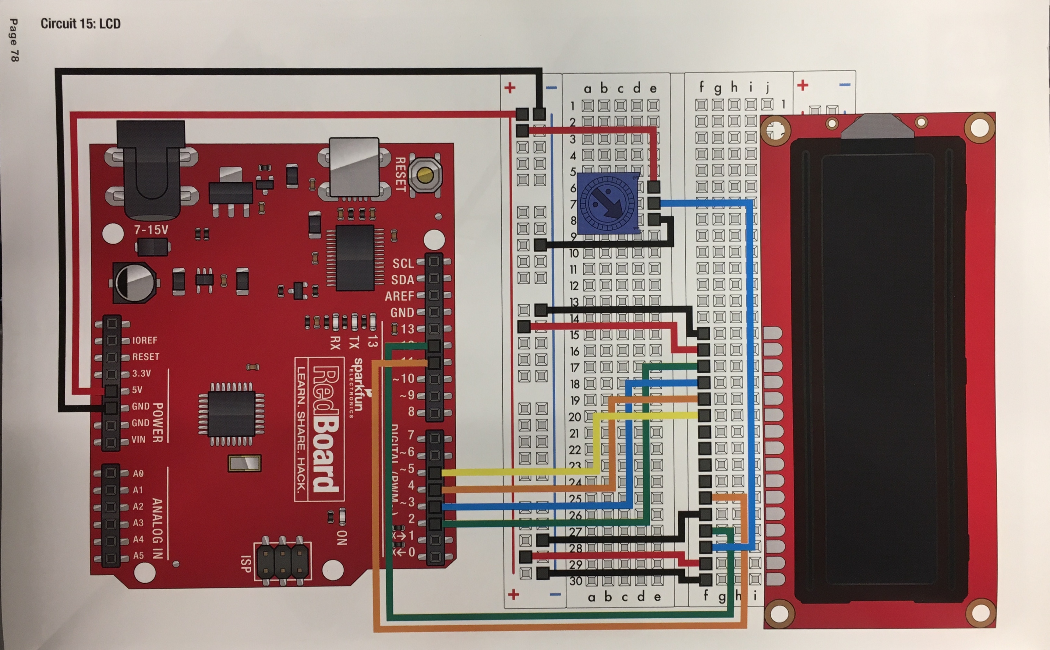
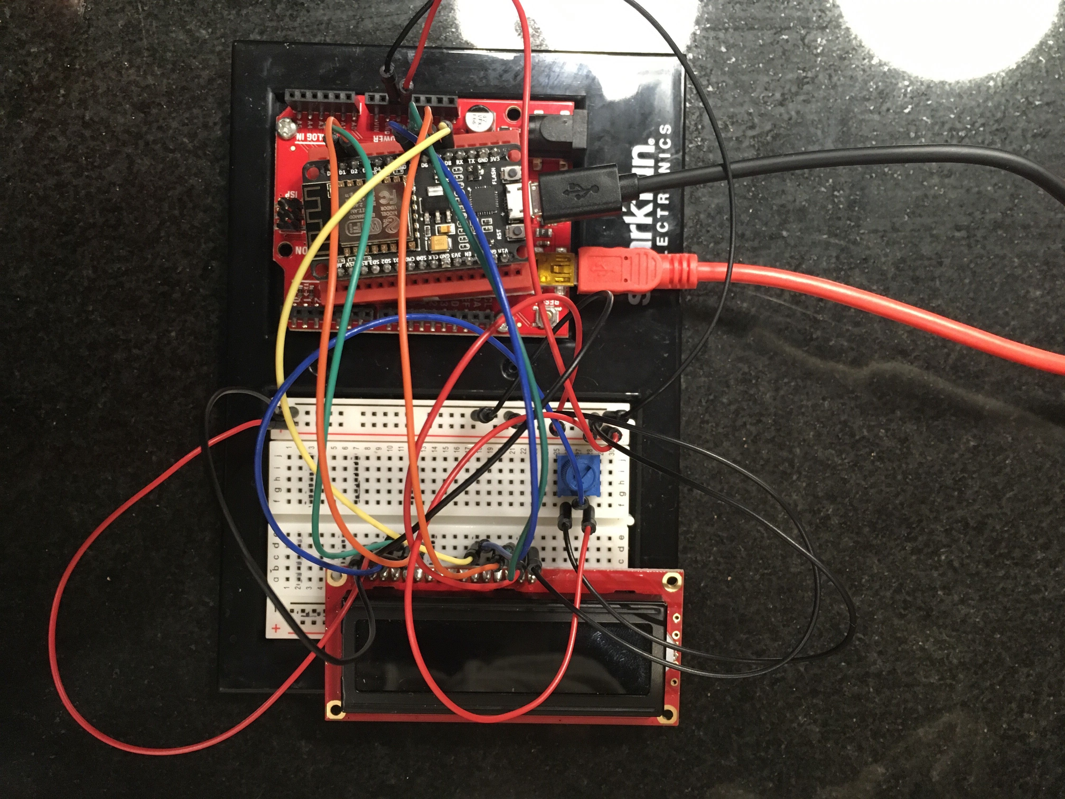
The first step in the process is wiring the board. For this you can follow the wiring schematics provided in the spark labs arduino kit. Just use the ESP8266's GPIO pins instead of the Arduino's pins. If you do have an Arduino on hand then use it's 5 volt and ground pin to power the display. If you don't then just make sure to use a 5 volt power supply to power the display. Don't use the ESP8266 to power the display, it will not have enough volts.
Program the Board
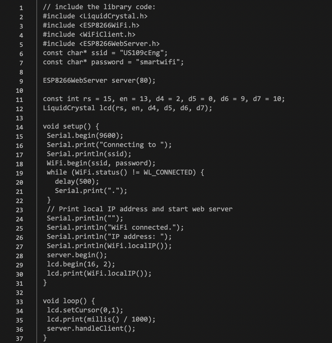
The next step is to write code for the board. Here I have provided code written by my friend (all credit goes to Steven Mu for this). What he's done is included four libraries at the top - the first being to run commands for the lcd screen and the other three for the ESP's wifi commands. He also creates variables for the wifi he wants to connect to and its password. He also defines variables for the various pins on the lcd screen. Next he basically connects to the wifi, asks for its IP address, then prints it out to the screen.
Testing
If everything goes smoothly the IP address should print out to the lcd screen. If not, check to make sure your connections are well wired and your pins are correct.