Digital Dice: Random Number Generator 1-6
by krrudolph167 in Circuits > Arduino
2002 Views, 4 Favorites, 0 Comments
Digital Dice: Random Number Generator 1-6
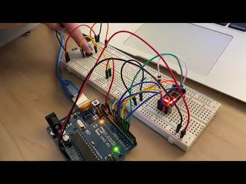
Are you a classroom teacher? Do your students LOVE to play math and problem solving games? Does the sound of dice rolling on the tables make you want to scream?! Then this project is for you!
This project uses an Arduino UNO as a random number generator. It generates numbers 1-6, so you never need to hear a dice rolling again! By the simple click of a button, the number will appear and students can play games all day long. A pushbutton is used to generate the random number on a 7 segment display.
A beginner (such as myself) can complete this project.
Supplies
(1) Arduino UNO
(1) Breadboard
(14) Jumper Wires
(1) Push Button
(1) 7 Segment Display
(2) Resistors
Connecting the Arduino UNO
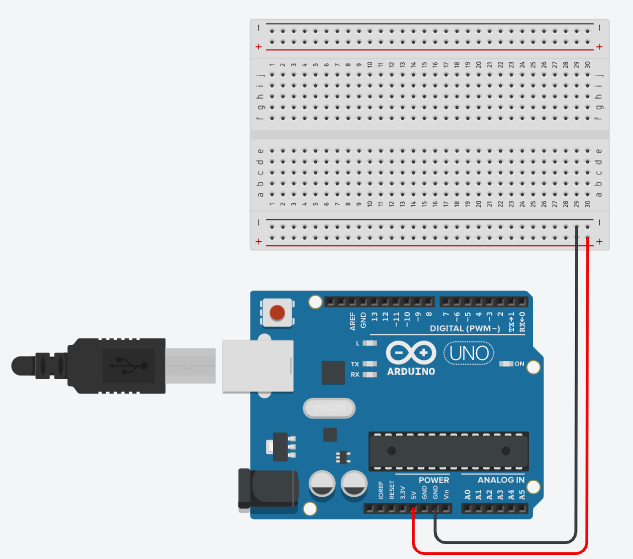
Here are the steps you will need to connect and wire your Arduino UNO for the random Dice Generator. Follow the diagram created on TinkerCad.
1. Connect the breadboard to the Arduino by placing a wire from 5V to +, and GRD to -.
Connecting the Pushbutton to the Breadboard
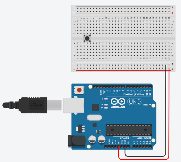
2. Place the pushbutton onto the breadboard, splitting between the two sides of the breadboard.
Connecting One Side of the Breadboard to the Other
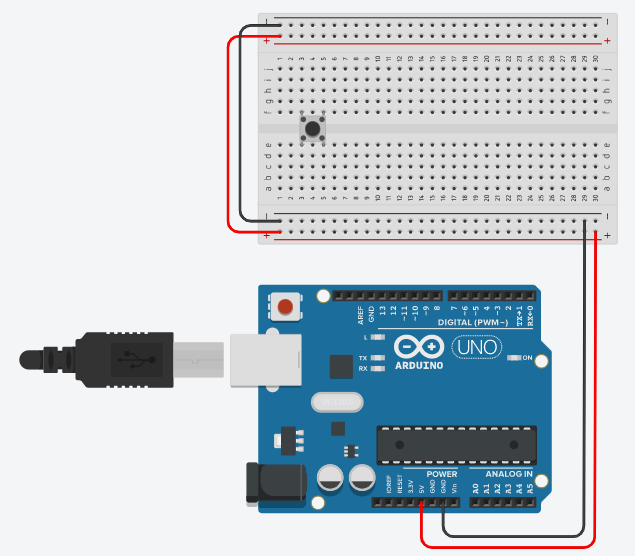
3. Connect one side of the breadboard to the other by adding a wire from + to + and - to -.
Connecting the Pushbutton to the Arduino
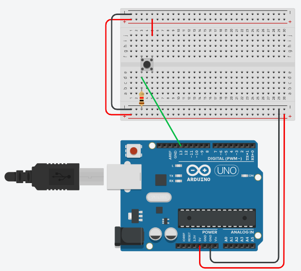
4. Add a resistor from the pushbutton to the -. Add a wire from the pushbutton to the +. Connect the pushbutton to 13.
Placing the 7 Segment Display
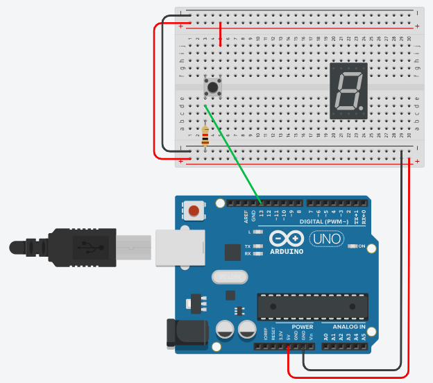
5. Place the 7 Segment Display on the breadboard.
Connect the Display to the Arduino
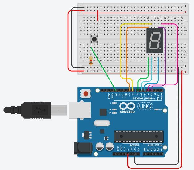
6. Connect wires from the display's columns to the Arduino pins, 3-9.
-pin 3 connects to column 4 on top, controlling the top segment of the display.
-pin 4 connects to column 5 on top, controlling the top right segment of the display.
-pin 5 connects to column 4 on bottom, controlling the bottom right segment of the display.
-pin 6 connects to column 2 on bottom, controlling the bottom segment of the display.
-pin 7 connects to column 1 on bottom, controlling the bottom left segment of the display.
-pin 8 connects to column 2 on top, controlling the top left segment of the display.
-pin 9 connects to column 1 on top, controlling the middle segment of the display.
Connect Both Sides of the Display to the Breadboard
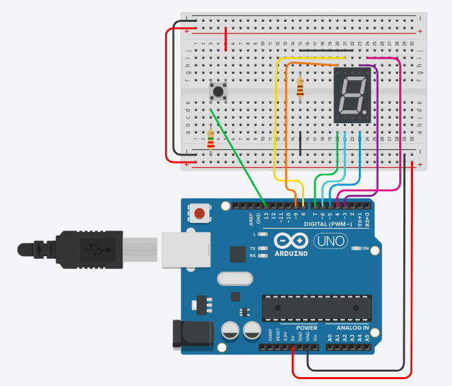
7. Add a wire from the top middle column of the display, to another row on the breadboard. Connect this row to the other side of the breadboard with a resistor, and add a wire connecting the resistor's row to -.
Here Comes the Code!

The first component of the code is to define the variable. Check it out below, or find the entire code, here.
int Dice = 0;
Here Comes the Code: Setup

The next component of the code is the setup. Check it out below, or find the entire code, here.
void setup() {
pinMode(13, INPUT); //This is indicating the input from the button being pressed
pinMode(3, OUTPUT); //This is indicating the output from the top line of the display.
pinMode(4, OUTPUT); //This is indicating the output from the top right line of the display.
pinMode(5, OUTPUT); //This is indicating the output from the bottom right line of the display.
pinMode(6, OUTPUT); //This is indicating the output from the bottom line of the display.
pinMode(7, OUTPUT); //This is indicating the output from the bottom left line of the display.
pinMode(8, OUTPUT); //This is indicating the output from the top left line of the display.
pinMode(9, OUTPUT); //This is indicating the output from the middle line of the display.
}
Here Comes the Code: Loop
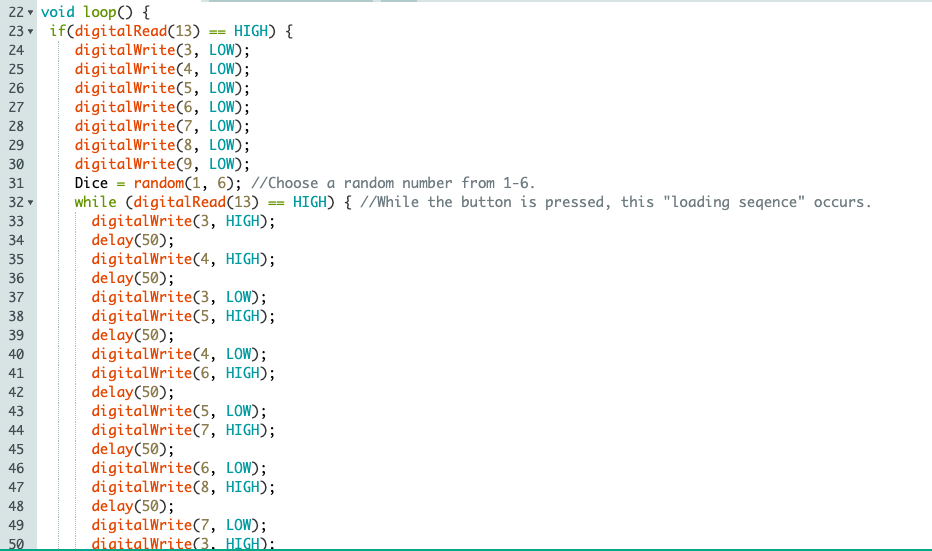
The next step in the code is for the loop. Check it out below, or find the entire code, here. There are descriptors next to the sections of code to describe their purpose.
void loop() {
if(digitalRead(13) == HIGH) {
digitalWrite(3, LOW);
digitalWrite(4, LOW);
digitalWrite(5, LOW);
digitalWrite(6, LOW);
digitalWrite(7, LOW);
digitalWrite(8, LOW);
digitalWrite(9, LOW);
Dice = random(1, 6); //Choose a random number from 1-6.
while (digitalRead(13) == HIGH) { //While the button is pressed, this "loading sequence" occurs. digitalWrite(3, HIGH);
delay(50);
digitalWrite(4, HIGH);
delay(50);
digitalWrite(3, LOW);
digitalWrite(5, HIGH);
delay(50);
digitalWrite(4, LOW);
digitalWrite(6, HIGH);
delay(50);
digitalWrite(5, LOW);
digitalWrite(7, HIGH);
delay(50);
digitalWrite(6, LOW);
digitalWrite(8, HIGH);
delay(50);
digitalWrite(7, LOW);
digitalWrite(3, HIGH);
delay(50);
digitalWrite(8, LOW);
digitalWrite(4, HIGH);
delay(50);
digitalWrite(3, LOW);
digitalWrite(5, HIGH);
delay(50);
digitalWrite(4, LOW);
digitalWrite(6, HIGH);
delay(50);
digitalWrite(5, LOW);
digitalWrite(7, HIGH);
delay(50);
digitalWrite(6, LOW);
digitalWrite(8, HIGH);
delay(50);
digitalWrite(7, LOW);
delay(50);
digitalWrite(8, LOW);
delay(100); }
if(digitalRead(13) == LOW) { //When the button is not pressed, the chosen number will appear on the display.
if(Dice == 1) { //If the number chosen is 1.
digitalWrite(3, LOW);
digitalWrite(4, HIGH);
digitalWrite(5, HIGH);
digitalWrite(6, LOW);
digitalWrite(7, LOW);
digitalWrite(8, LOW);
digitalWrite(9, LOW); }
if(Dice == 2) { //If the number chosen is 2.
digitalWrite(3, HIGH);
digitalWrite(4, HIGH);
digitalWrite(5, LOW);
digitalWrite(6, HIGH);
digitalWrite(7, HIGH);
digitalWrite(8, LOW);
digitalWrite(9, HIGH); }
if(Dice == 3) { //If the number chosen is 3.
digitalWrite(3, HIGH);
digitalWrite(4, HIGH);
digitalWrite(5, HIGH);
digitalWrite(6, HIGH);
digitalWrite(7, LOW);
digitalWrite(8, LOW);
digitalWrite(9, HIGH); }
if(Dice == 4) { //If the number chosen is 4.
digitalWrite(3, LOW);
digitalWrite(4, HIGH);
digitalWrite(5, HIGH);
digitalWrite(6, LOW);
digitalWrite(7, LOW);
digitalWrite(8, HIGH);
digitalWrite(9, HIGH); }
if(Dice == 5) { //If the number chosen is 5.
digitalWrite(3, HIGH);
digitalWrite(4, LOW);
digitalWrite(5, HIGH);
digitalWrite(6, HIGH);
digitalWrite(7, LOW);
digitalWrite(8, HIGH);
digitalWrite(9, HIGH); }
if(Dice == 6) { //If the number chosen is 6.
digitalWrite(3, HIGH);
digitalWrite(4, LOW);
digitalWrite(5, HIGH);
digitalWrite(6, HIGH);
digitalWrite(7, HIGH);
digitalWrite(8, HIGH);
digitalWrite(9, HIGH); }
}
}
}
You Have a Digital Dice!
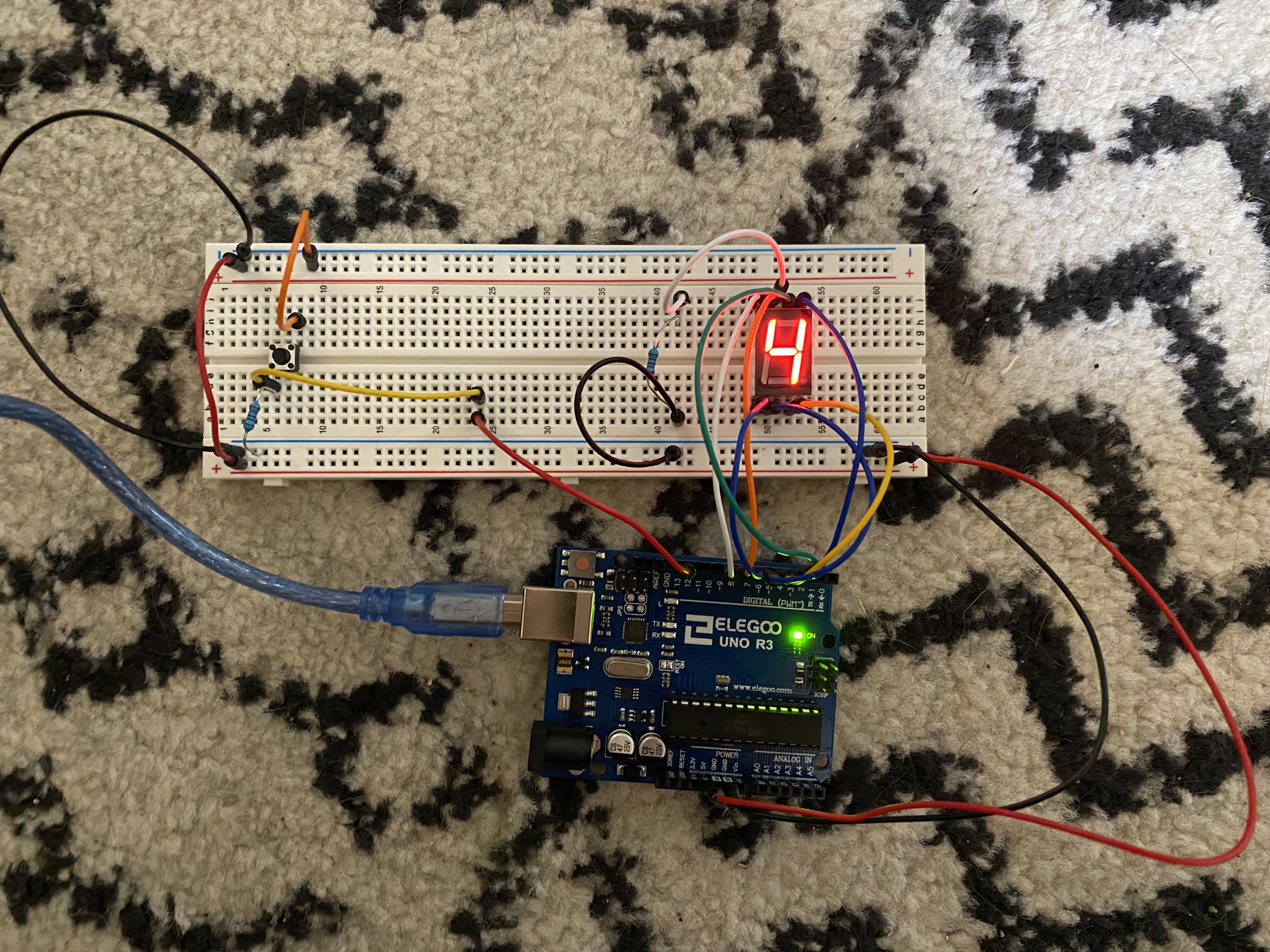
You did it! You never have to hear rolling dice in a classroom again!
Inspiration came from:
Instructables, SW9761. (2020, May 7). LED Random Number Generator. Retrieved from https://www.instructables.com/id/LED-Random-Number-Generator/