Digital Dice
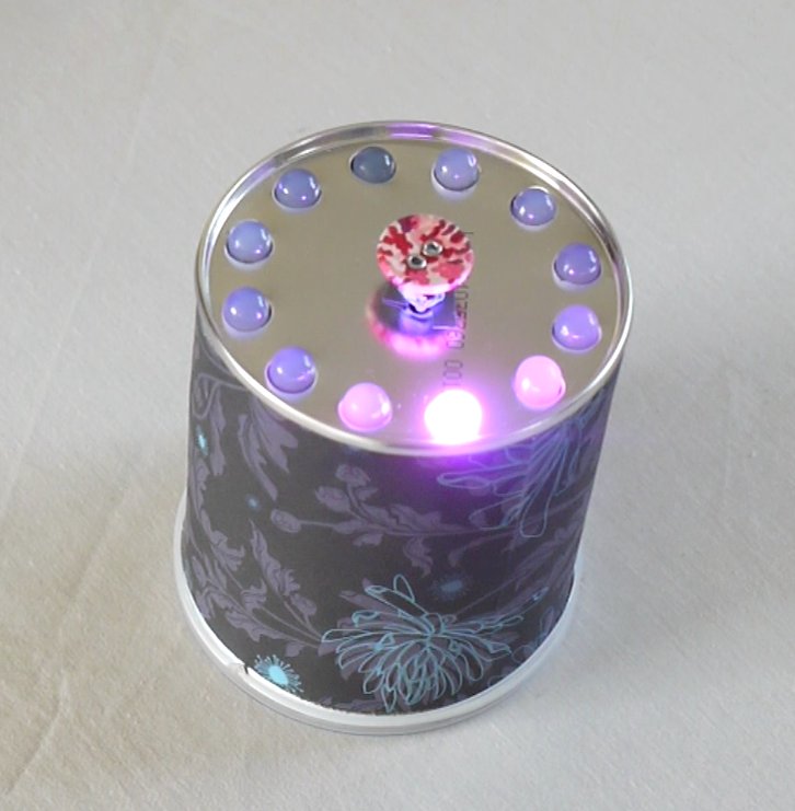
This instructable shows you how to make a Digital Dice - just press the button on top, there will be a quick animation, and one of the 12 lights will light up at random!
What You Need
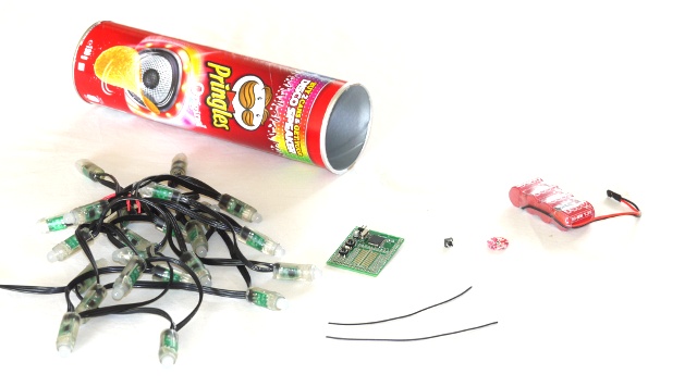
A clean and empty Pringles Can
An Espruino Board (http://www.espruino.com)
A battery
A switch, and two wires for it
A string of 12 WS2811 RGB LED Lights
(Not shown) Wrapping paper, tape, and double-sided tape
An Espruino Board (http://www.espruino.com)
A battery
A switch, and two wires for it
A string of 12 WS2811 RGB LED Lights
(Not shown) Wrapping paper, tape, and double-sided tape
Cutting the Tube
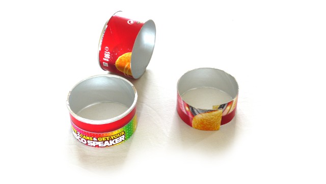
Measure 4cm from each end of the pringles can, and use a craft knife to cut it as straight as possible.
Also cut another ring from the middle of the can, around 3cm wide. Cut across it as well - this will help to hold the LED lights in place.
Also cut another ring from the middle of the can, around 3cm wide. Cut across it as well - this will help to hold the LED lights in place.
Drilling Holes
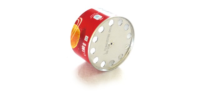
Then, cut 12 equally spaced (8mm) holes in the tin end of the can, about 2mm from the edge. You'll also need a hole in the middle for your switch. We marked ours by hand with a marker pen until they looked about right, and then drilled them out.
Put the two ends of the can back together, and tape them together on the inside.
Finally apply double-sided sticky tape around the outside of the can, and then use some patterned paper (like wrapping paper) to cover up the pringles text.
Put the two ends of the can back together, and tape them together on the inside.
Finally apply double-sided sticky tape around the outside of the can, and then use some patterned paper (like wrapping paper) to cover up the pringles text.
Adding the LEDs
Look carefully at the two ends of your strip of lights. Through the clear plastic you should be able to see markings on the PCB where the wires connect. One set should clearly say '5V, DI, GND', the other might say 'DO' in the middle (or you might not be able to make anything out). Make sure you mark the end of the lights marked with '5V, DI, GND' - you don't care about the other end at all, so just make sure it stays out of the way.
Then push each one of the 12 LEDs into their holes (in order). You can use blu-tack or double-sided tape to hold them in place.
Put the third ring of the Pringles can inside the LEDs to hold them in place - add some tape to it to help hold it in position.
Then push each one of the 12 LEDs into their holes (in order). You can use blu-tack or double-sided tape to hold them in place.
Put the third ring of the Pringles can inside the LEDs to hold them in place - add some tape to it to help hold it in position.
Soldering Up
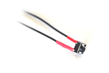
Now, connect the two wires to your switch. We've used some head-shrink sleeving to stop the contacts shorting out, but you could use tape again. Having the contacts short won't damage anything, but it'll make Espruino think the button has been pressed when it hasn't!
Solder the wires to Espruino. For the connections, see Here:
Connect the other end to 'A1' on Espruino (any data pin would do for this)
Connect one end of the switch to a pad marked 3.3V (it should be right next to A1)
On the lights, take the end that was marked '5V, DI, GND', and separate out the 3 sets of wires that correspond to each marking.
Connect '5V' to 'VBAT' on Espruino
Connect 'GND' to 'GND' on Espruino
Connect 'DI' to 'B5' on Espruino (for this one, you need a pin that is marked SPI#_MOSI)
You're done - you can now connect the battery!
Fitting Together
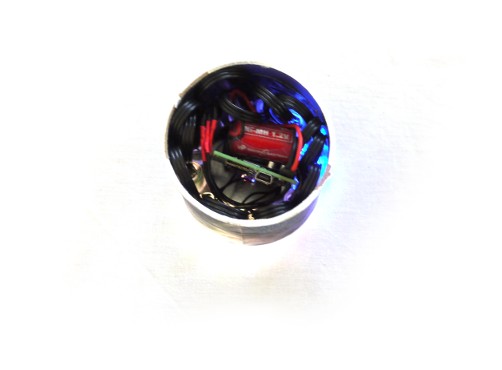
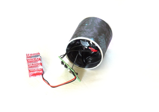
And now, you can tuck everything inside. The Espruino board and battery should fit snugly in the middle of the LED lights.
Make sure the USB connector faces outwards so that you can connect to it with your PC.
Make sure the USB connector faces outwards so that you can connect to it with your PC.
Software!

Now, for the software! Connect your computer as described in the Espruino Quick Start. You can follow the examples in the LED Lights Tutorial to play with the lights - remember to use 'B5' as the SPI pin though.
Just copy and paste the code from one of the two files into the terminal window - or copy it from the bottom of the website here
You've now got a working Digital Dice! Type 'save()' and everything will be saved to flash, so the next time you power on your Digital Dice it'll auto-load the Digital Dice software!
If you change the software and add more functionality, let us know!