Digital Clock Using Tinkercad
by veerapec2012 in Circuits > Arduino
16975 Views, 4 Favorites, 0 Comments
Digital Clock Using Tinkercad
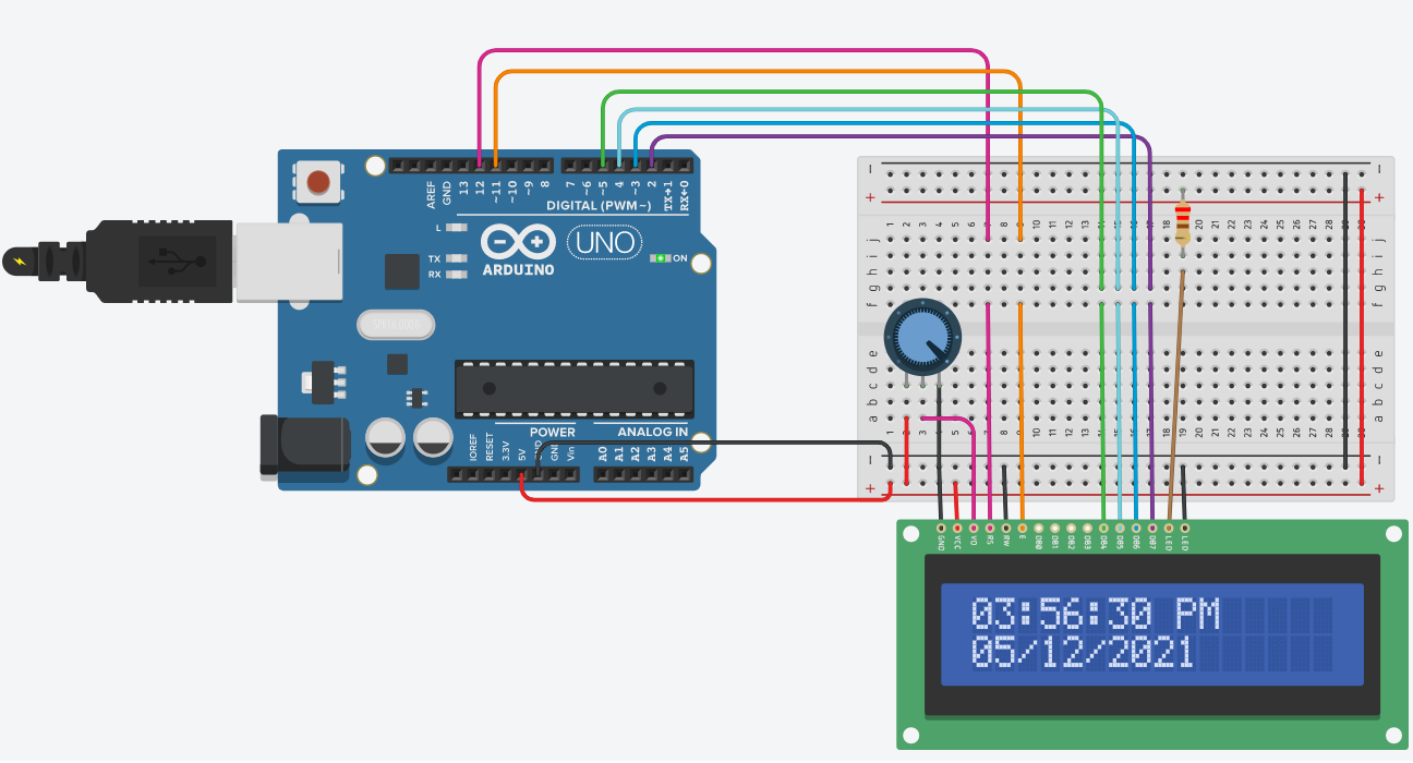
Tinkercad is one of the best software tools for 3D modeling and simulating the circuits. I have created a Digital Clock circuit using Tinkercad. I have used Arduino Uno R3, LCD 16x2, Potentiometer and a 220-ohm resistor for making the circuit. I used a simple sketch, which is attached and explained in this instructable. I ran the sketch and found my digital clock working fine after setting the present time and date using serial monitor.
Supplies
Arduino Uno R3
LCD 16x2
Potentiometer
and a 220-ohm resistor
Drag and Drop the Components to the Workspace
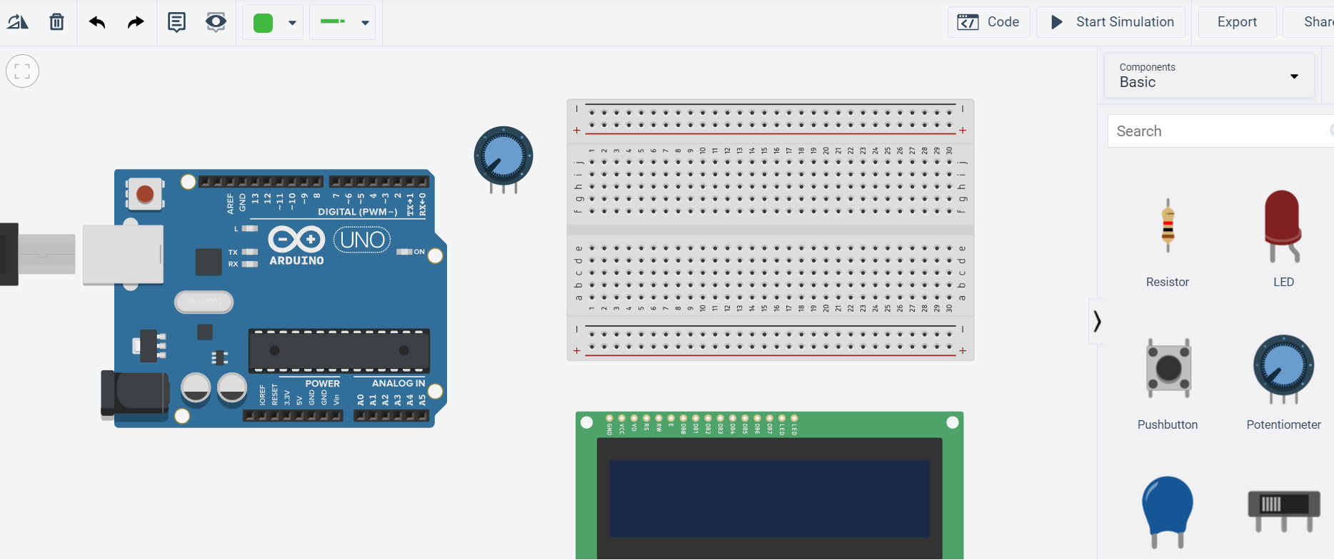
Create a circuit project in Tinkercad after login using your account details. Drag and drop the components mentioned in the supplies to the workspace. You can also use the search bar for finding the required components, which are available next to the workspace in the right hand side.
Circuit Diagram and Connection Procedure
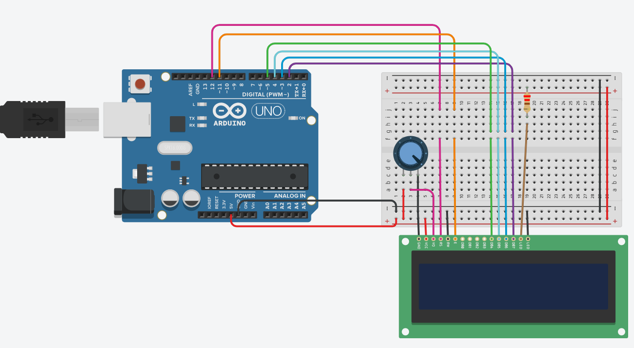
1. Connect the 5V pin from Arduino Uno to the positive rails of the breadboard
2. Connect the ground (GND) pin from Arduino Uno to the negative rails of the breadboard
3. Place the potentiometer on the breadboard, and connect terminals 1 and 2 of the potentiometer to the positive and negative rails of the breadboard, respectively.
4. Connect the ground (GND) pin of the LCD to the negative rail of the breadboard.
5. Connect the power (VCC) pin of the LCD to the positive rail of the breadboard.
6. Connect the contrast (V0) pin of the LCD to the wiper pin of the potentiometer through the breadboard.
7. Connect the Register Select (RS) pin of the LCD to the digital pin 12 of the Arduino through the breadboard.
8. Connect the Read/Write (RW) pin of the LCD to the negative rail of the breadboard.
9. Connect the Enable (E) pin of the LCD to the digital pin 11 of the Arduino through the breadboard.
10. Data pins DB0 to DB3 of the LCD are not connected to anything because we are using 4-wire mode (only four pins are connected to the Arduino).
11. Data pins DB4 to DB7 of the LCD are connected to the Arduino digital pins 5 to 2, respectively.
12. LED Anode of the LCD is connected to the positive rail of the breadboard through 220 ohm resistor, and LED Cathode of the LCD is connected to the negative rail of the breadboard.
Programming the Digital Clock
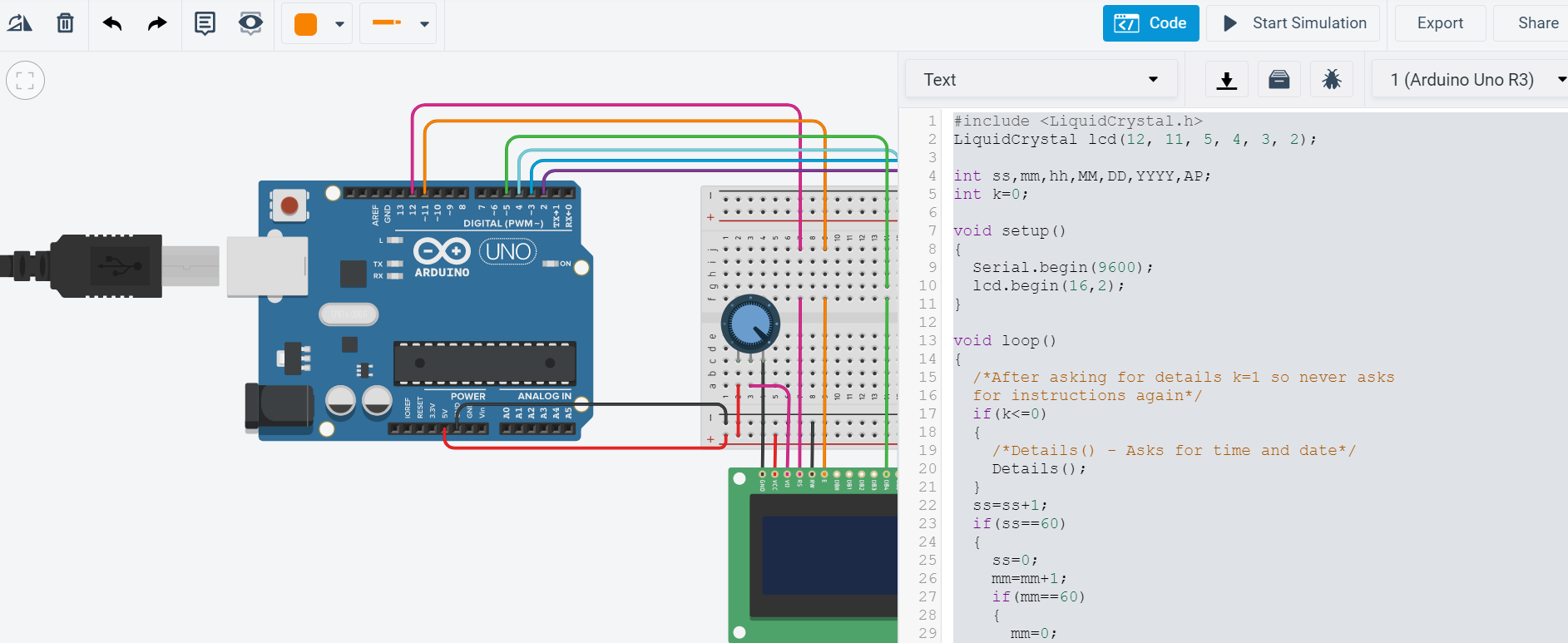
Click on the "Code" option available in the Tinkercad and write the following program in it.
#include LiquidCrystal lcd(12, 11, 5, 4, 3, 2);
int ss,mm,hh,MM,DD,YYYY,AP;
int k=0;
void setup()
{
Serial.begin(9600);
lcd.begin(16,2);
}
void loop()
{
/*After asking for details k=1 so never asks for instructions again*/
if(k<=0)
{
/*Details() - Asks for time and date*/
Details();
}
ss=ss+1;
if(ss==60)
{
ss=0;
mm=mm+1;
if(mm==60)
{
mm=0;
hh=hh+1;
if(hh==12)
{
AP=AP+1;
printTime2();
/*Day only advances when going from PM to AM*/
if(AP%2==0)
{
DD=DD+1;
}
// assumes that all months have 28 days
if(DD==28)
{
DD=1;
MM=MM+1;
if(MM==13)
{
MM=1;
YYYY=YYYY+1;
}
}
}
if(hh==13)
{
hh=1;
}
}
}
/*printTime2 - adds one second and displays time on LCD display*/
printTime2();
}
void line()
{
Serial.println("");
}
void Details()
{
Serial.println("Enter current hour:");
while(Serial.available()==0);
hh=Serial.parseInt();
/*line() - inserts blank line into serial monitor to separate data*/
line();
Serial.println("Enter current minute:");
while(Serial.available()==0);
mm=Serial.parseInt();
line();
Serial.println("Enter current second:");
while(Serial.available()==0);
ss=Serial.parseInt();
line();
Serial.println("Enter AM(0) or PM(1)");
while(Serial.available()==0);
AP=Serial.parseInt();
line();
Serial.println("Enter current month:");
while(Serial.available()==0);
MM=Serial.parseInt();
line();
Serial.println("Enter current day:");
while(Serial.available()==0);
DD=Serial.parseInt();
line();
Serial.println("Enter current year:");
while(Serial.available()==0);
YYYY=Serial.parseInt();
line();
k=k+1;
}
void printTime(int x)
{
if(x<=9)
{
lcd.print("0");lcd.print(x);
}
else
{
lcd.print(x);
}
}
void printTime2()
{
lcd.setCursor(0,0);
/*printTime - places "0" in front of single digit numbers*/
printTime(hh); lcd.print(":");
printTime(mm); lcd.print(":");
printTime(ss); lcd.print(" ");
/*if AP is odd, it reads AM
if AP is even, it reads PM*/
if(AP%2==0)
{lcd.print("AM");}
if(AP%2==1)
{lcd.print("PM");}
lcd.setCursor(0,1);
printTime(MM); lcd.print("/");
printTime(DD); lcd.print("/");
printTime(YYYY);
delay(1000);
}
Click on Start Simulation in Tinkercad and Set the Current Time and Date
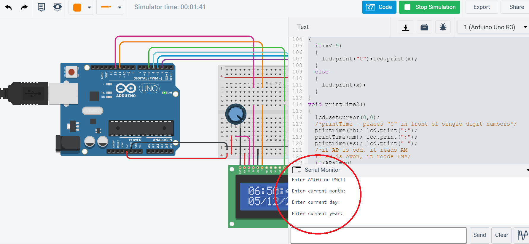
- Click on code option and then click on Serial Monitor option.
- Now click on Start Simulation and set the current time and date, just by answering simple questions like "Enter current hour:", "Enter current minute:", "Enter current second:", "Enter AM (0) or PM(1)", "Enter current month:", "Enter current day:", and "Enter current year:".
Catch Sight of Digital Clock Output on the LCD
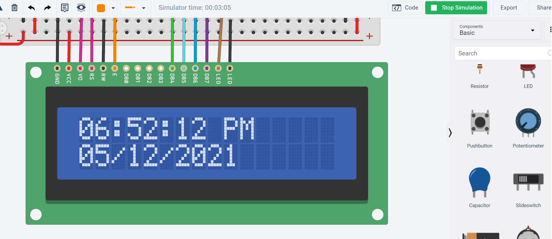
Now the Digital Clock is ready, and you can watch the time and date on it.