Digital Bell Ball Ø15
by smartsportassistance in Workshop > Science
491 Views, 4 Favorites, 0 Comments
Digital Bell Ball Ø15


The Idea of the digital bell ball
The classic bell ball is used in sports for the blind, for example the Paralympic sport of goalball uses such a ball. The sound of the bell inside the ball enables people with visual impairments to locate the ball in space as it moves.
The version presented here is a digitalization of this ball. It is intended to enable people with visual impairments to locate the ball even when it is not moving, but also to enable people with limited vision to locate the ball using light signals. Users should also be able to distinguish at any time whether the ball is moving or stationary.
To achieve this version, a classic bell ball was modified. The ball has been fitted with a microcontroller equipped with motion detection. This information can now be transmitted to LEDs that can light up in different colors and buzzers that can beep at different pitches and frequencies.
An app now allows users to set the LED color and the buzzer pitch and frequency depending on whether the ball is moving or stationary.
Downloads
Supplies


Materials
- Bell ball Ø15
- Soft foam ball Ø14
- 9V Rechargeable battery
- RS PRO battery holder
- Arduino Nano 33BLE
- Seeed Studio Base shield
- M2x20mm Machine screws
- M2 Hexagon full nuts
- M2x5mm Machine screws
- WS2813 LED Strip
- Seeed Buzzer
- Slide switch
- USB-C adapter (type C Male to micro usb female)
- USB 2.0 adapter, C socket to 2x Micro-B connector, Y cable, 0.3
- Seeed Studio Grove-Kabel, Stem, Twig (4 Pin connector)
- Insulated copper wire 4-core, 4 x 0.25 mm²
- Electric 2 core cabel 2x 0.75mm²
- UHU Plus quick Resistant Double chamber Syringe
- M4 Machine screws 30mm or more
- M4 Hexagon full nuts
Tools
- 3D printer
- PLA tought filament (3d Printer material)
- Duct tape
- Soldering equipment (+soldering tin, desoldering pump)
- Wire stripper
- Scissors
- Cutter
3D Part Printing + Cutting Ball Open


The following 8 parts have to be downloaded and printed we recomend ussing PLA tought filament ( but simmilar materials can also be used ).Support filament is required for one of the parts.
https://ucloud.univie.ac.at/index.php/s/maNjkBi4gNa7SqC
4 different types of brackets are required ( LED-,USB-,buzzer-,switch-bracket) each bracket consists of 2 parts, the lid and the base.
for 1 bell ball we need:
- 14x LED-bracket (base and lid)
- 4x Buzzer-bracket (base and lid)
- 1x USB-bracket (base and lid)
- 1x Switch-bracket (base and lid)
so a total of 40 parts has to be printed.
Tip: in Figure 2 and 3 you can see the recommend orientation to minimize the additional post-processing, and 0.2mm is a good printing layer height because it offers a good compromise between speed and accuracy.
These printed parts later will be inserted in the ball, which can be cut open using a cutterknife (Figure 4).
Ball Clamp


To make it easier to glue the ball together, an optional clamp was designed, which can also be found in the ZIP folder under “CAD parts”.
Figure A shows how the parts should be aligned in the slicing software to minimize the need for additional post-processing.
The parts shown here must each be printed twice. To assemble, plug together “clamp 1”, “clamp 2” and a “base” (figure B) and then screw the 2 clamp halves together with nuts and bolts.
Buzzer Preparation & Assembly
.png)
.png)
.png)
.png)
.png)
.png)
Buzzer cable preparation
The cables supplied in the buzzer packaging are cut to a remaining length of approx. 10 cm.
The tips of the 4 cable ends are stripped, then the cable strands are twisted, and a light layer of solder is applied to them (Figure 5).
Buzzer Preparation
First, remove the plug connection (= white plastic part) from the circuit board as in Figure 6 (Tip: Place the cutter knife between the circuit board and the adapter and then slowly pull the cover off the pins using leverage.). Then remove the pins one by one using the soldering iron (Figure 7). Finally, free the contact holes from any soldering tin residues using the desoldering pump (Figure 8).
Buzzer soldering
Insert the four wires of the cables from below so that the strands come out on the top of the boards (Figure 9). Now solder the prepared buzzer cable to the buzzer board the black cable on the J1 side and the yellow cable on the R1 side (Figure 10).
LED Assembly
.png)
.png)
.png)
.png)
LED preparation
The next step is to prepare the LEDs. Cut 14 individual LEDs from the LED strip so that they look like in Figure 11 (Tip: Work as precisely as possible and divide the copper contacts exactly in the middle. This makes soldering much easier). Then place a drop of solder on each of the eight contact points.
LED cable preparation
Cut a total of 13 pieces of the 4-pole cable with a length of approximately 10 cm. Finally, strip the insulation from both ends of each cable, twist the strands and apply a light layer of solder on them (Figure 12).
LED strip assembly
Now the cables are soldered to the individual LEDs. Care must be taken to ensure that the same connection is always soldered to the same connection. For example, “Ground” must always be soldered to a different “Ground” connection across all 14 LEDs with one cable. Attention must also be paid to the small black arrow on each LED they must always point in the same direction from start to finish, with the tip pointing towards the end (Figure 13). Do not make all the LEDs and LED cables into a long chain, but connect 7 LEDs with cables and solder an extra cable to one end of the second strip. (Note: this makes installation in the ball easier.). It is important that an extra cable is on the opposite side of the arrow on the LED (Figure 14).
LED Strip Conenction
.png)
.png)
.png)
4 pin connector on LED strip 2
A 4-pin connector is soldered to the extra LED cable soldered to band 2 in order to connect the 2 bands later on (Figure 15).
Adapter cable from LED strip 2 to microcontroler
One cut off of the buzzer cables in Step 2 is used as adapter cables. The adapter is prepared the same way by stripping the ends , twisting the strands and applying a light coat of solder.
When soldering the cable to strip 2, please observe the following exact assignment (Figure 16).
- Color adapter cable -> LED contact
- Black ->GND
- Yellow -> B1
- White -> D1
- Red -> +5V
Adapter cable from LED strip 1 to LED strip 2
One cut off of the buzzer cables in Step 2 is used as adapter cables. The adapter is prepared the same way by stripping the ends , twisting the strands and applying a light coat of solder.
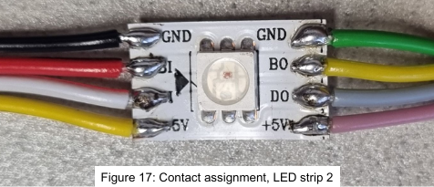
When soldering the cable to strip 1, please observe the following exact assignment (Figure 17).
- Color adapter cable -> LED contact
- Black ->GND
- Red -> B1
- White -> D1
- Yellow -> +5V
Switch and Battery
.png)
.png)

Battery adapter
Continue with the installation of the battery adapter. First, two individual cables must be prepared. As with the LED strip, only this time with a length of 10 cm and thicker cables. To do this, a 2-core cable must be cut to a length of 10 cm and both cores prepared for soldering (note: strip the insulation + apply solder to the cores). The standard cables attached to the battery adapter must be desoldered and the prepared two-core cable soldered in its place (Figure 18). Reason for replacing the cable: excessive current during operation would cause the thinner cable to melt.
Connection to switch
Finally, the on/off switch of the digital doorbell is soldered. To do this, cut another thin cable to 10 cm, strip the insulation and apply solder to the strands. The 3D printed base and the cover of the switch holder must then be threaded onto the thick cable on the battery adapter. It is best to do this in the ball, which has already been cut open (figure 19).
Now solder the thick cable to one of the two outer contacts of the switch (note: the direction does not matter), while the thin cable that has just been prepared is soldered to the middle contact of the switch (figure 20).
Microcontroller
.png)
.png)
.png)
.png)
.png)
Base station
The two remaining cables from the previously assembled switch/battery unit are soldered to the circuit board to complete the circuit. To do this, the cable leading away from the battery must be soldered to “GND” on the circuit board and the cable leading away from the switch must be soldered to “VIN” on the circuit board. As shown in Figure 33.
Arduino
If the Arduino arrives without a soldered connector strip, the two connector strips must be soldered on.
Now plug the Arduino into the two yellow sockets on the base station, paying attention to the orientation. The USB socket of the inserted Arduino must be on the same side as the USB label on the base station (Figure 30).
To fix the Arduino in place, prepare two cables, each 6 cm long (note: strip the cable ends + apply solder to the cable strands) and insert them through the holes in the corners of the Arduino (Figure 31). The two ends of the cable are then inserted through holes in the circuit board and then soldered together on the underside (Figure32).
The microcontroller is now ready to use (Figure 34).
Sofware Installation
.png)
.png)
.png)
.png)
.png)
.png)
The provided video will take you to every step of the Sotware installation.
- To install the program on the Arduino, a micro USB data cable is required to connect the microcontroller to the computer.
- First, the Arduino IDE software for the specific operating system must be downloaded and then installed. At the same time, the program for the Arduino can also be downloaded via the ZIP folder.
- Next, open the Arduino IDE software and click on “File” in the top left-hand corner.
- Then click on “Open” to open the file manager (Figure 35).
- The “Arduino_Program” must then be selected and opened under the ZIP folder (Figure 36).
- The program then asks whether a new folder may be created, which must be confirmed with “OK” (Figure 37).
- Once in the software, additional packages must first be installed. To do this, select the so-called “BOARDS MANAGER” on the left-hand side of the software. Then enter “Arduino Mbed OS Nano Boards” in the search bar. The correct package will then appear. Just click on “Install” and wait until it is ready (Figure 38).
- Next, select the so-called “LIBRARY MANAGER” on the left-hand side of the software and enter “Arduino BLE” in the search bar. As soon as the package appears, click on “Install” again (Figure 39). Then repeat this step with the terms “Arduino_LSM9DS1” and “nRF52_MBED_PWM”.
- Now connect the Arduino to the computer using a micro USB data cable, make sure that the orange LED on the Arduino flashes. If not: Press the small button on the Arduino twice in quick succession.
- Click on “Select Board” at the top of the software and select the Arduino (Figure 40)
- Finally, press “Upload” (the arrow pointing to the right) and wait until the program has finished uploading to the Arduino. This may take 1–2 minutes.
- The "klingelball app" should now be downloaded from the App Store or the Google Play Store, and it should be tested if it is possible to connect the app with the microcontroller.
- The Arduino can now be unplugged from the computer and used for the doorbell ball.
Bell Ball Assembly


.png)
.png)
.png)

Component Testing
The individual components can now be connected to the base station to test the function of the individual components. This is tested using the corresponding bell ball app. If the buzzers and LED strips are working, you can start assembling them.
The base station has eight slots, of which only five are used. The buzzers must be plugged into slots “D2”, “D4”, “D6” and “UART”, while the adapter cable with the cross-soldered black cable from LED strip 1 must be plugged into slot “A0After testing deplug the component for the assembly (Figure 27).
Ball Assembly
First, the components that have just been created are connected to the 3D parts that have already been printed. The bases of the LED holders are threaded 7 times onto each of the two LED strips (Figure 21). A base of the buzzer holder is threaded onto each of the buzzers (Figure 22). The base of the USB holder is threaded onto the USB splitter and glued together with a 2- component epoxy resin adhesive (Figure 23)
Next, the parts are installed in the cut-open doorbell ball. To do this, the USB splitter, two buzzers and LED strip 1 are installed in the first half of the ball, while the switch (Figure 25), two buzzers, the switch and LED strip 2 are installed in the second half of the ball (Figure 24). All components are inserted into one of the holes from the inside of the ball and covered with the corresponding (buzzer, LED, USB, switch) cover from the outside. Then insert 2 screws per component into the holes from the outside and fasten them with a nut from the inside. Now just tighten the screws with a screwdriver.
A foam ball is used so that the base station and the battery do not lie around loose in the ball. The foam ball is cut open and slightly hollowed out so that there is enough space for the base station and the battery (Figure 26). The material from the ball can then be used to fix the parts inside the ball. The circuit board should be positioned as centrally as possible in the foam ball. The foam ball is then inserted into the bell ball.
Now all the cables still need to be connected to the circuit board.
The two ends of the USB splitter are also plugged in. The micro-USB to USB-C adapter is first plugged into the cable without writing. The cables can now be connected, whereby the micro USB cable is connected to the Arduino on the base station and the USB-C adapter is connected to the battery (Figure 28). Tip: The plug connection in Figure 28 should be wrapped a few more times with duct tape for improved durability.
To ensure that everything works properly later, all the functions of the ball are now tested again. The “Operating instructions” contained in the ZIP folder will help you with this.
Finally, the bell ball is closed again. Place both halves of the ball on the table and have a screw clamp within easy reach. First mix the 2-component epoxy resin adhesive in a plastic container so that the components mix well and then apply the adhesive to one of the two halves of the ball. As soon as the entire contact surface has been coated with a layer of adhesive, the second half of the ball can now be placed on top of the first. The ball can now be clamped using a screw clamp. The purpose of using a screw clamp is to exert sufficient pressure on the glued area (Figure 29). Ideally, leave the glue to dry overnight in the clamped position. The digital bell ball is now ready.
The finished ball can now be tested for functionality using the corresponding app. When the ball is in motion, the pitch and beeping should change compared to when it is stationary. You can make changes yourself, for example to make the LEDs light up in the desired color or the buzzers beep and sound at different pitches. For further information on using and controlling the ball, please refer to the operating instructions.