Dianoga Chlorine Float With Fusion 360 and Old Parts
by Angus Murdoch in Outside > Water
675 Views, 0 Favorites, 0 Comments
Dianoga Chlorine Float With Fusion 360 and Old Parts
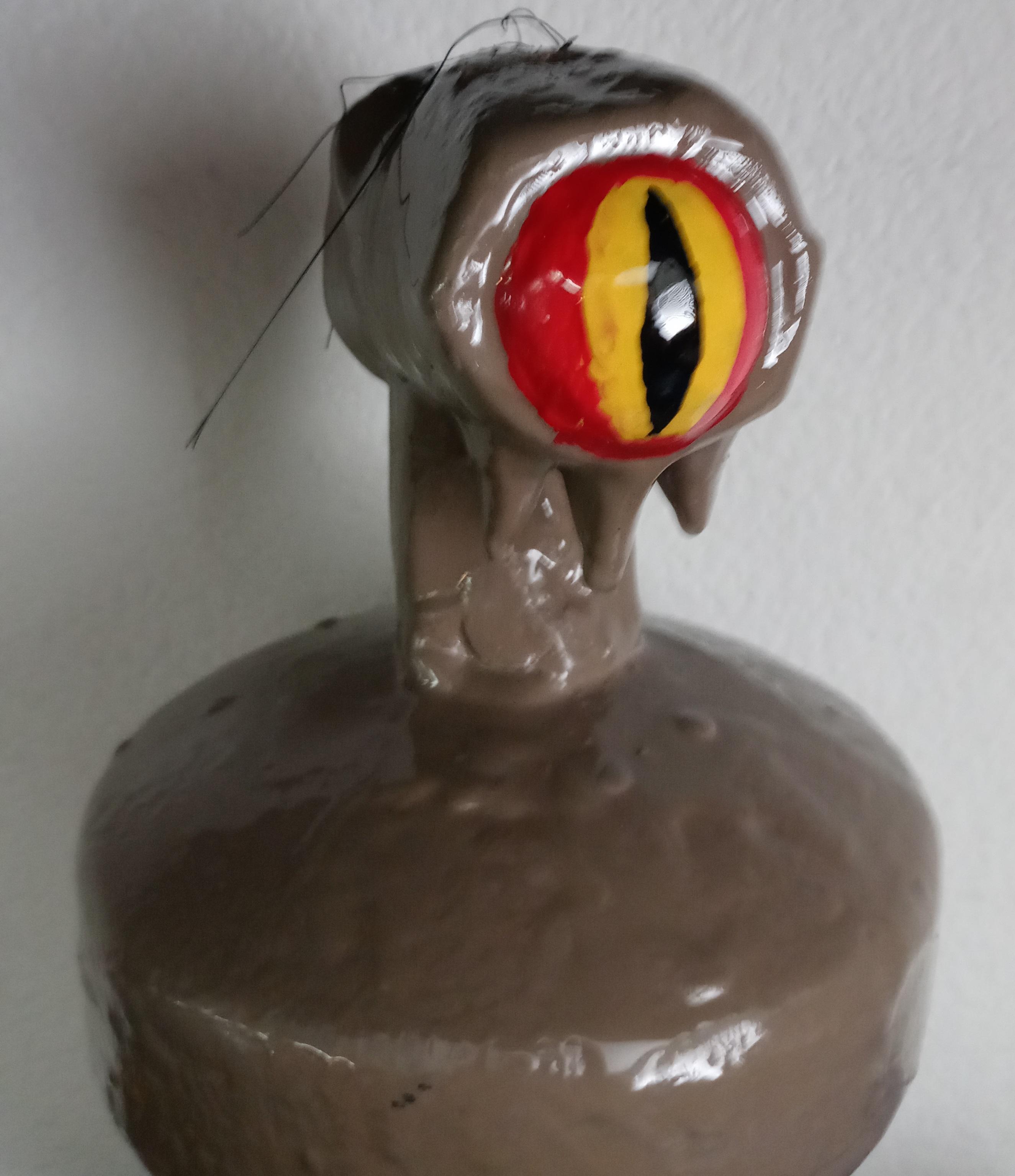
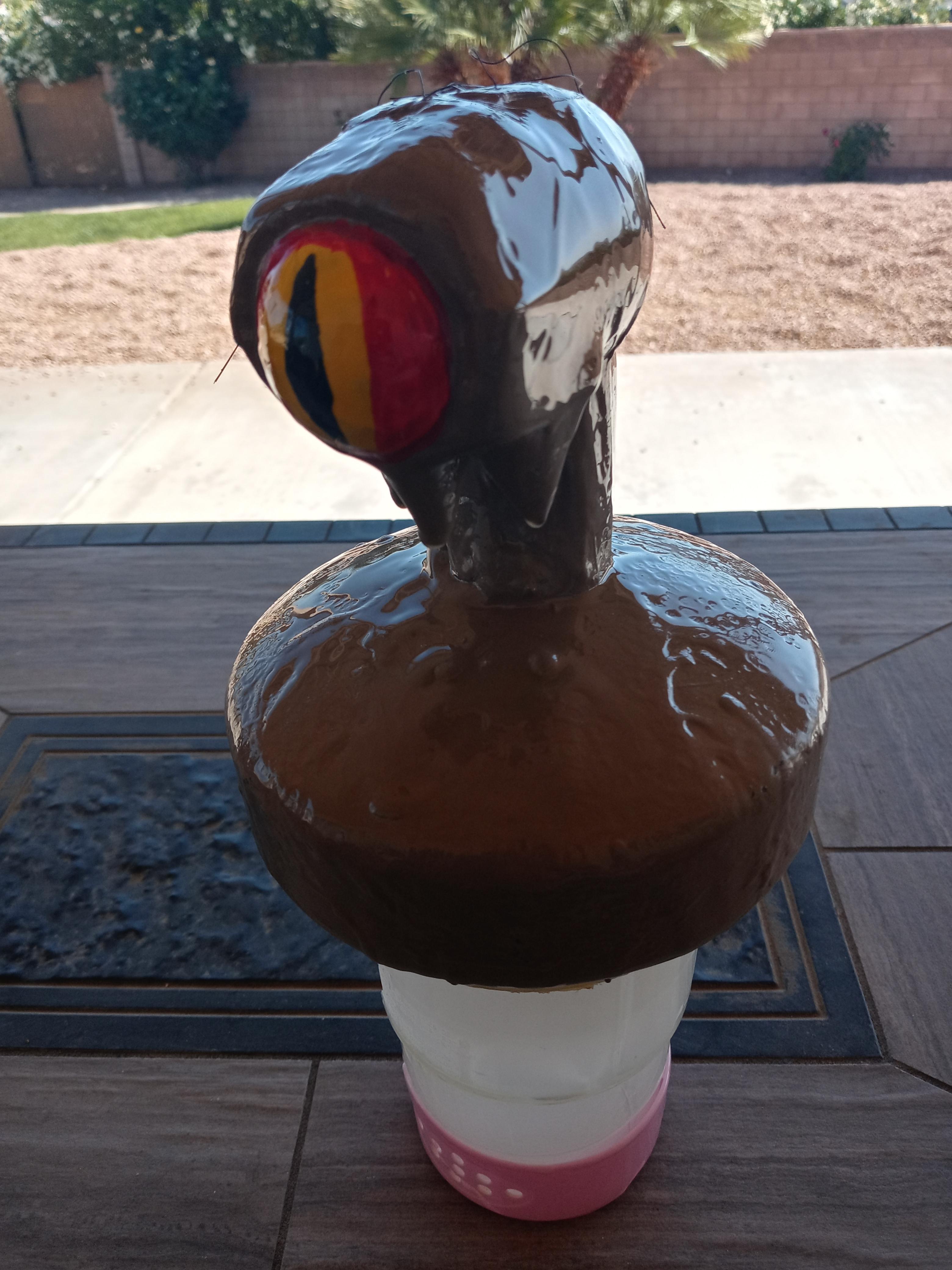
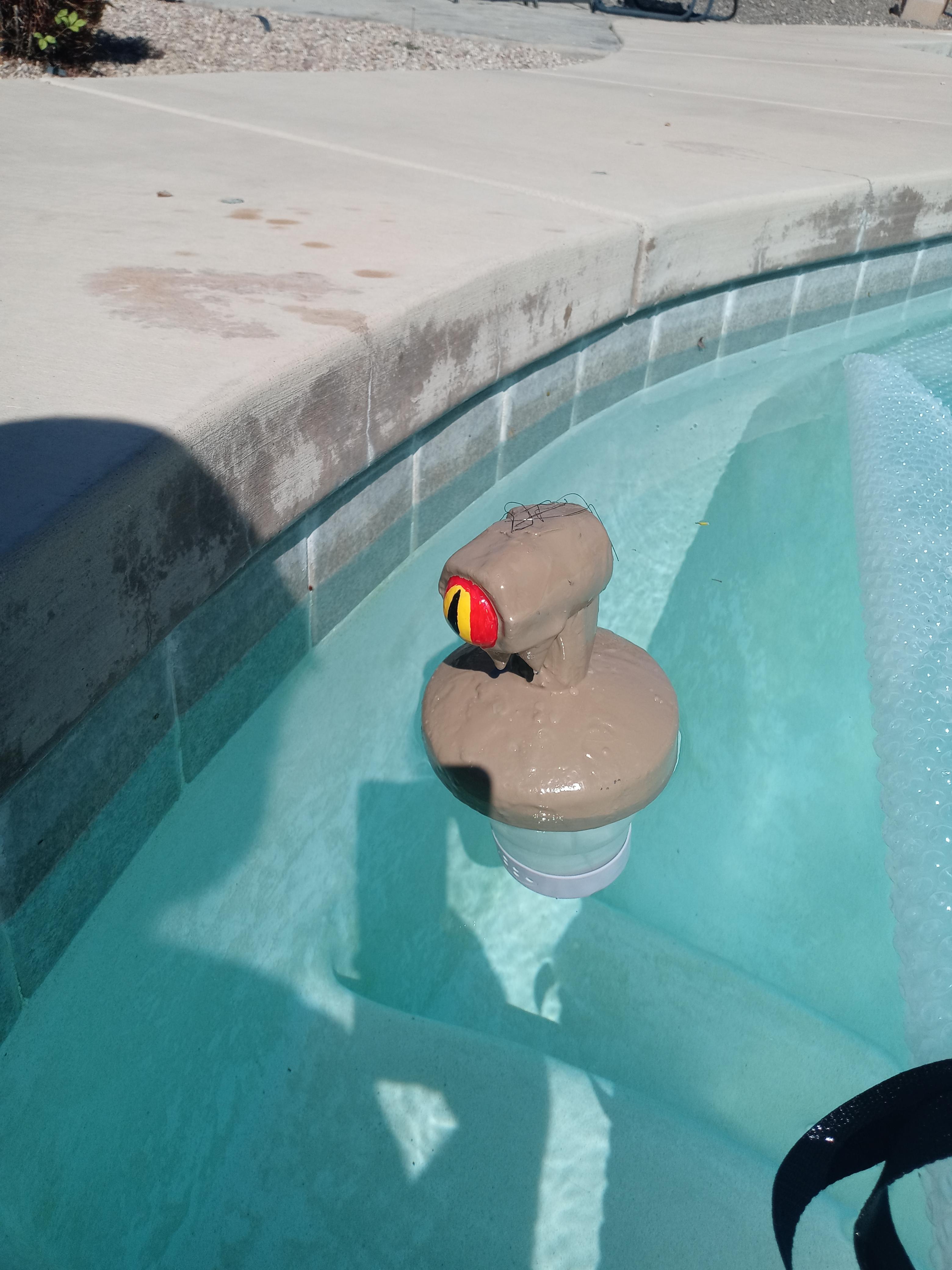
I had an old unicorn float that kept taking on water and sinking to the bottom of my pool. I could have found the small hole and sealed it but I wasn't sure if the seam would split again and figured I could make a way cooler float anyway.
I have been 3d modeling for many years now, and in all that time my two programs of choice are Autodesk Fusion 360, or Blender 3D. The decision of which program to use usually comes down to if I am creating something organic like a creature in which case I would use Blender, or if making a mechanical part then I would definitely use Fusion.
What if I could get the great CAD modeling abilities from Fusion while being able to get organic shapes that we would normally have to go to another program for? That's where this project comes in.
This project is very image intensive, but hopefully in a way that helps you follow along and see the basic principals being applied.
Supplies
- Fusion 360
- Chitubox (Optional)
- 3d printer or printing service
- Old pool float
- Ruler
- Large flat blade screwdriver
- Gloves
- Eye protection
- Respirator
- Pliers
- Utility knife
- 5 or 30 minute epoxy
- XTC-3d
- Small paint brush
- Small foam brushes
- small mixing cups
- Paint spray and brush on
- Broom with black nylon bristles (optional)
- Scissors (optional)
- Lighter (optional)
- Sand Paper 200-400 grit
Design
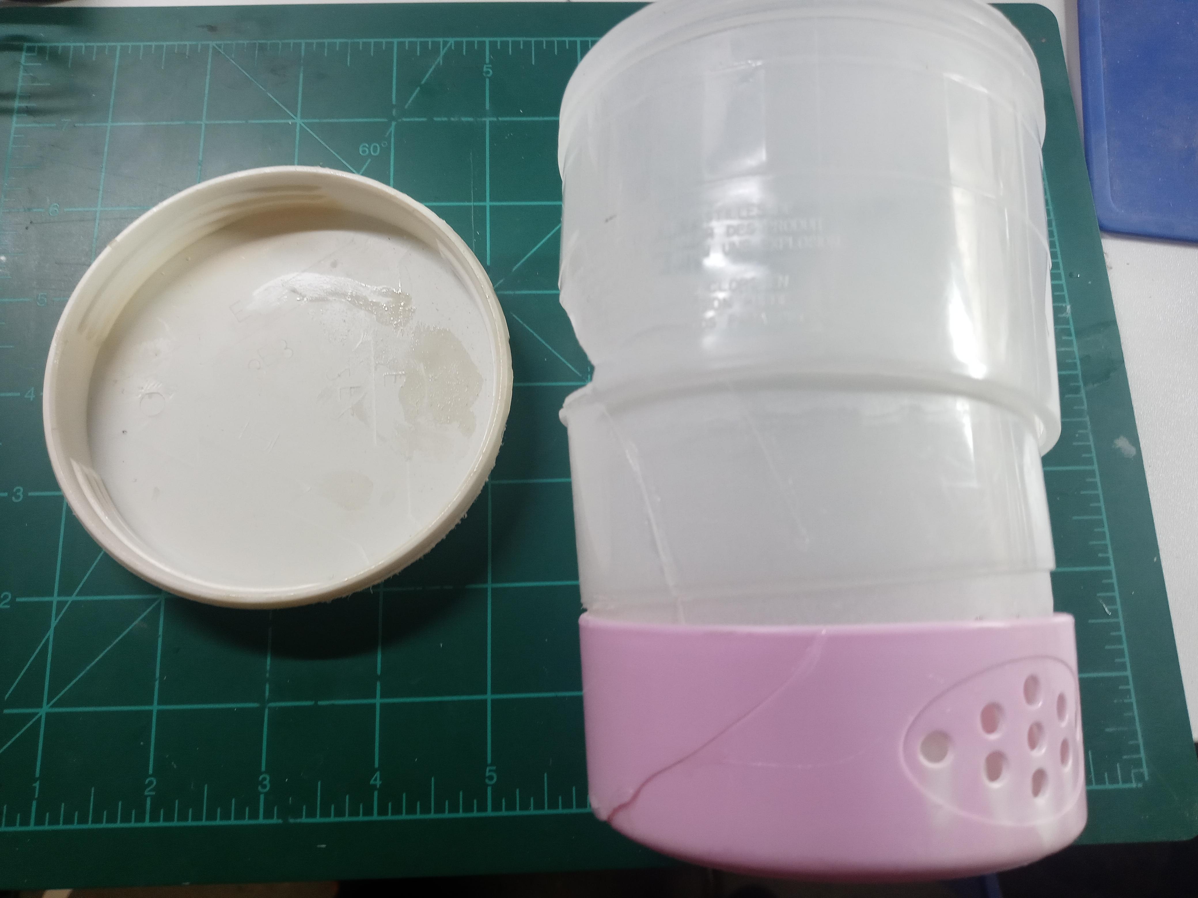
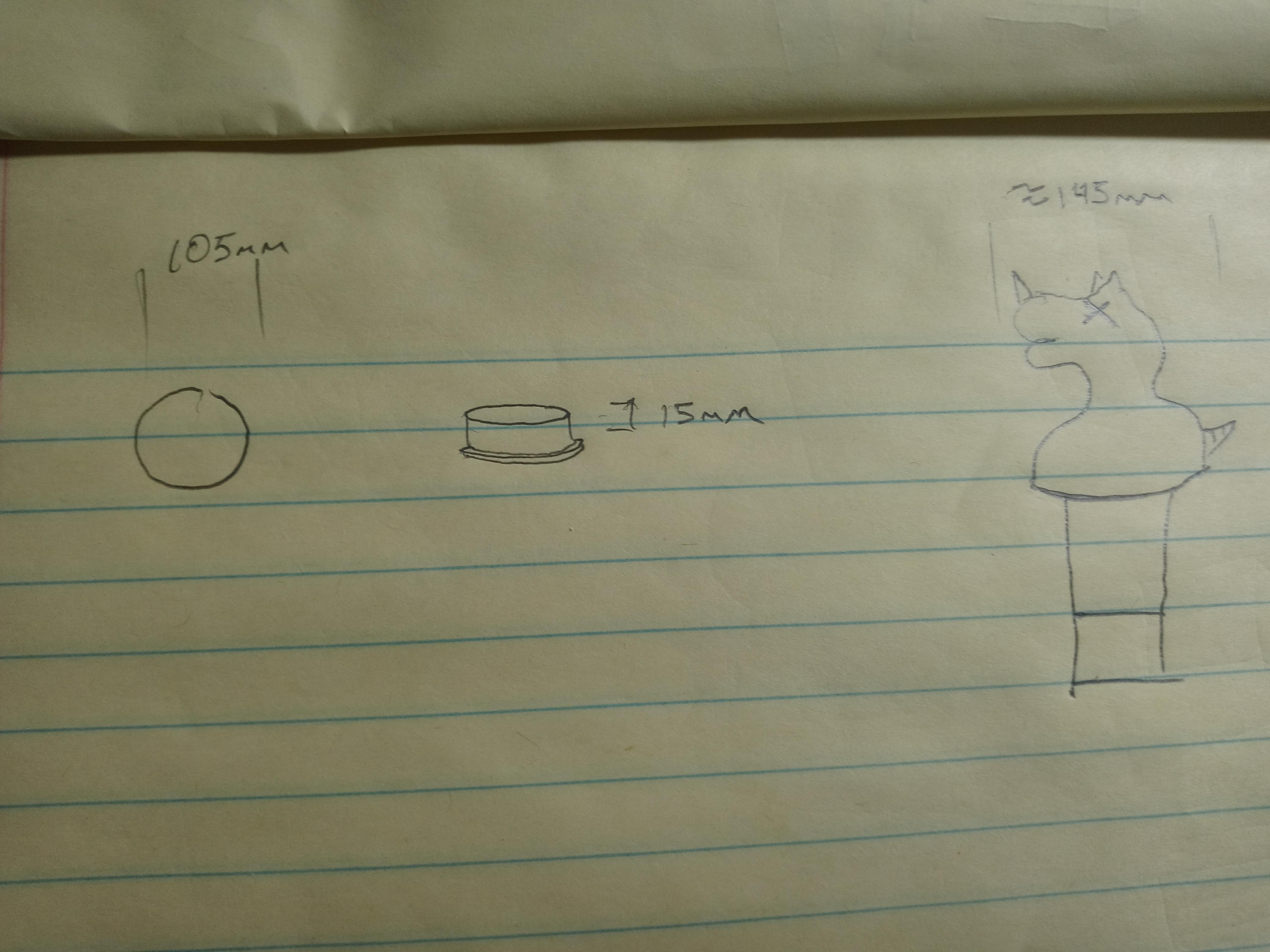
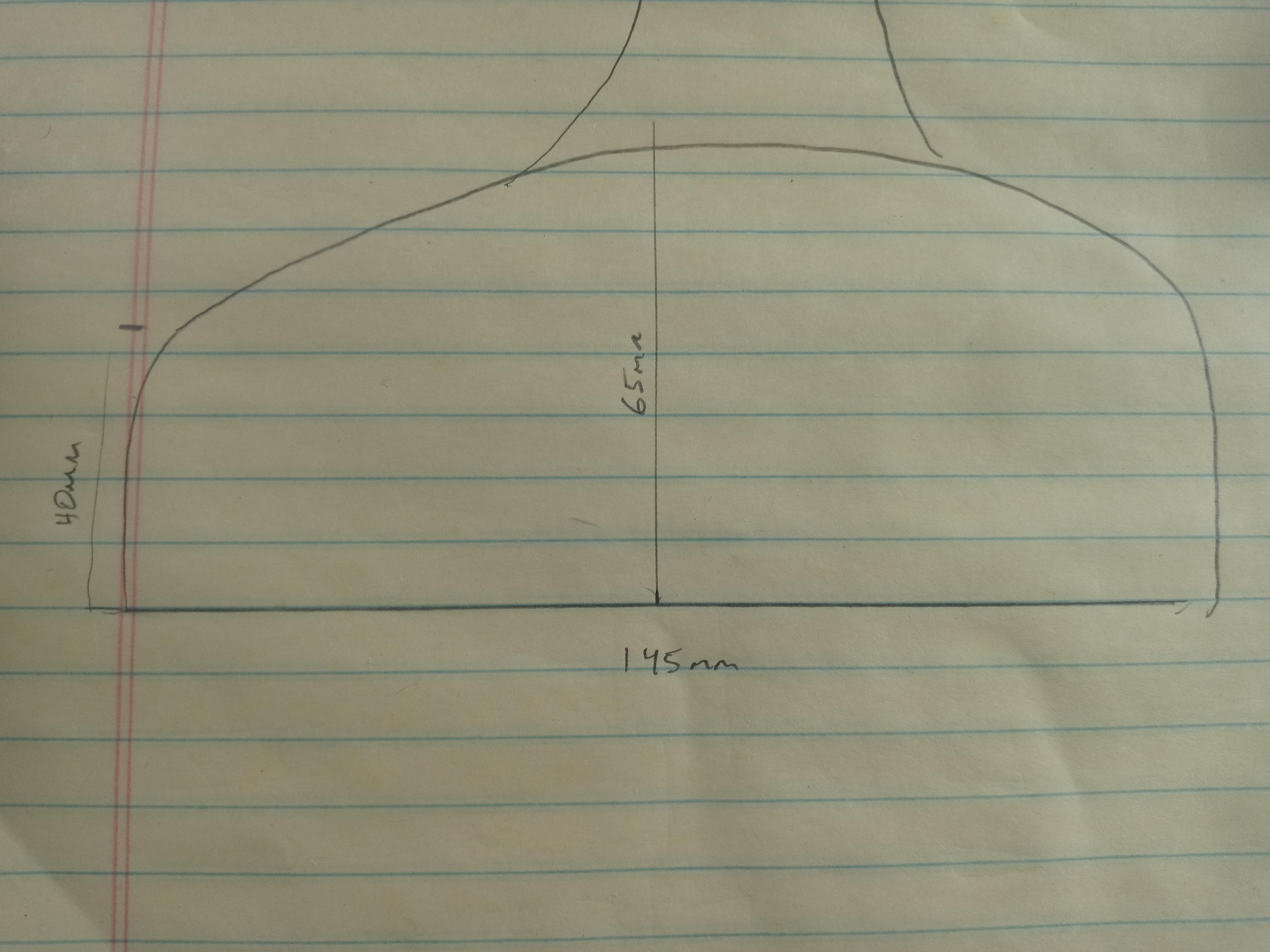
The design process in Fusion is what we are mainly going to focus on. I had already removed the base from the original float, but if you are following along you will want to carefully pry yours out with a screwdriver, carefully going around the edge.
With our base removed, take the measurements of the outside diameter and the depth. (I typically work using metric measurements as much as possible as the majority of slicing programs typically import and translate these measurements better than imperial units.)
Since we are still in the planning phase, we can take some time to draw out the rough shape of the body of our float. Now we will have some rough measurements to use when moving over to the Fusion design. Since we are making a fun design using organic shapes there is really very little measuring work that needs to be done.
Fusion Bottom Ring
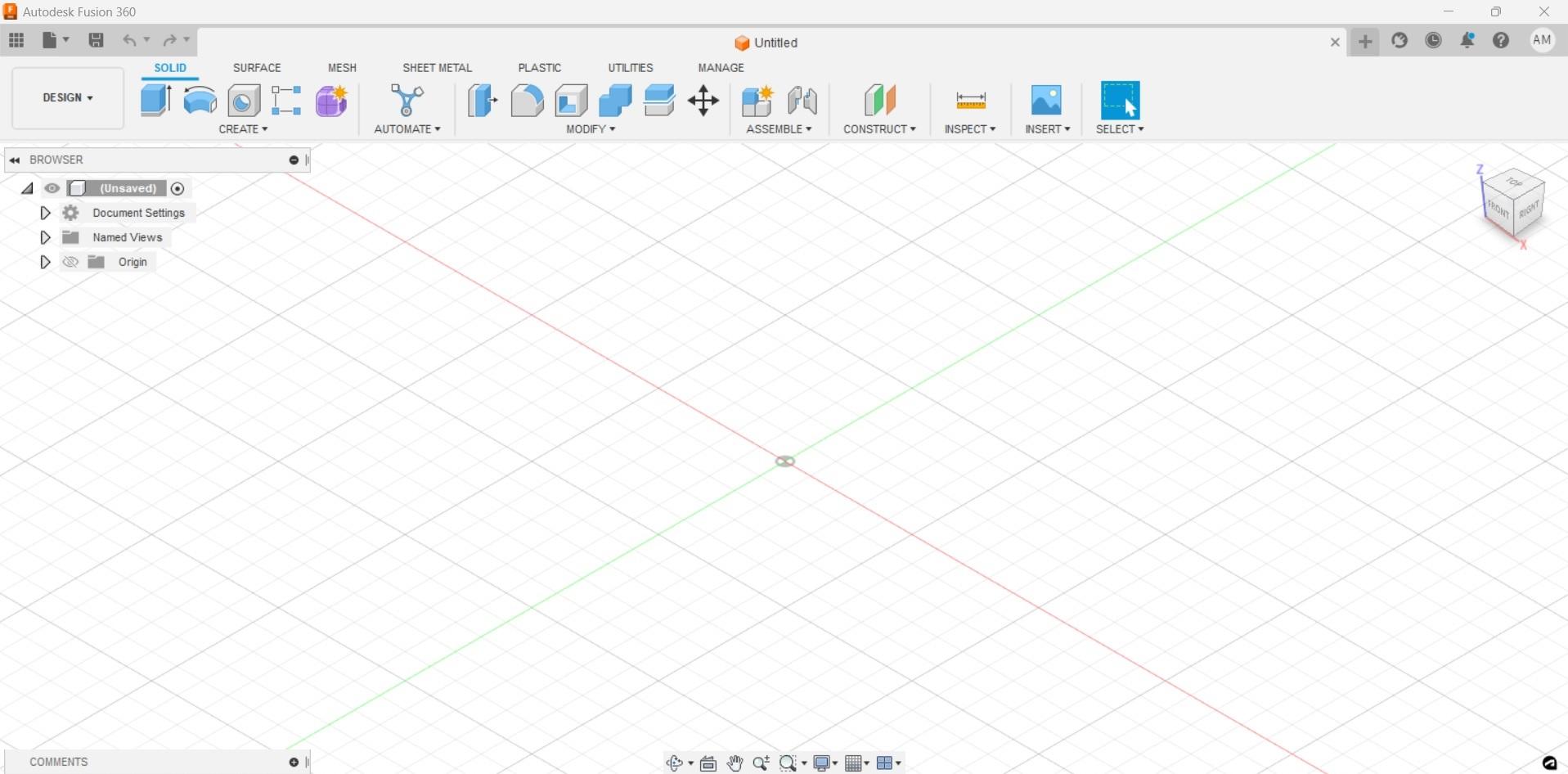
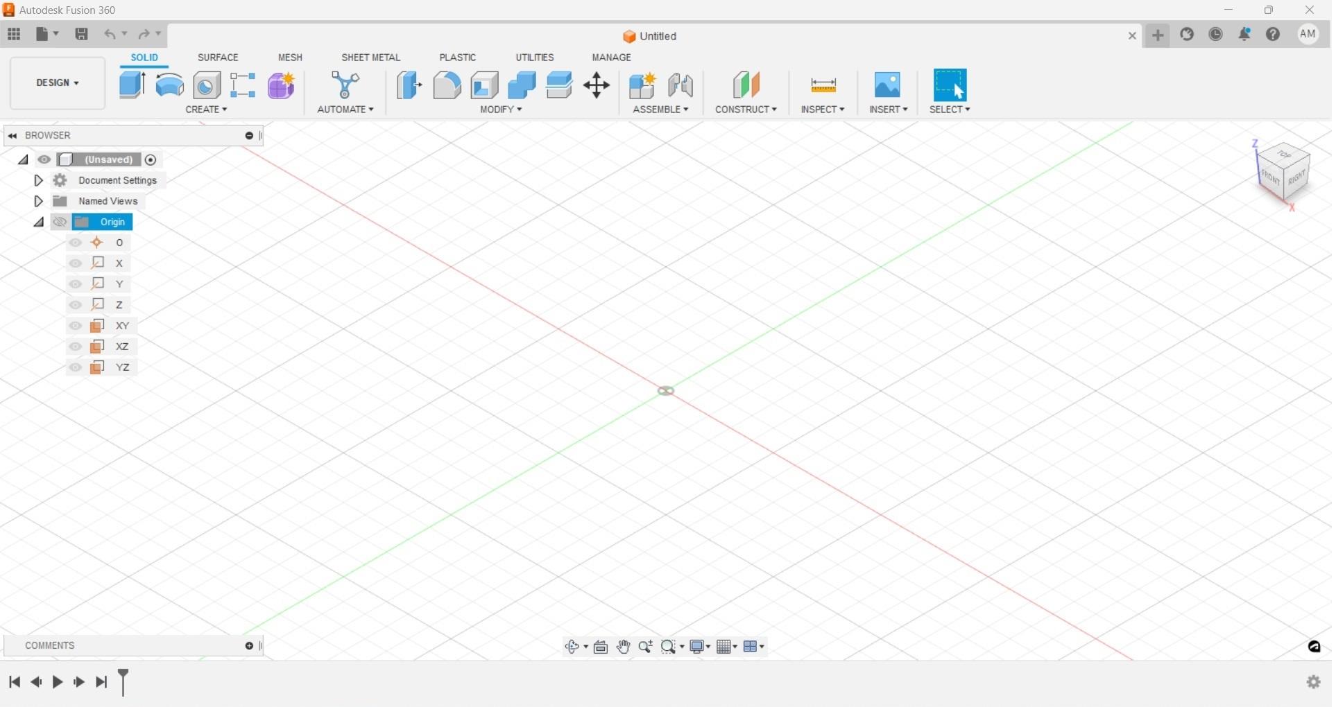
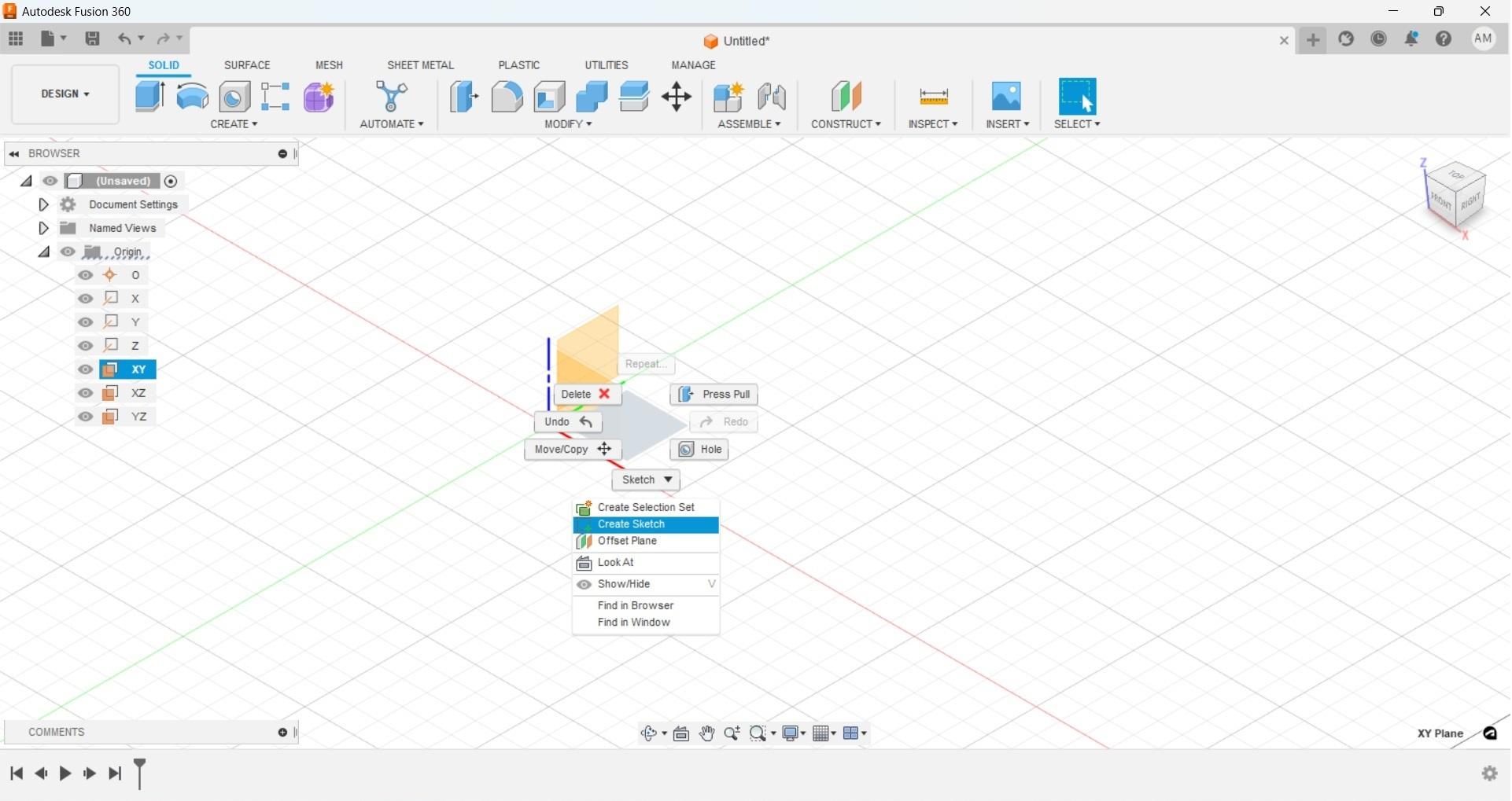
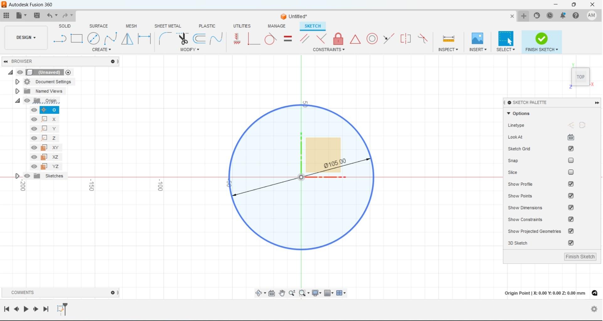
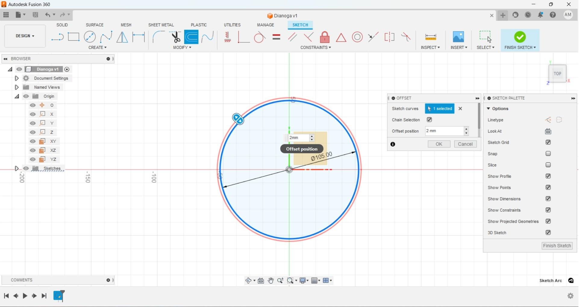
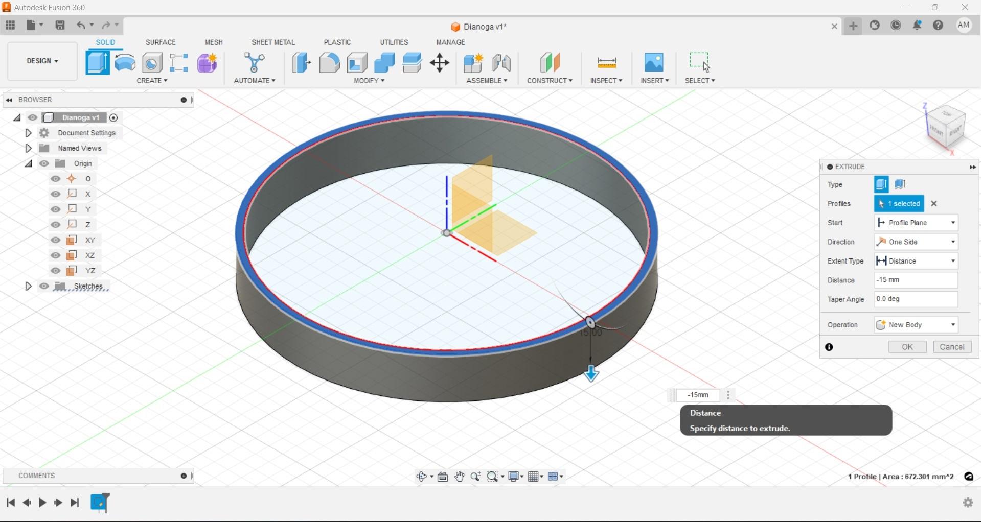
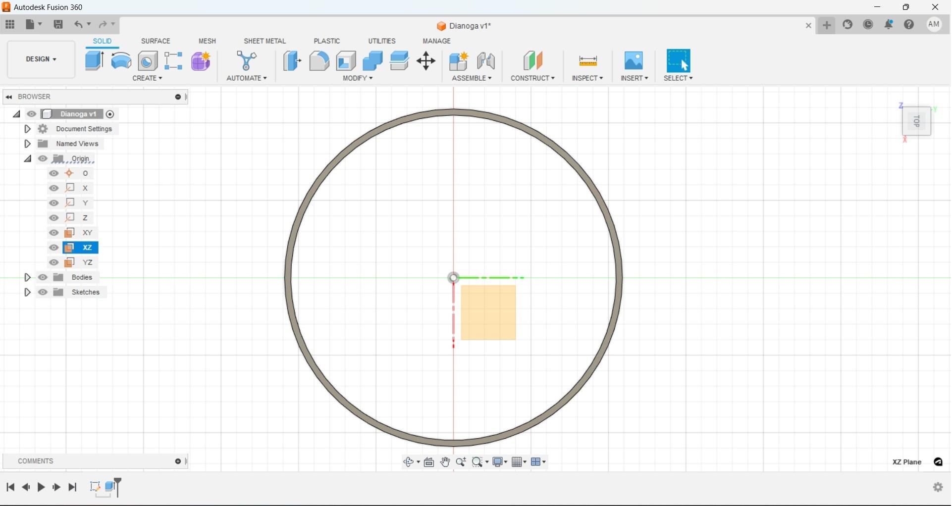
With all necessary measurements taken it's time to open up Fusion and get to the real fun. Start with turning the visibility to your origin planes on. For this bottom ring we will use the 'XY' plane. By doing this we will have our ring on the bottom of our work as it would be in the real world. A handy thing to keep in mind on origin work planes is that if you want to part to 'go' in or on a specific direction then make sure the plane you are using does not have that axis in it. So if the Z axis is up down and that is how we want our part to extrude then choose the work plane that does not have 'Z'.
Create a new sketch on the 'XY' plane, then create a circle with the center point at our origin and set the diameter to 105mm (or whatever your measurement happens to be.) This will be the inside of our ring; in the same sketch we will use the offset tool with a 2mm dimension to create the outside of the ring.
With these two circles created we can now finish our sketch. This will move us back to the main viewport where we can now make the first part of our design three dimensional. Using the extrude command select only the thin circle we created and set the distance to -15mm (or whatever measurement you have) then select "ok" on the extrusion window.
Now we should have our bottom ring showing as a solid shaded piece in our viewport. I used a negative number because I used our origin plane as the start point. Rather than having to offset another plane or create a sketch on our next piece we can use the same plane as a reference when we design our body in the positive 'Z' axis.
Fusion Body
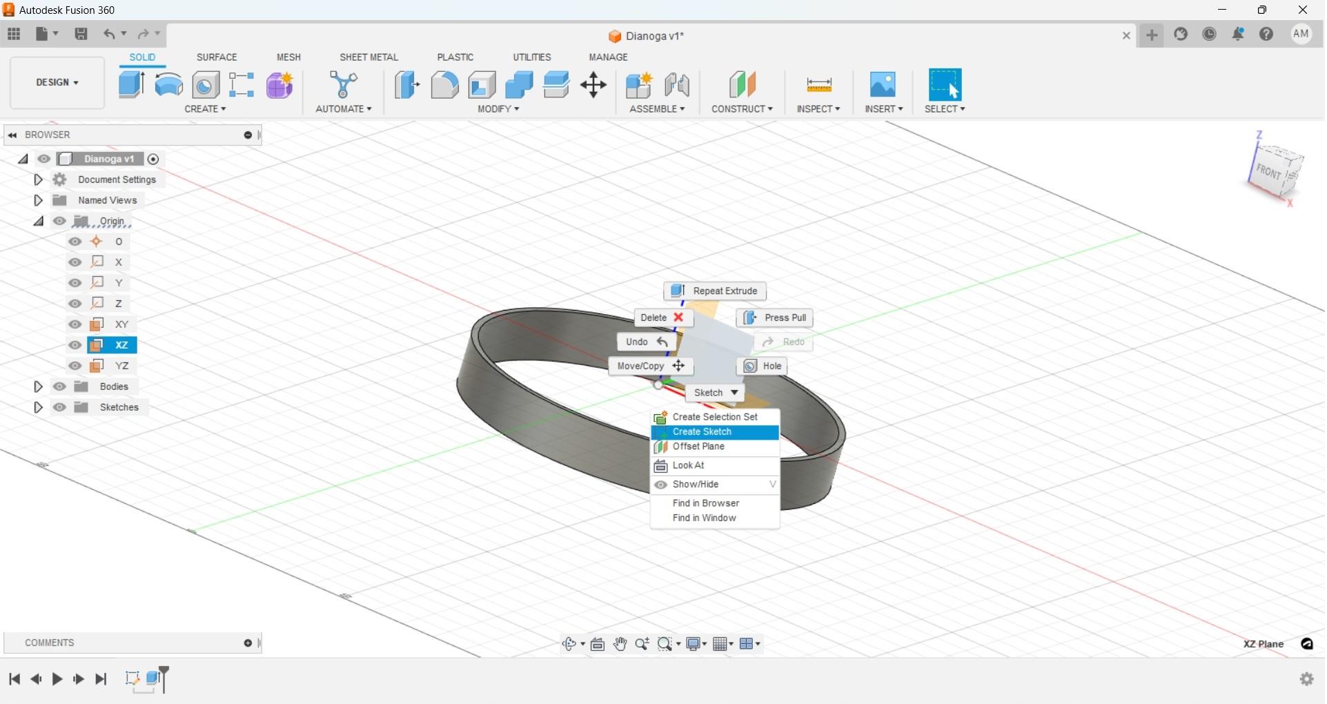
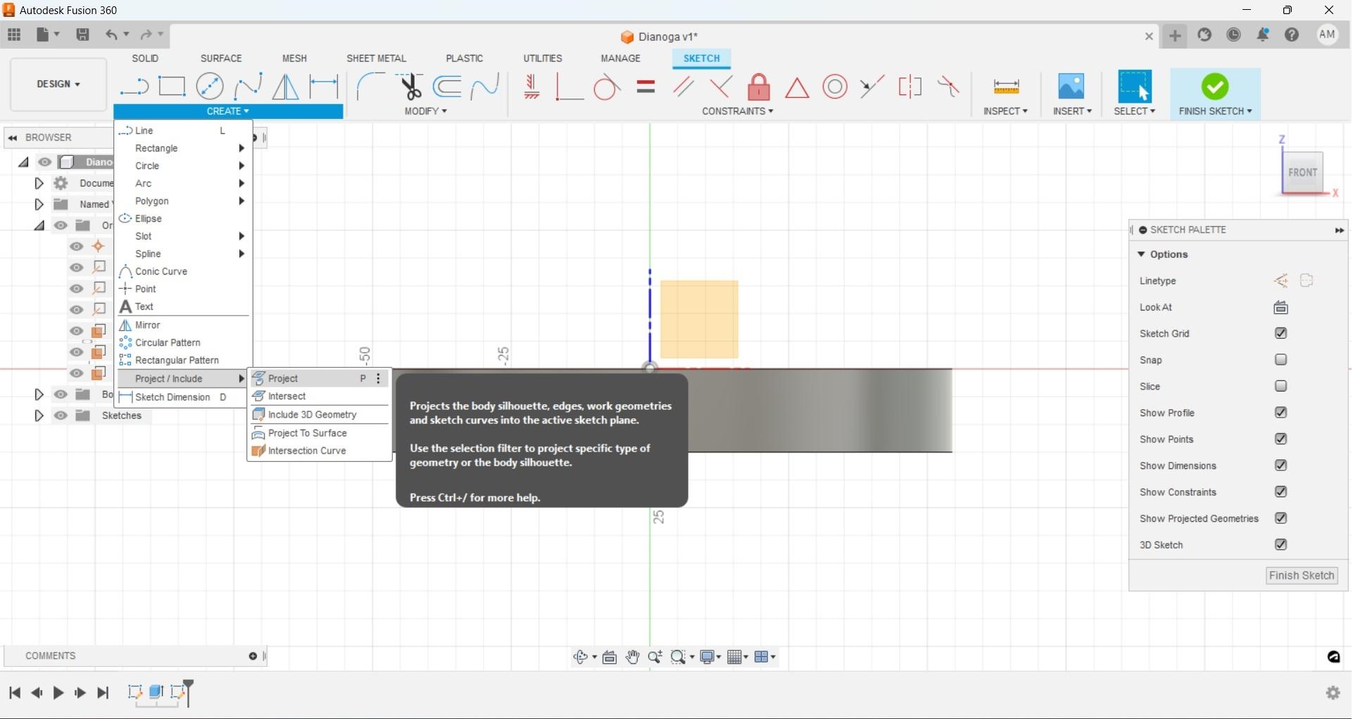
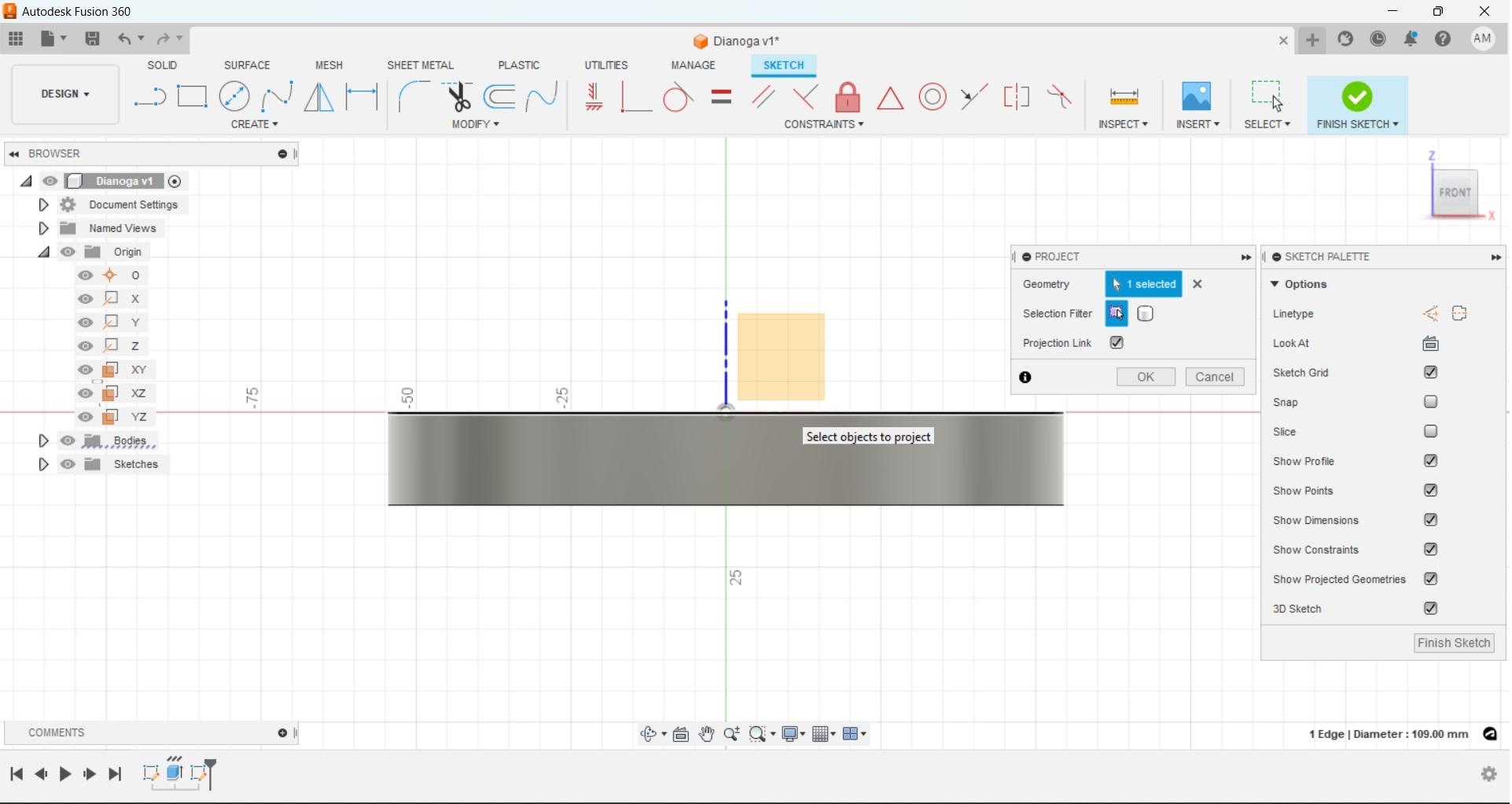
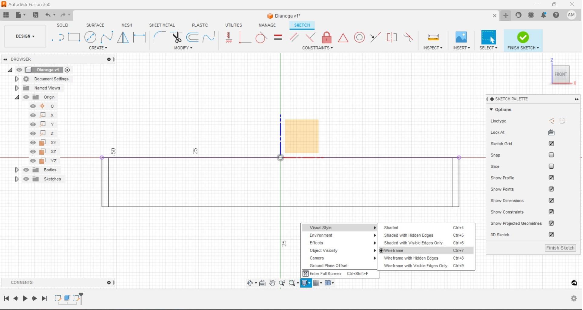
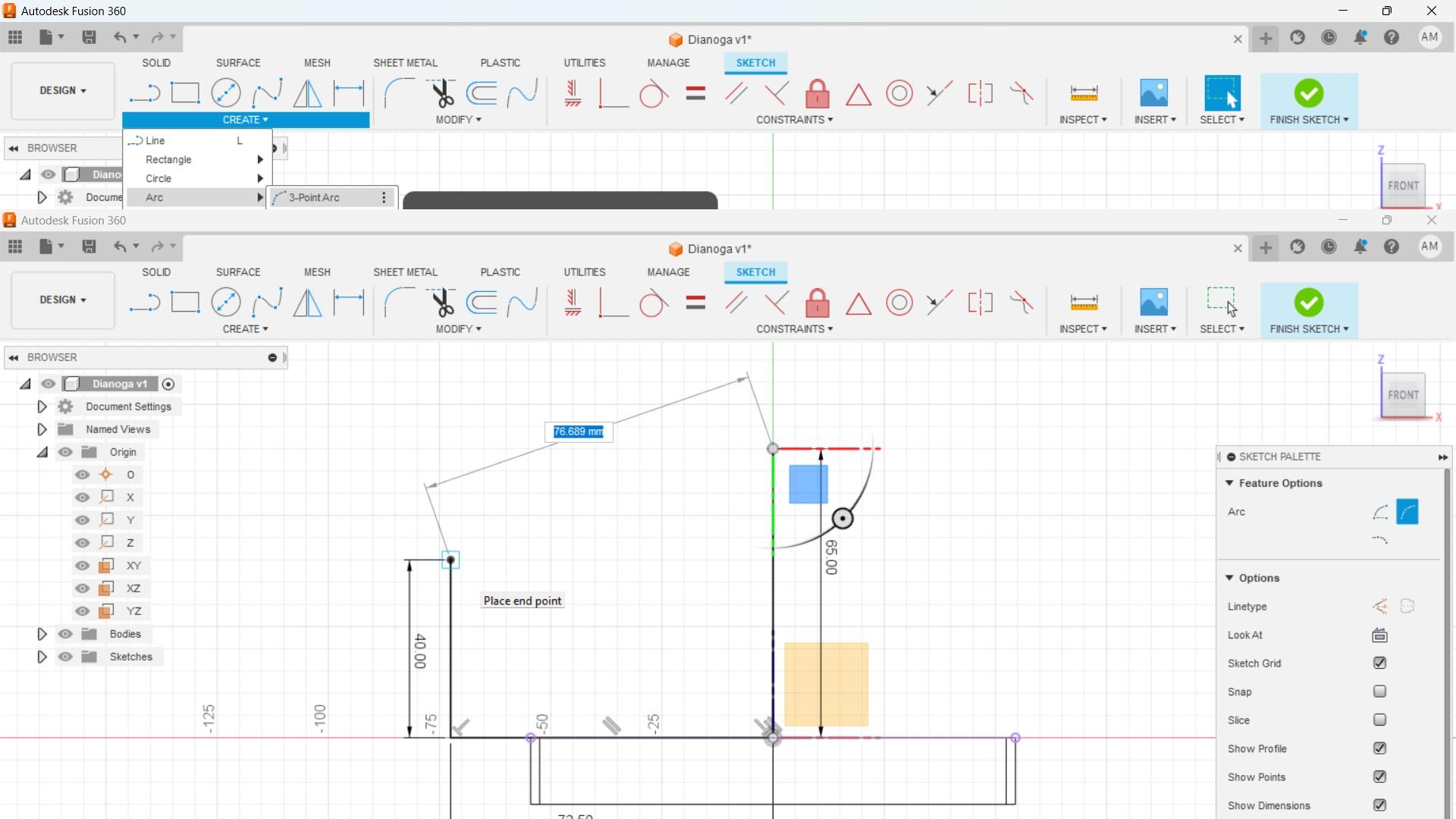
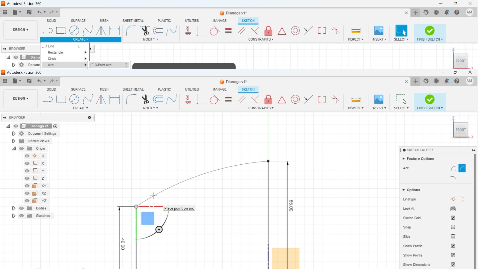
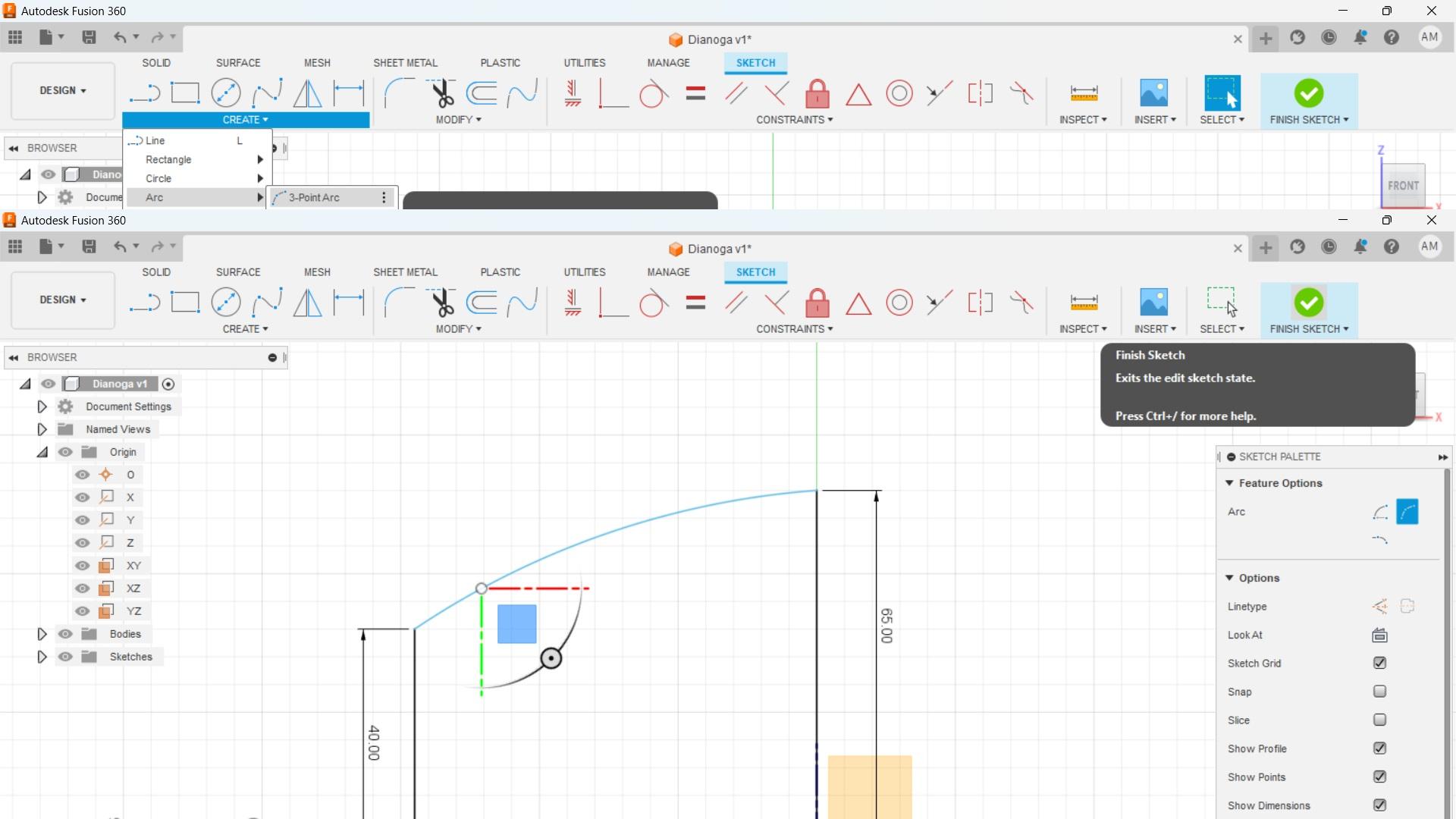
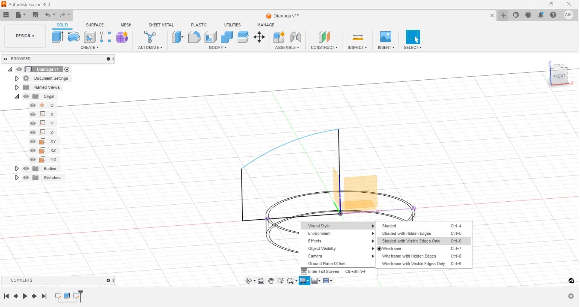
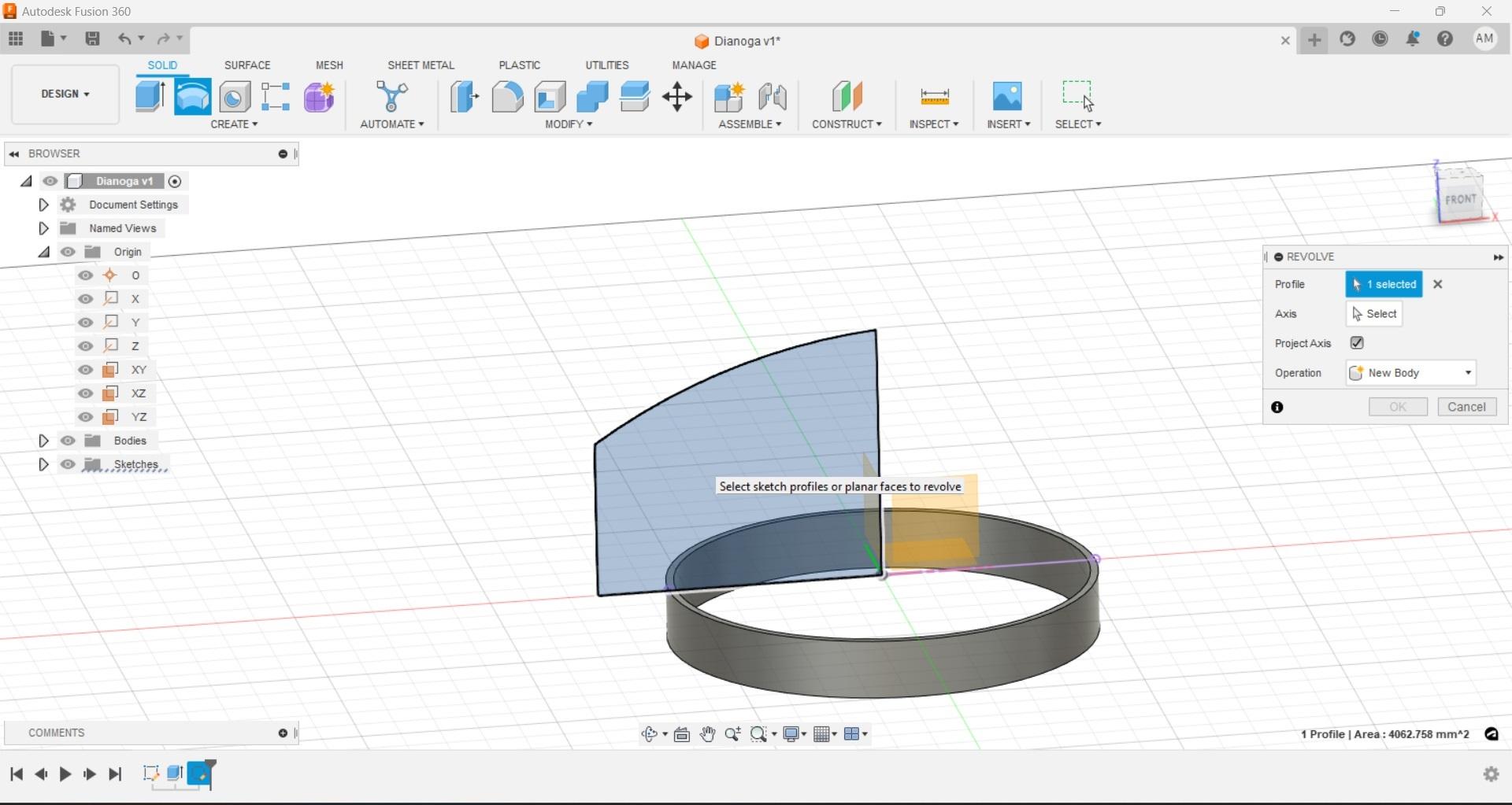
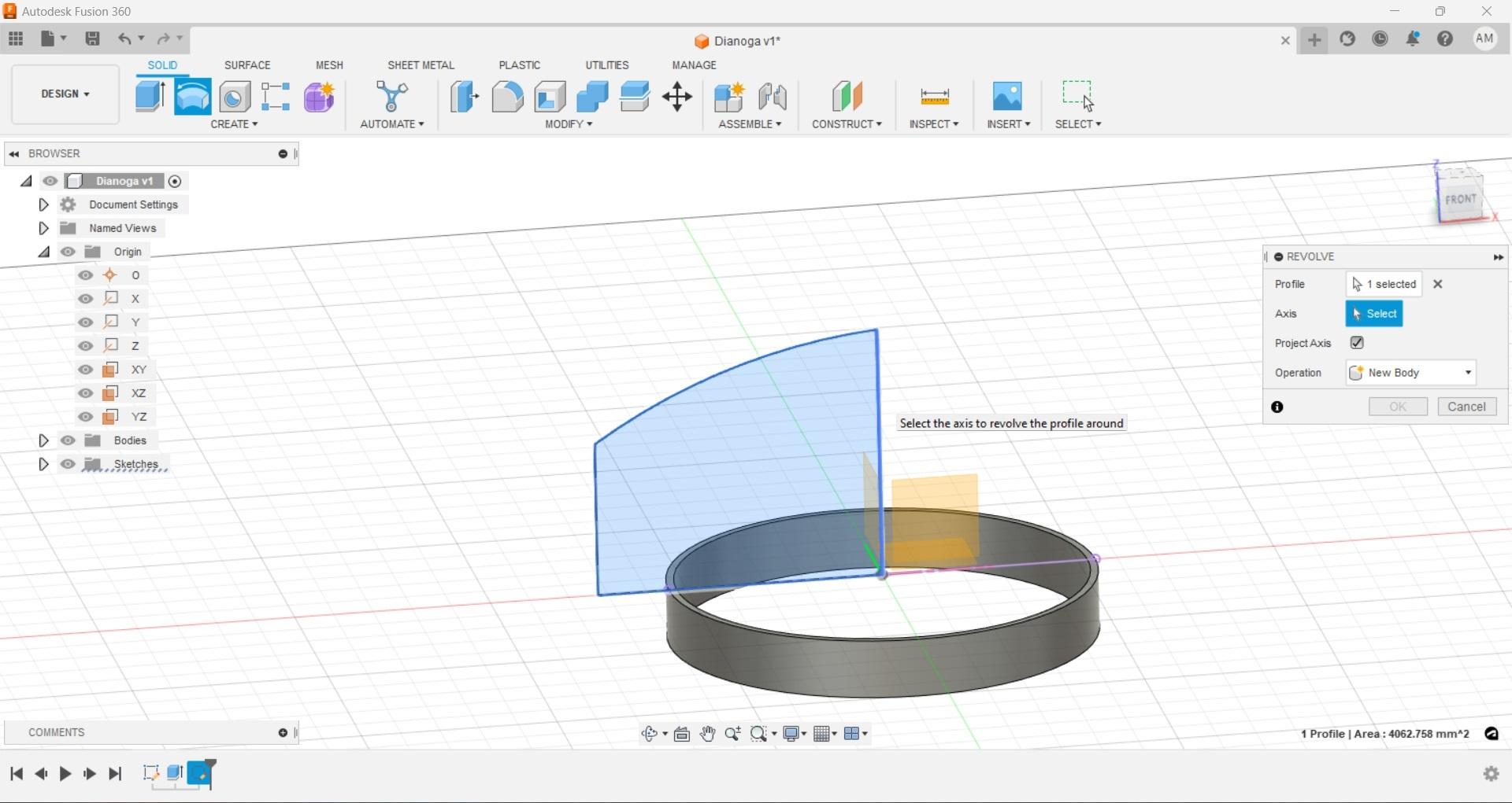
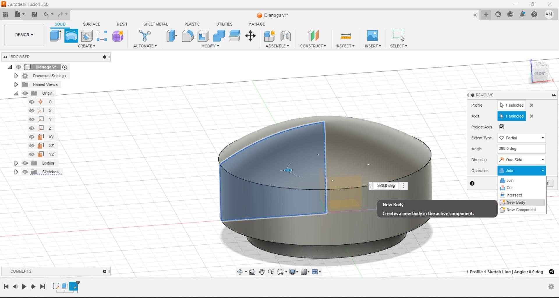
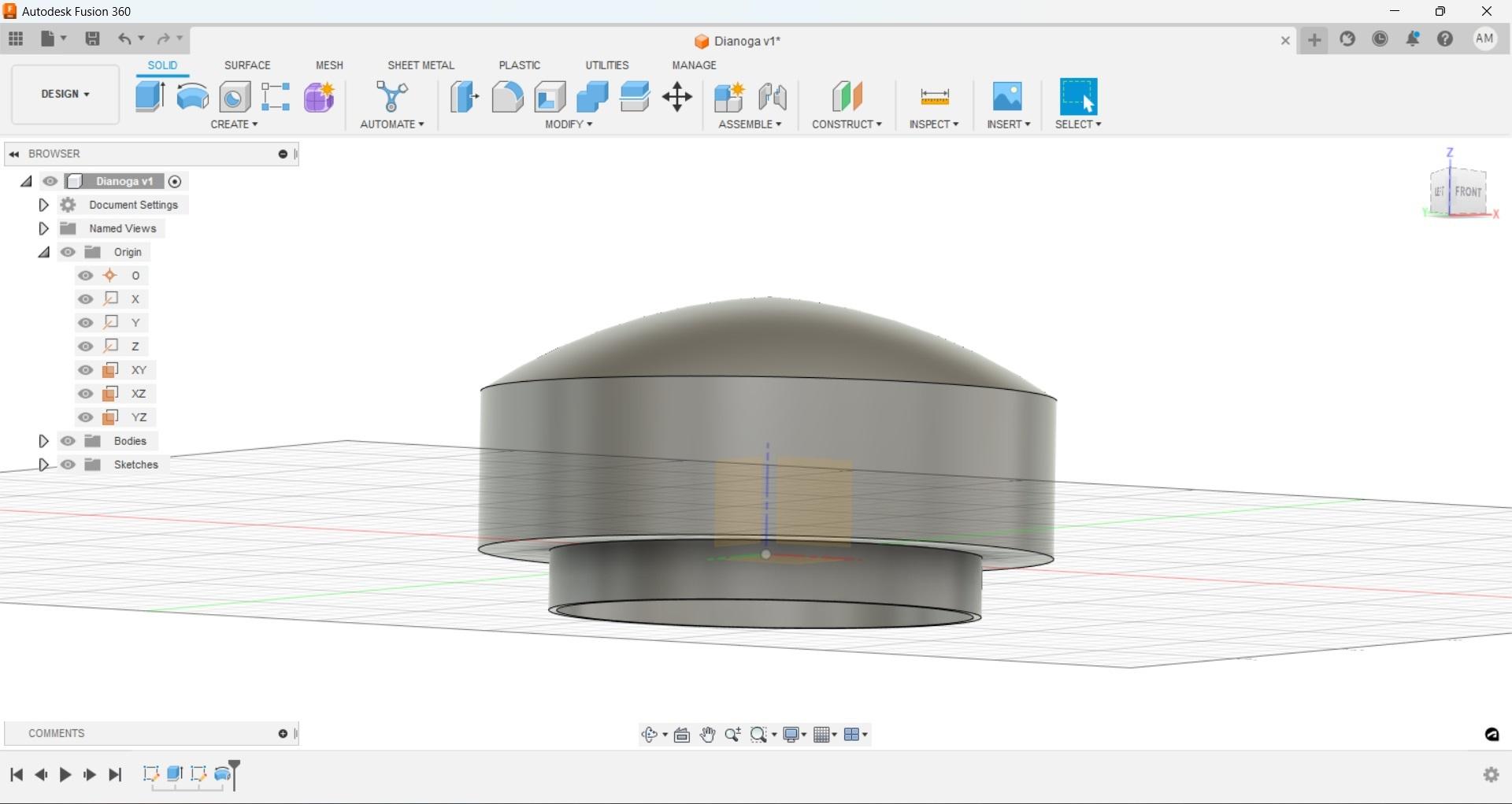
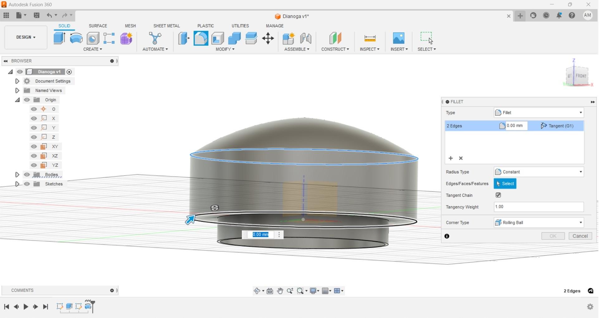
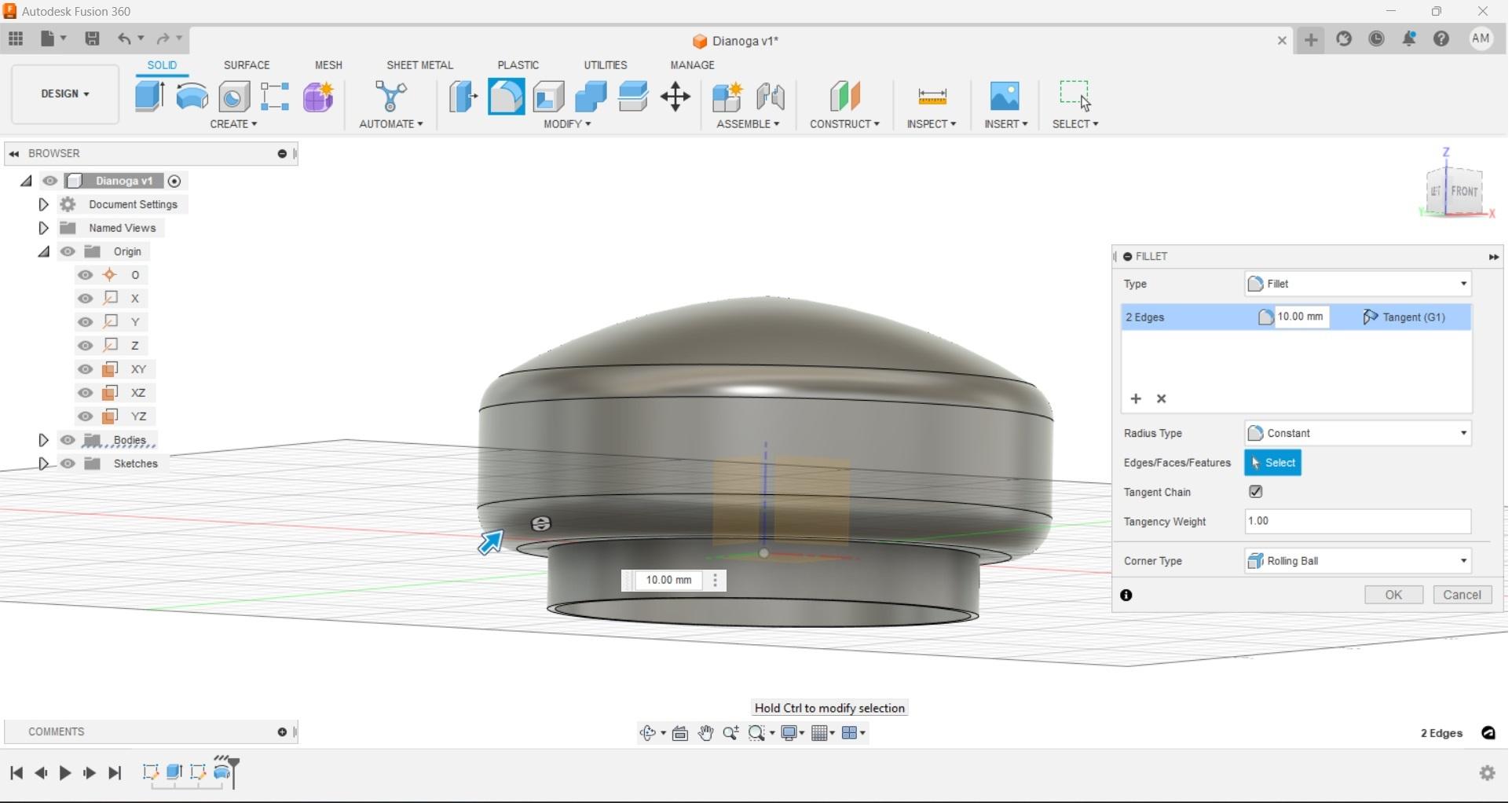
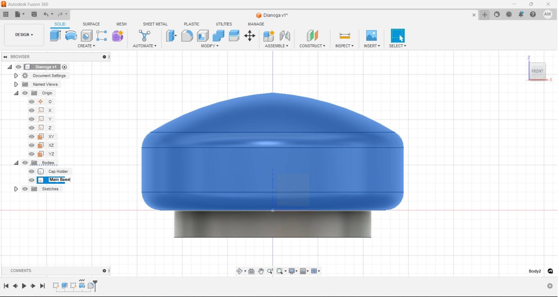
Having used the origin point as our center for our circle, and an origin plane for its starting face our life will be a little easier when we create the main body. Keeping the base simple allows us to use the "rotate" function to make a nice smooth round base that will be the main floating section of our design.
Since we are going to work with a complete 360-degree rotation either the 'XZ' or 'YZ' origin planes will work. I used 'XZ' but once we finish the step it will make more sense why either option would work. Create a new sketch on the desired work plane.
In order to ensure we end up with a part that is attached to our holding ring, project the geometry of the top most line using the project function as shown. It can be a little hard to see if anything has actually happened so change the viewport setting to wireframe.
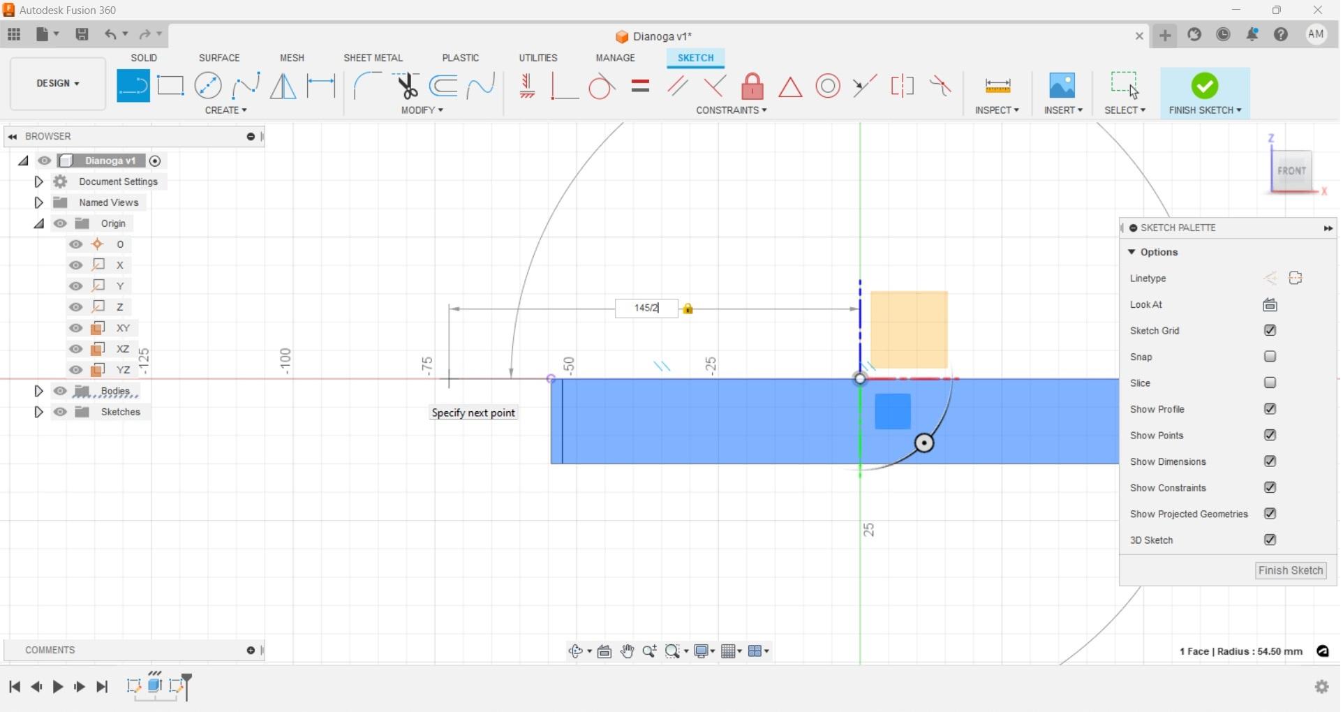
Keep in mind when using the rotate function you only need half of your object, even though we used a rough diameter measurement we can easily input this into our bottom line dimension as "145/2" Fusion will do the math and give us our radius, which is great since it reduces the chances of using a calculator and incorrectly inputting or translating a dimension.
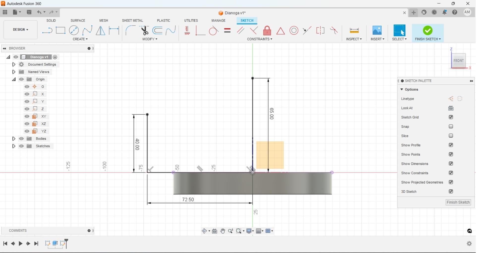
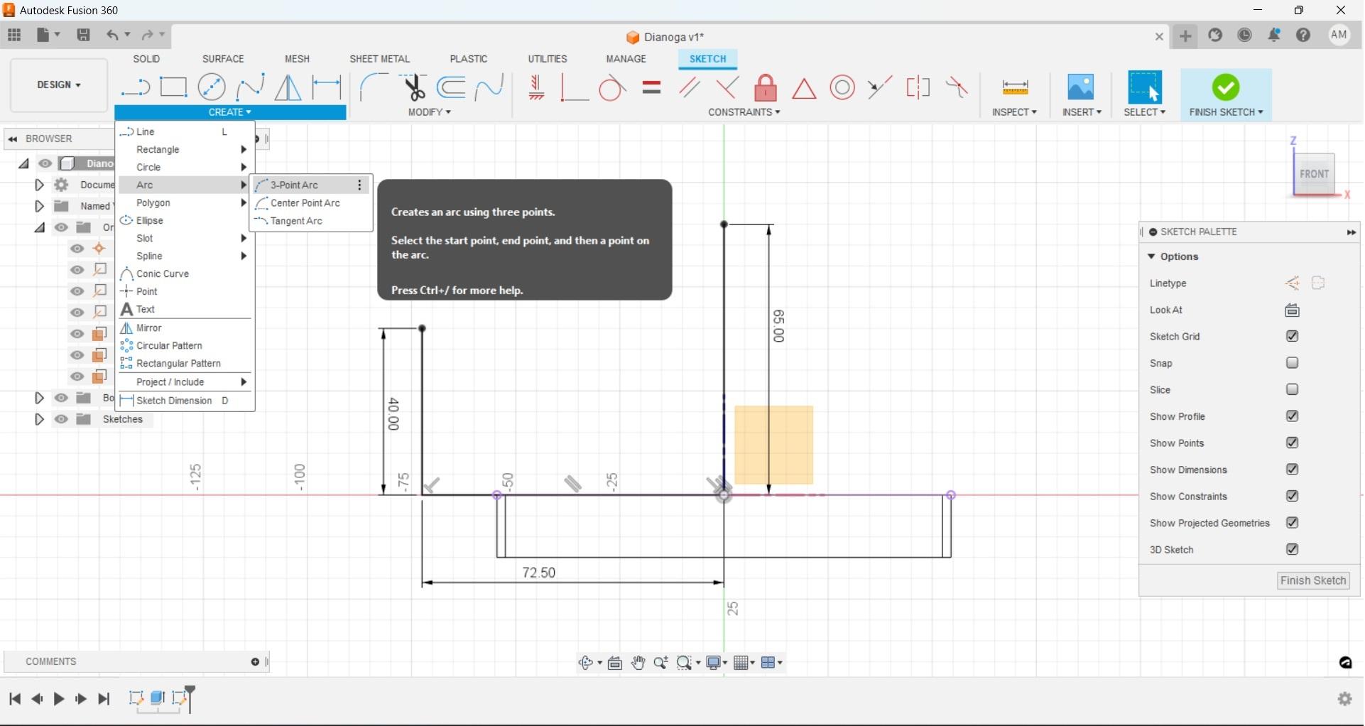
Add the two vertical lines with the rough measurements, then use the '3-point arc' tool to create a nice top that will slope down toward the outside. Select the end point of one vertical line, then the other, then select a third point that gets the desired shape.
Finish the sketch then use the rotate tool. While we could use the 'join' selection but for now use the 'new body' from the rotate menu drop down. If we used the 'join' function this would automatically connect this new rotation to our previously extruded ring, while there is nothing wrong with using that function we are going to use another feature called 'combine' to make a single solid part after we have completed our other components later in this tutorial. This would also be a good point to turn the viewport back to 'shaded with lines' so we can better see what is going on with our physical parts.
With our rotation complete we should now have what looks like a pretty good base for a chlorine float, but we can church it up a little bit by using the 'fillet' command to get those edges to not be sharp. Since we are not using an engineering drawing or making anything that needs to interact mechanically with another object you can input whatever dimension looks best for your fillet. Select the top and bottom edges and set your fillet dimension, I used 10mm, but again this is purely aesthetic and not functional
Fusion Eye
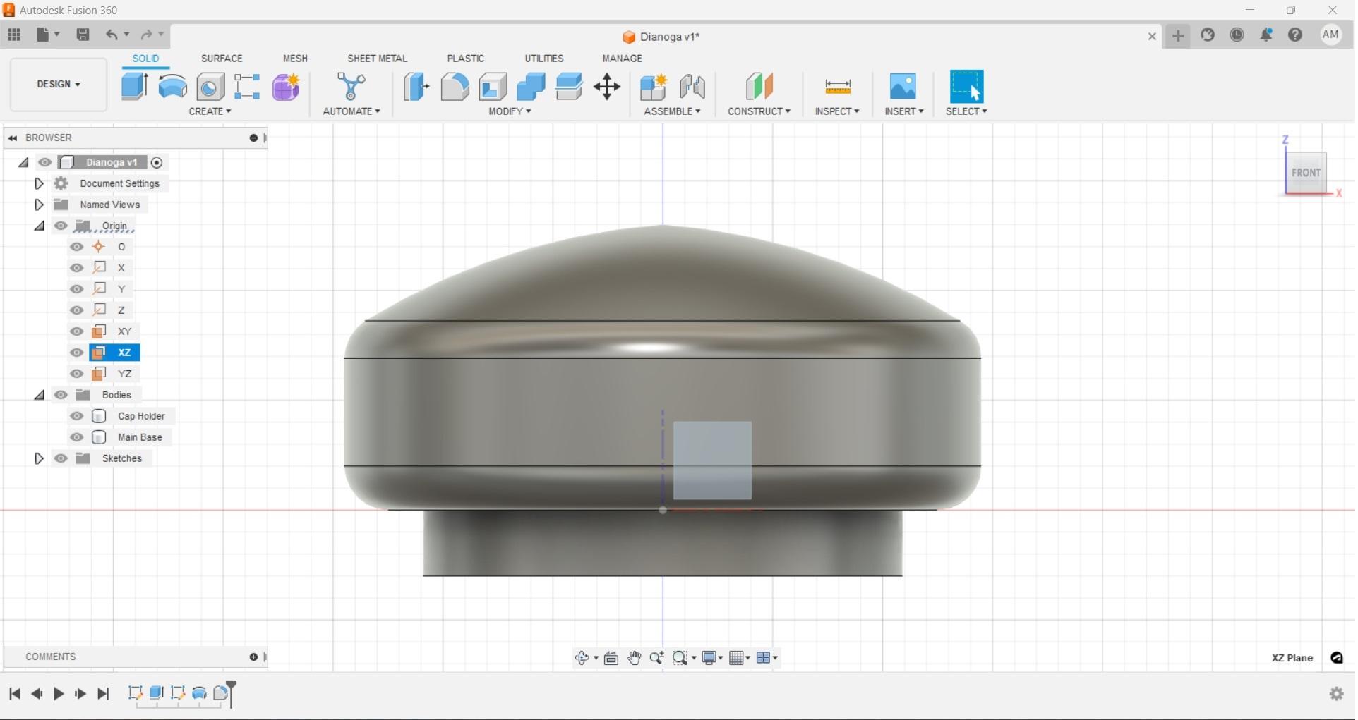
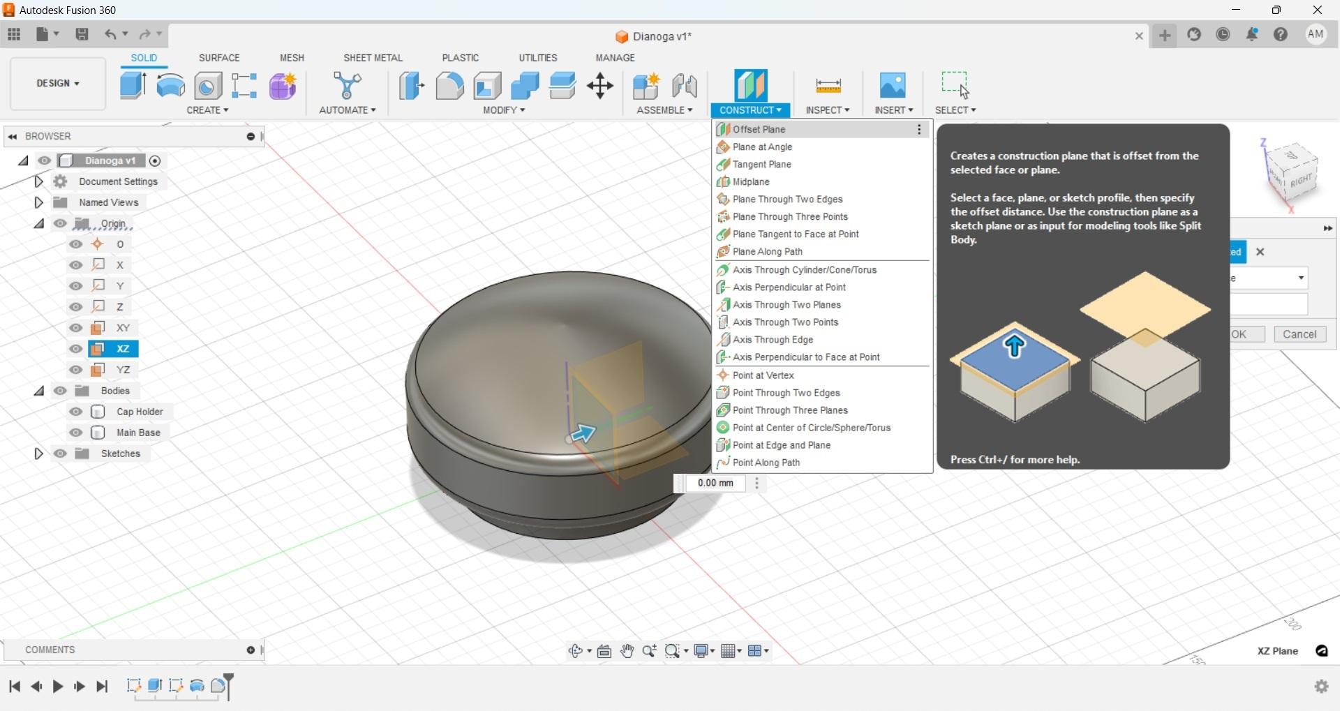
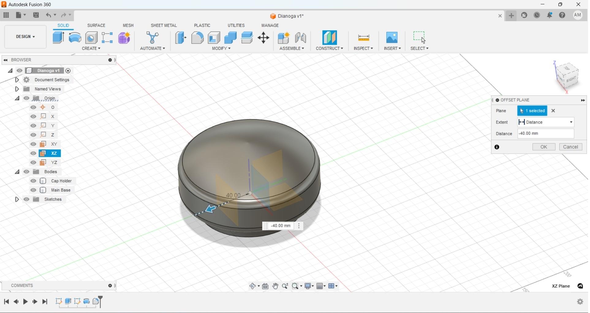
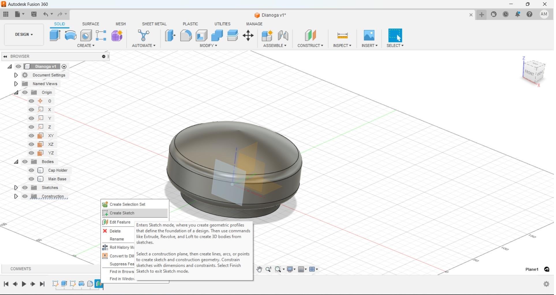
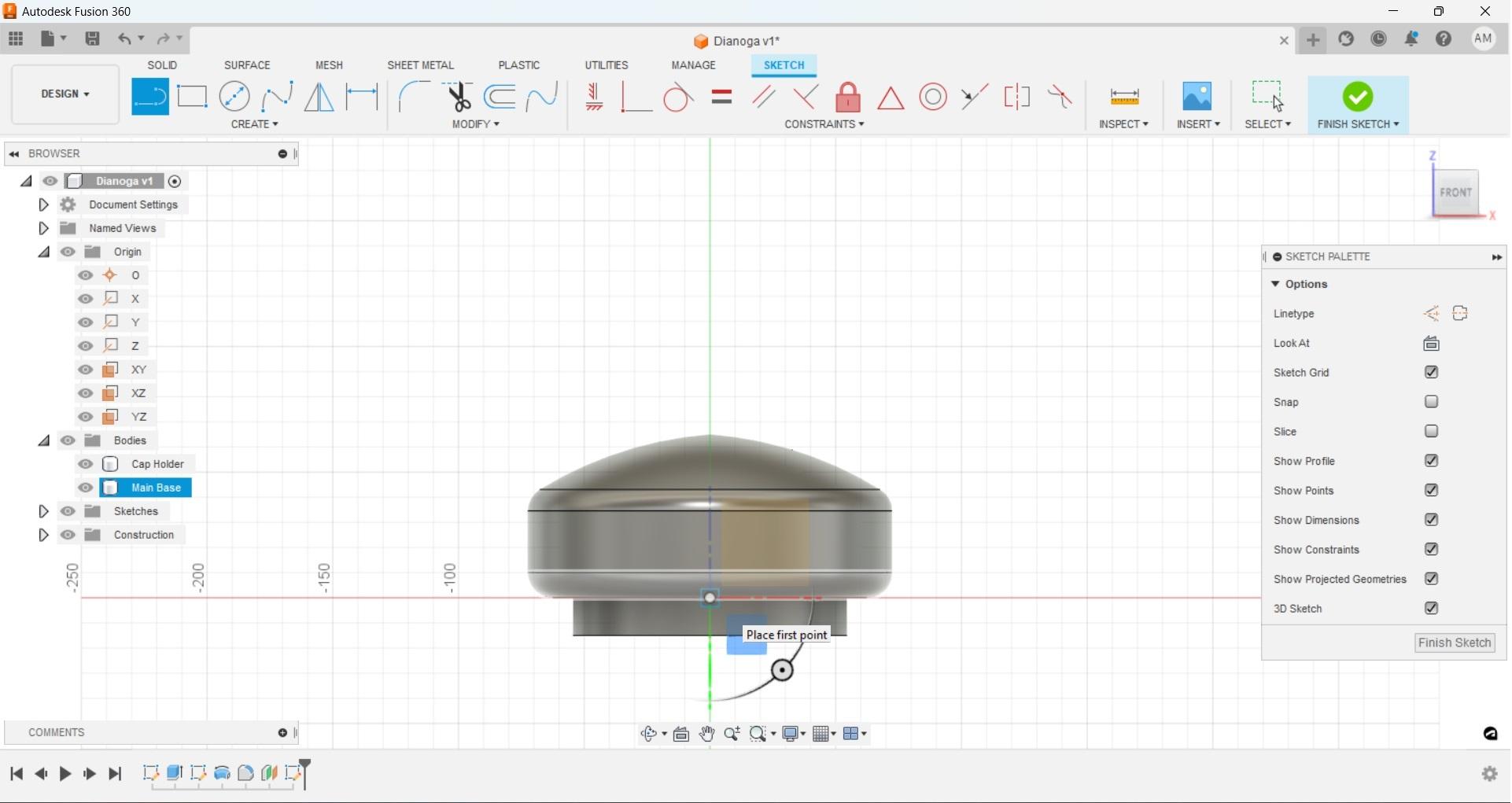
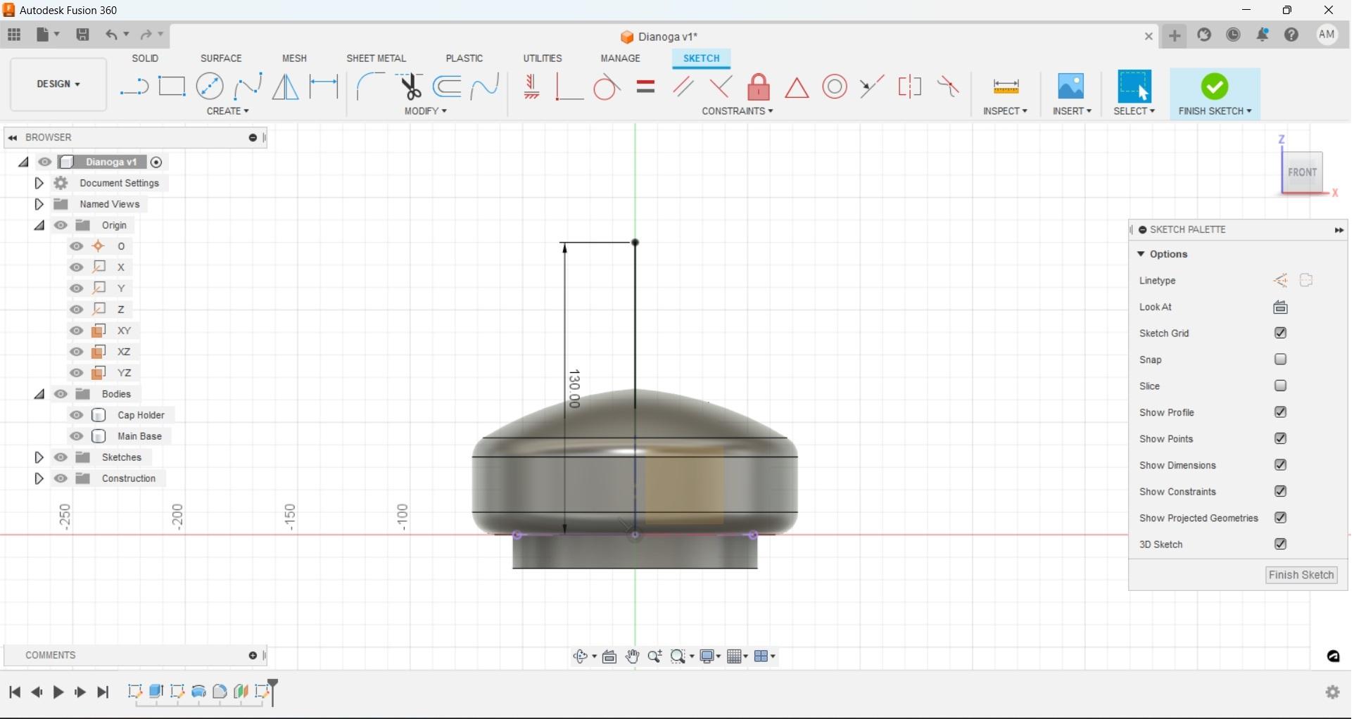
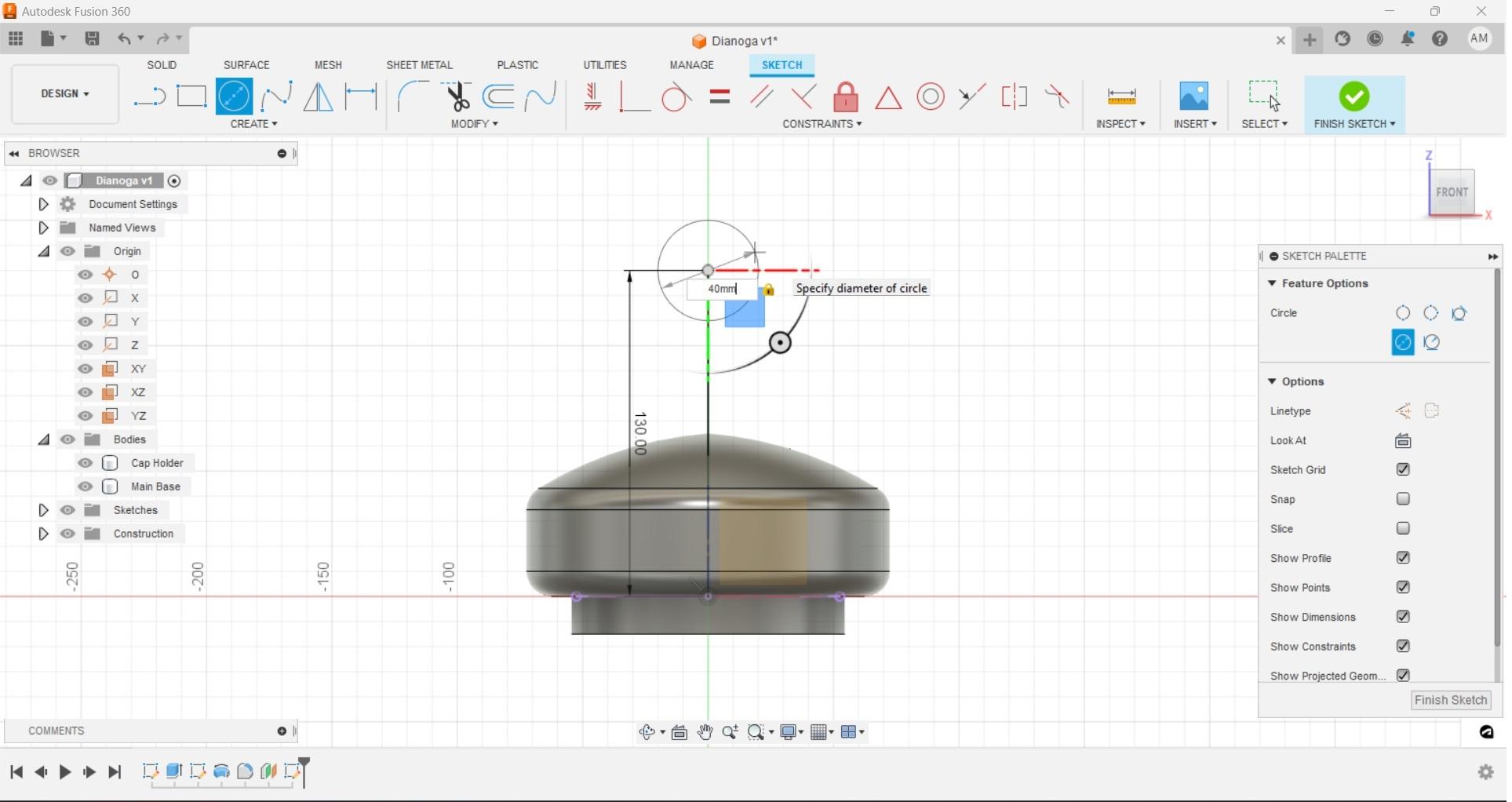
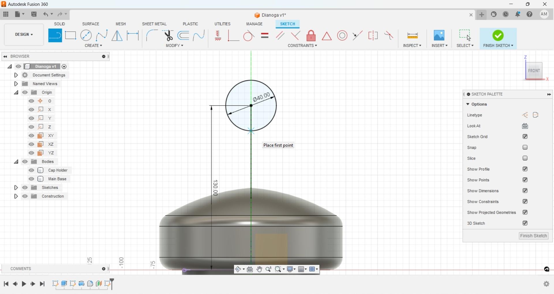
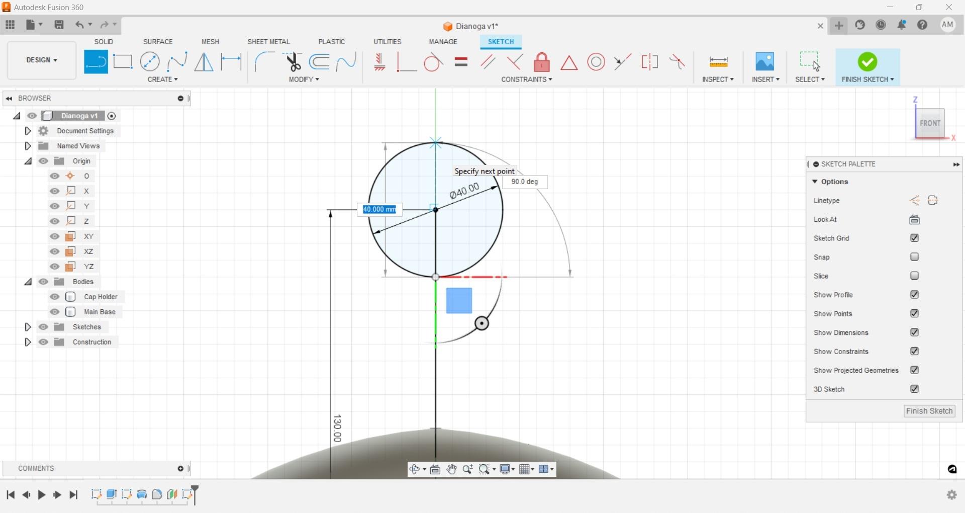
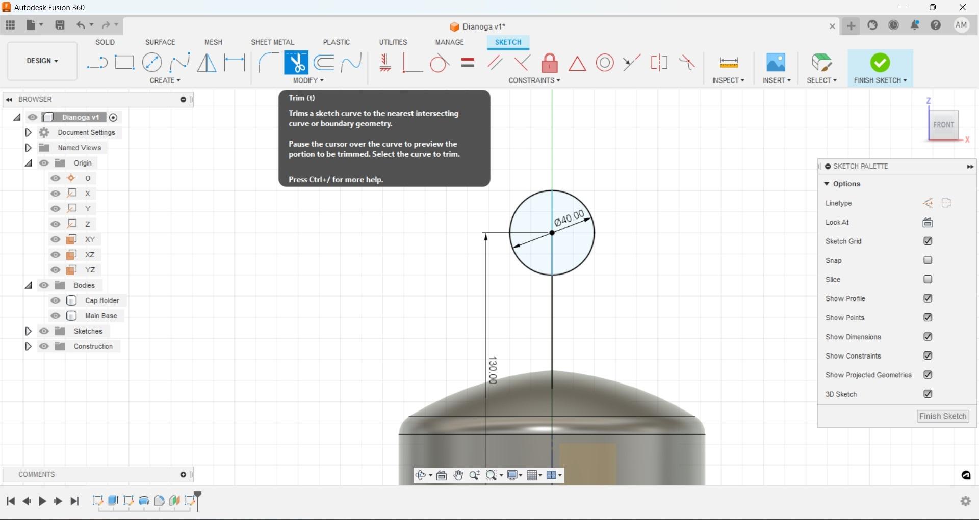
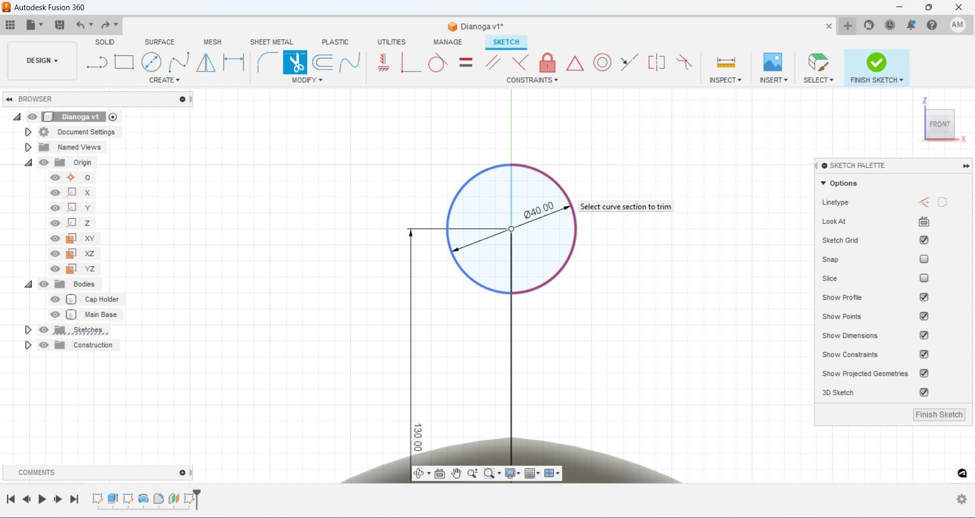
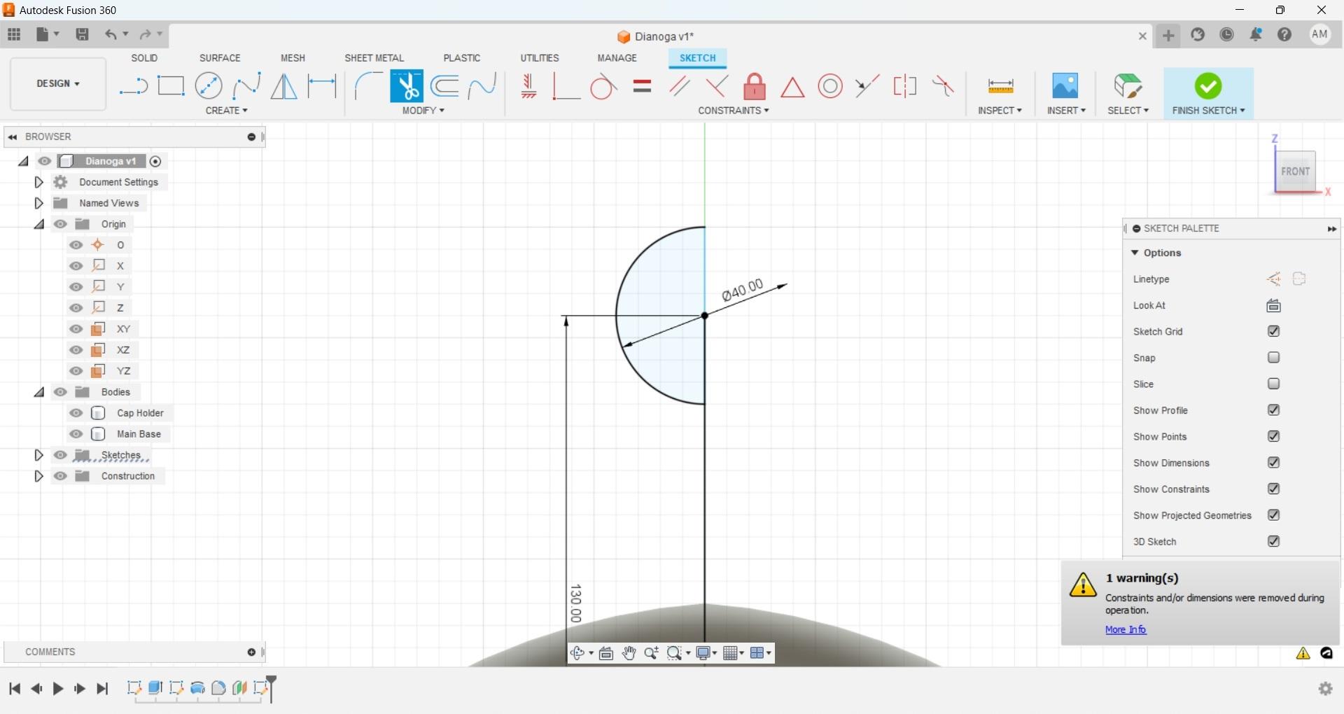
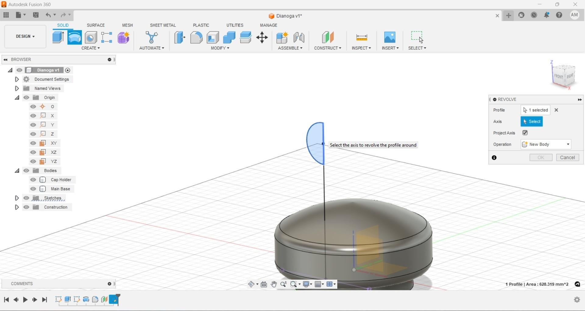
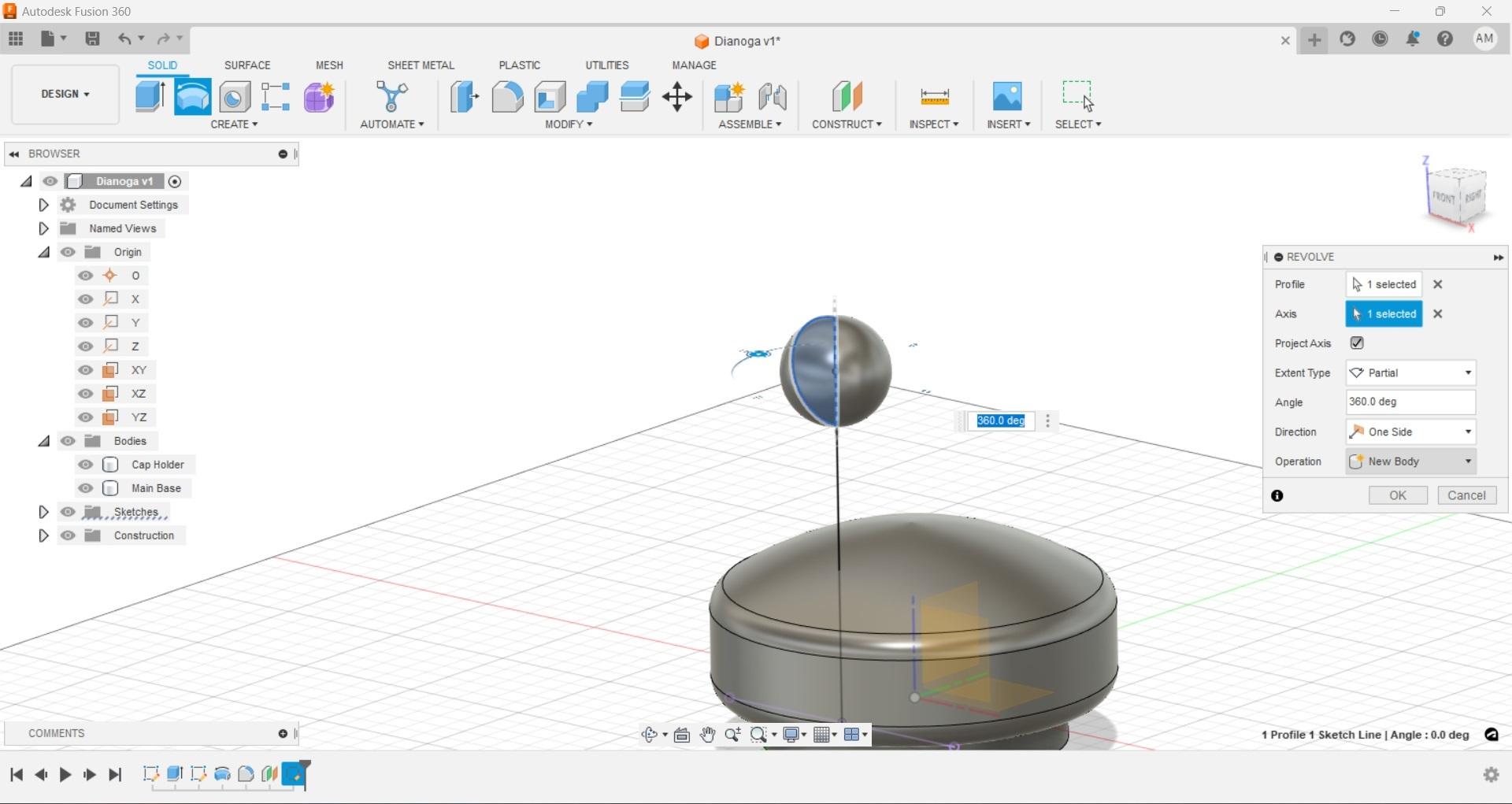
With the base in order it's time to get an 'eye' so we can match our next parts to it. The eye we are referencing sits a little forward on the body so offset a work plane from the 'XZ' axis as shown and create a new sketch. I went with -40mm, remember negative because we are moving forward on the Y axis toward the front.
Now we are looking at the float from the front, to keep things uniform use the origin point as the start of a new vertical line and make it about 130mm. From there we can create a circle with its center on that end point, then create another line to cut that circle in half vertically.
Next use the trim tool to remove one half of the circle. Finish this sketch and then rotate the half circle we just created around its center axis to create a sphere.
Fusion Form Neck
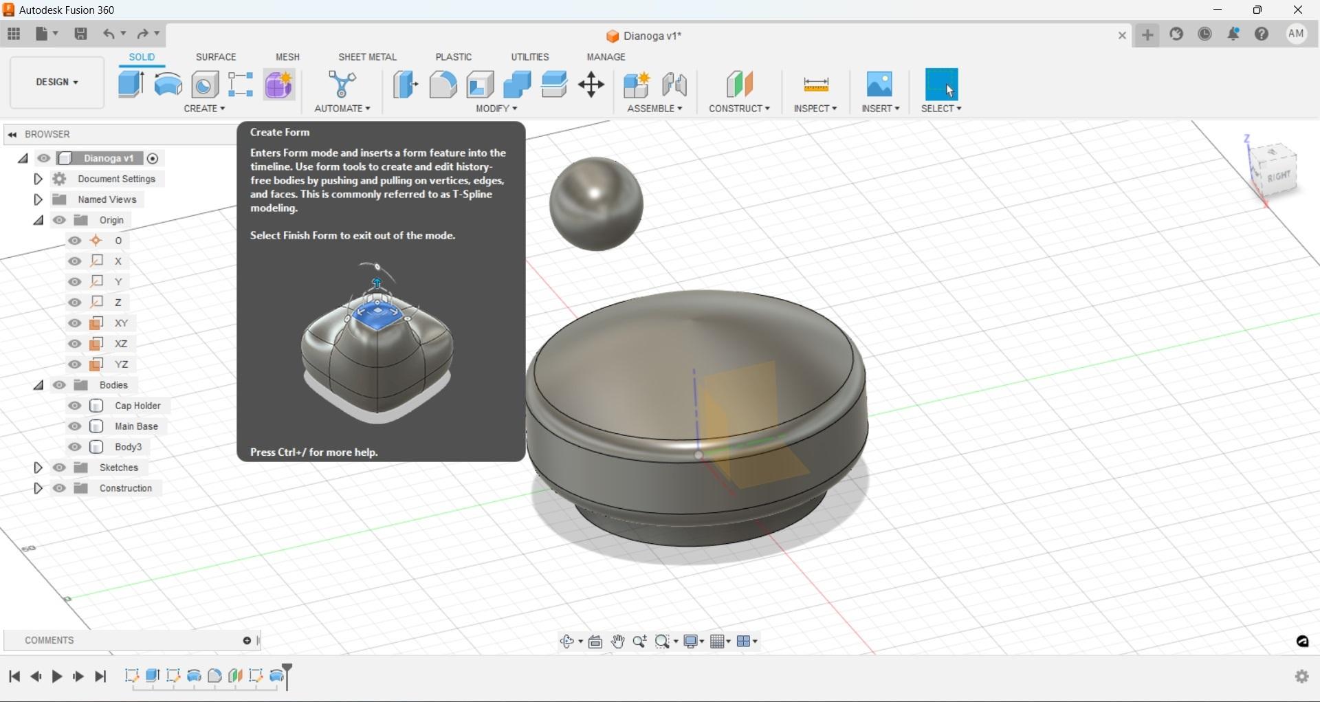
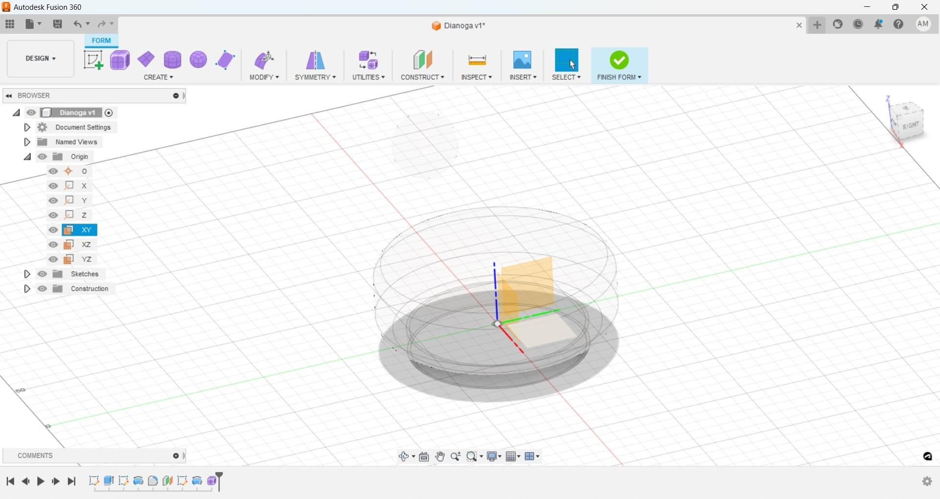
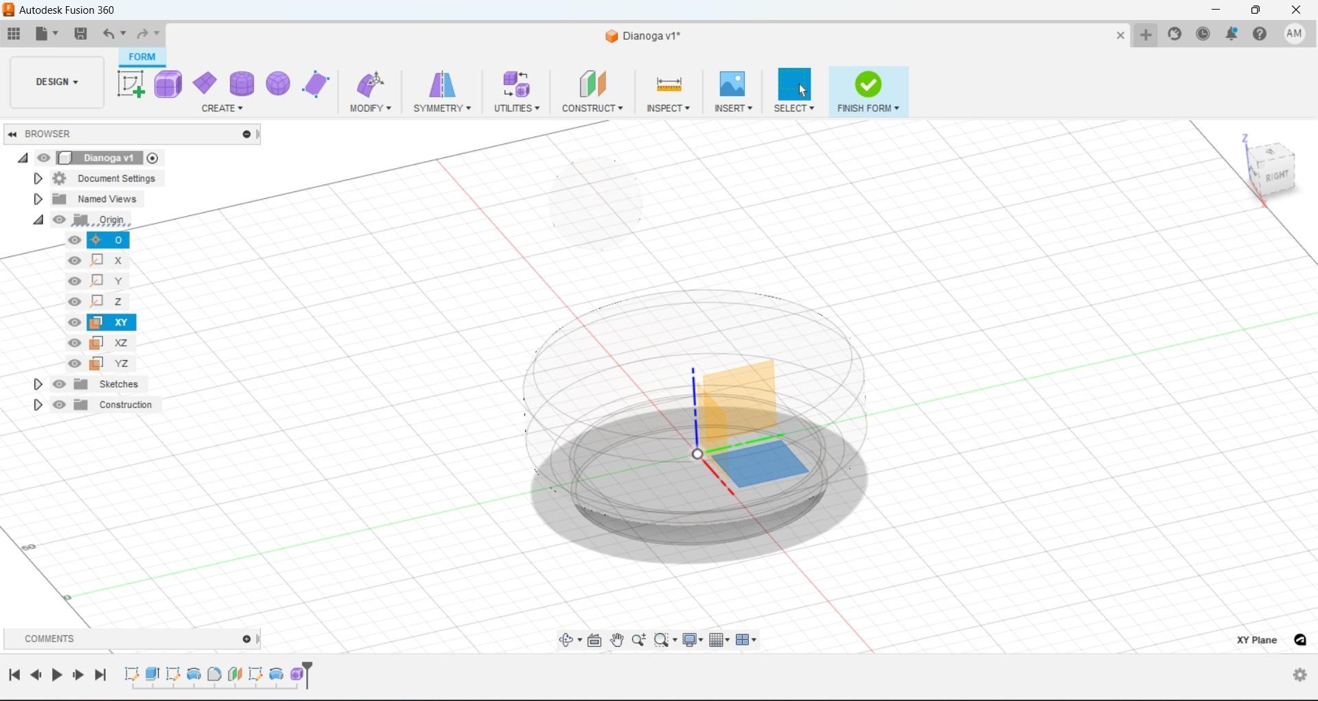
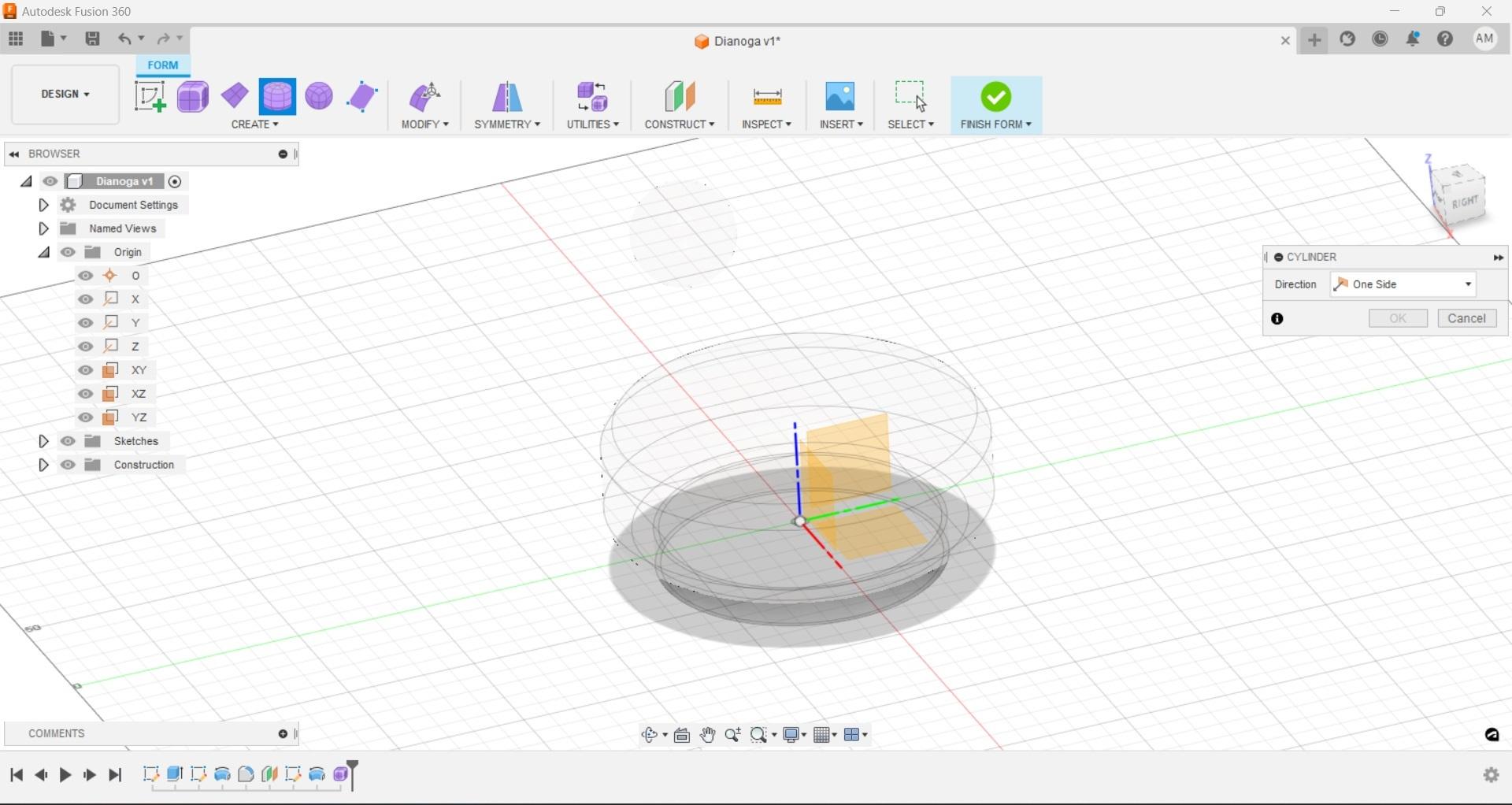
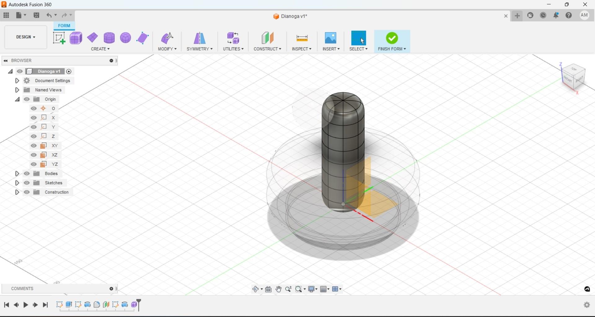
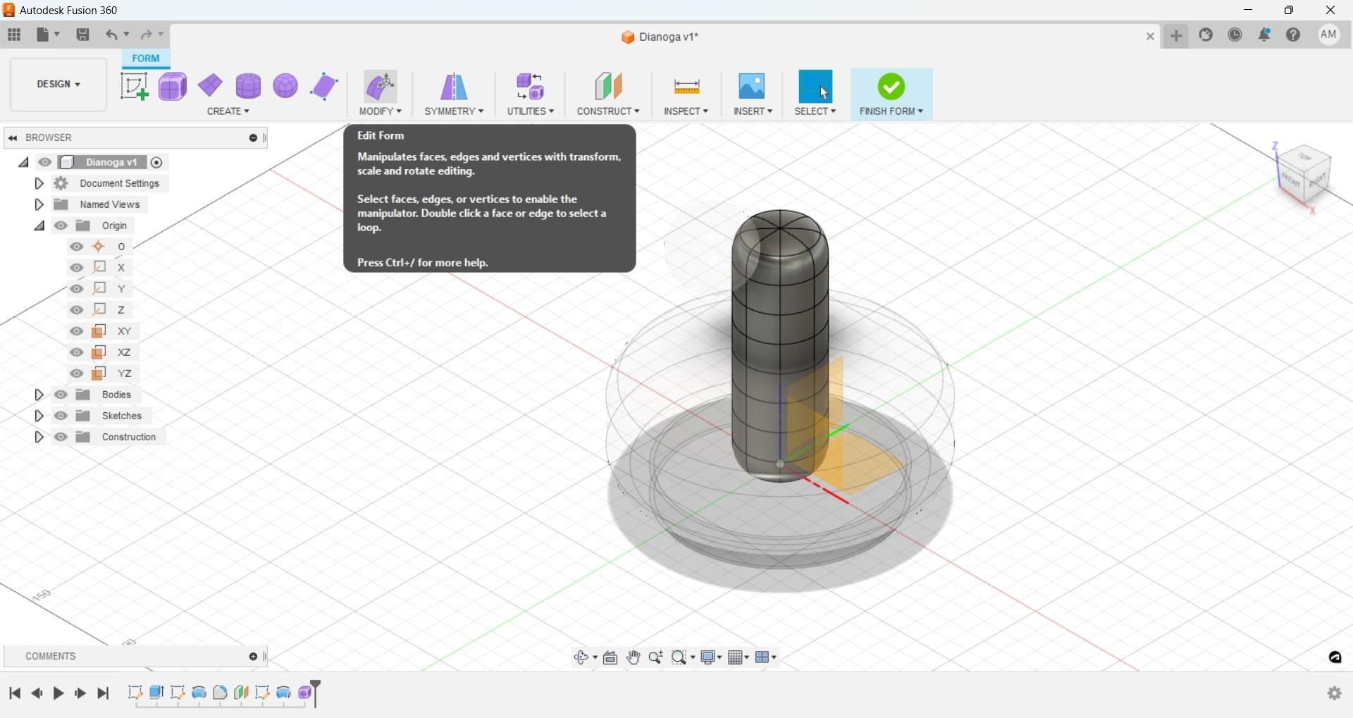
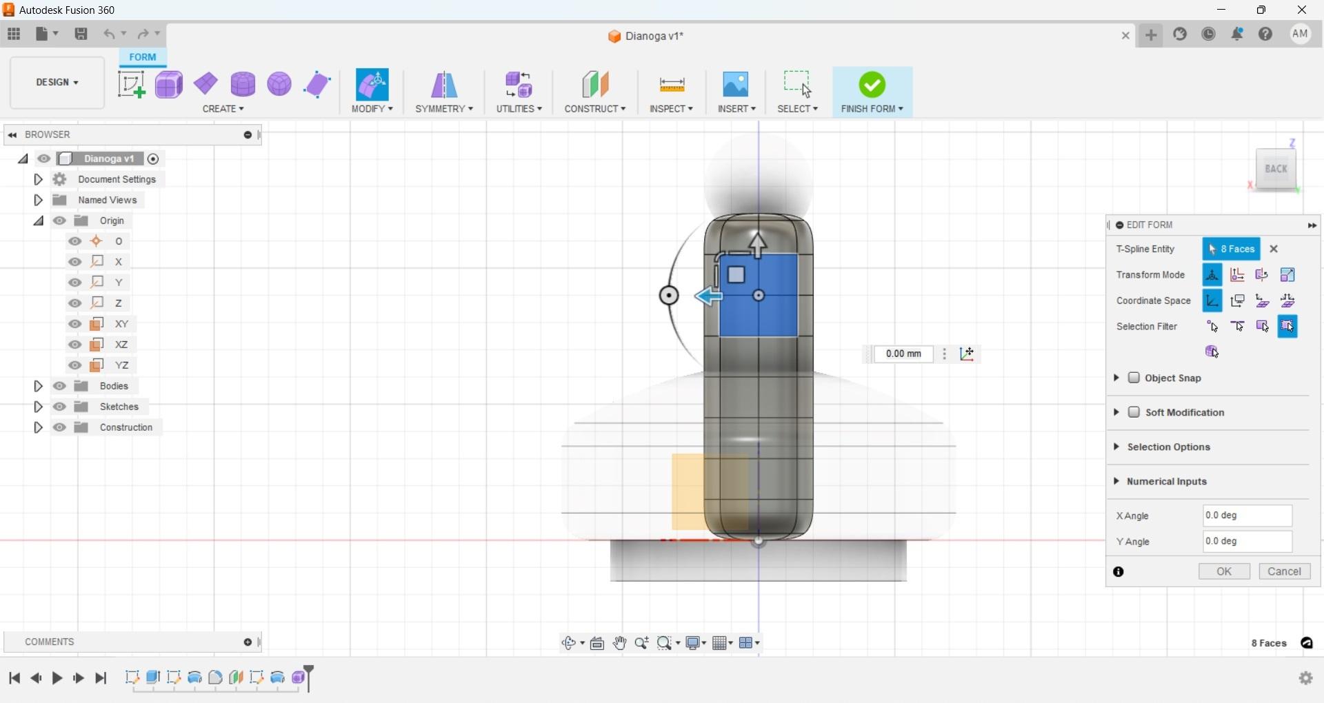
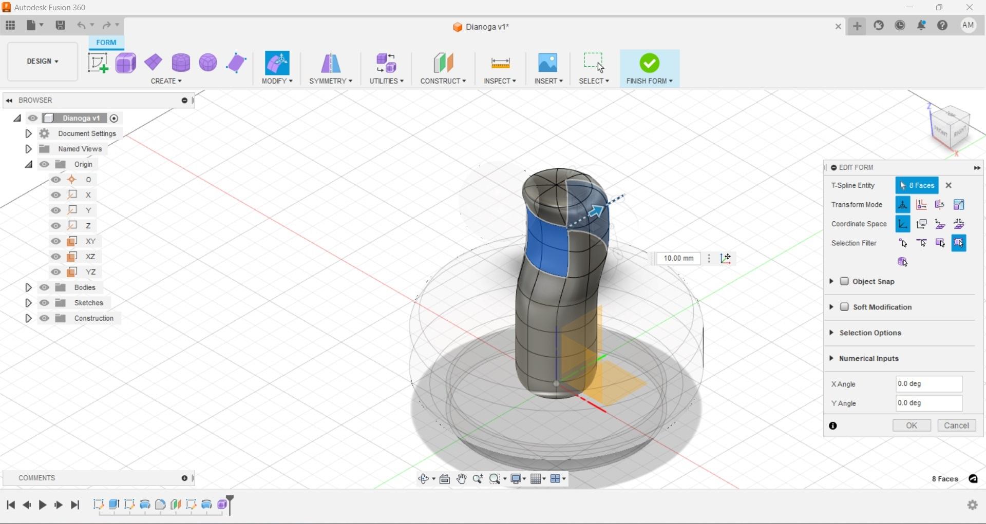
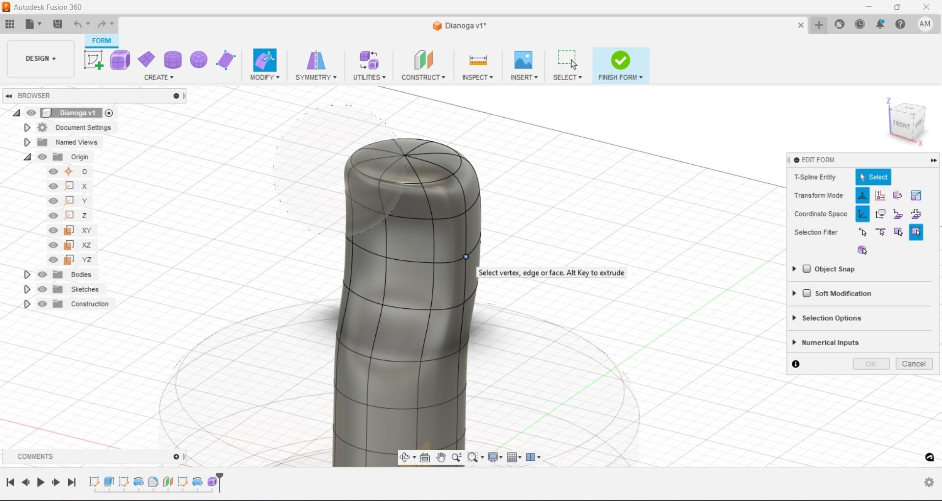
At this point all that work has been CAD in the strictest sense, we take a 2-dimensional design and push/pull, rotate, etc that closed sketch into a 3d form. To form the remaining parts we will use the 'create-form' command and be working in the free form workspace.
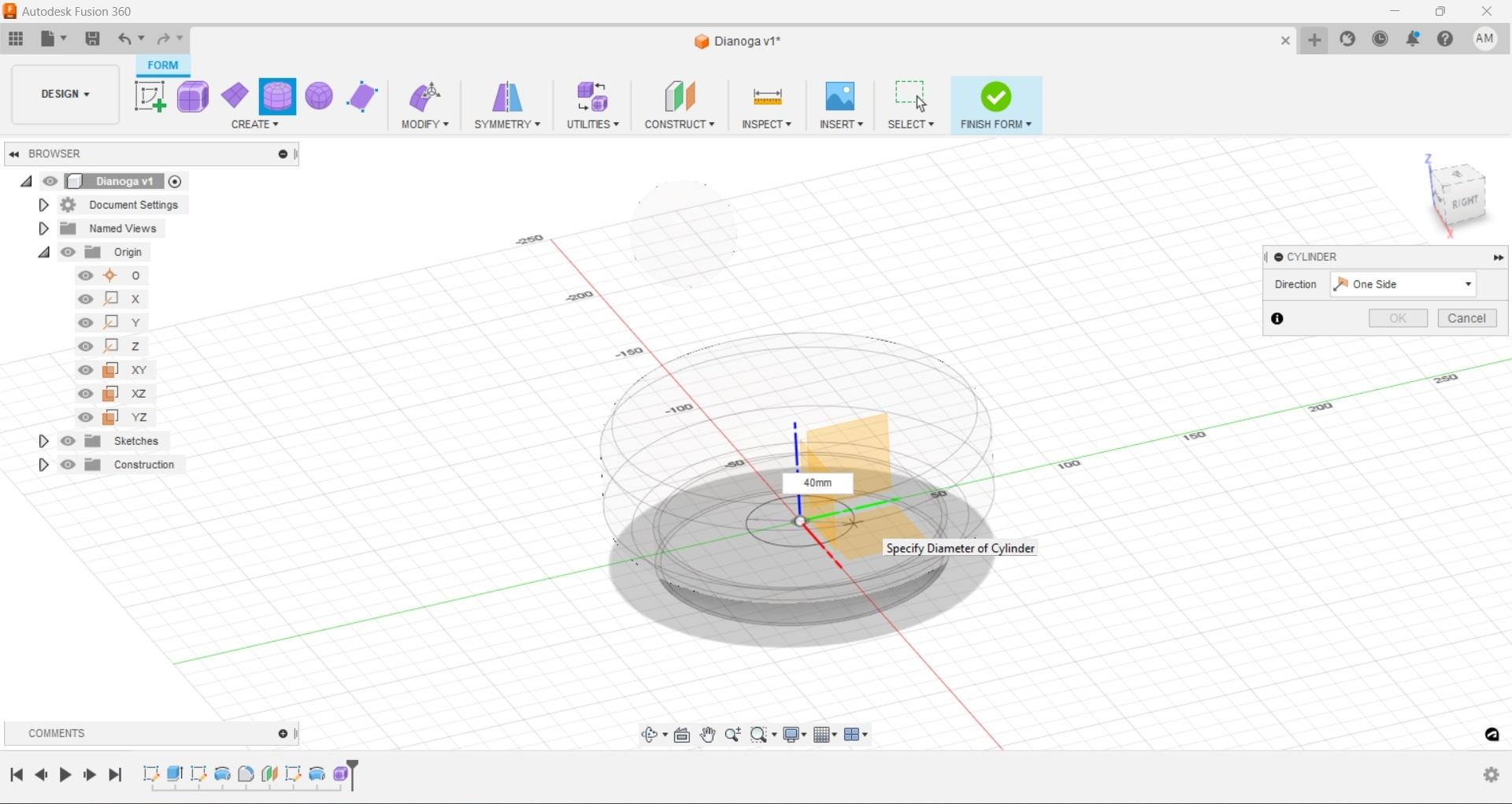
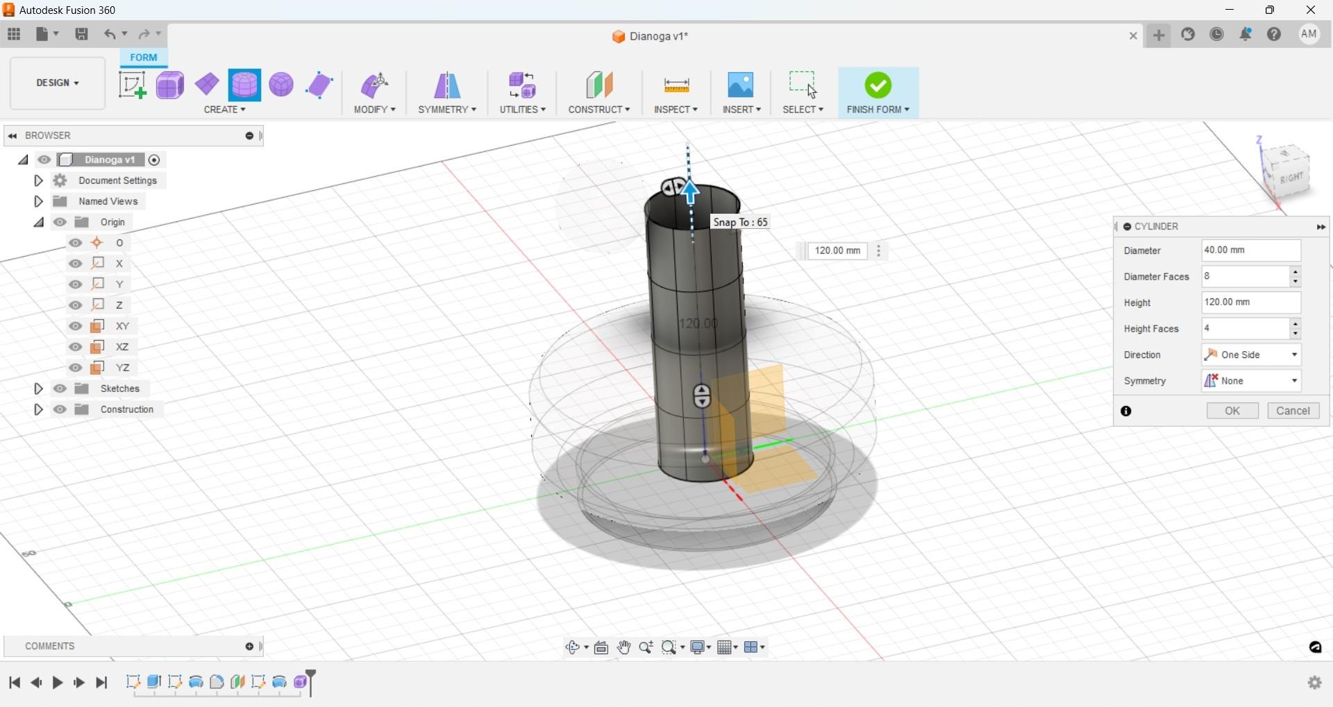
We can start with creating a neck for our creature. Now in the free form workspace we have new options, select the 'cylinder option' and again we will use the 'XY' plane and origin point as our start point. You will be asked for the diameter of the new cylinder prior to anything appearing, set the desired diameter, I chose 40mm. If you begin working and find it is not what you were looking for don't worry, you can set it again in the next dialog box.
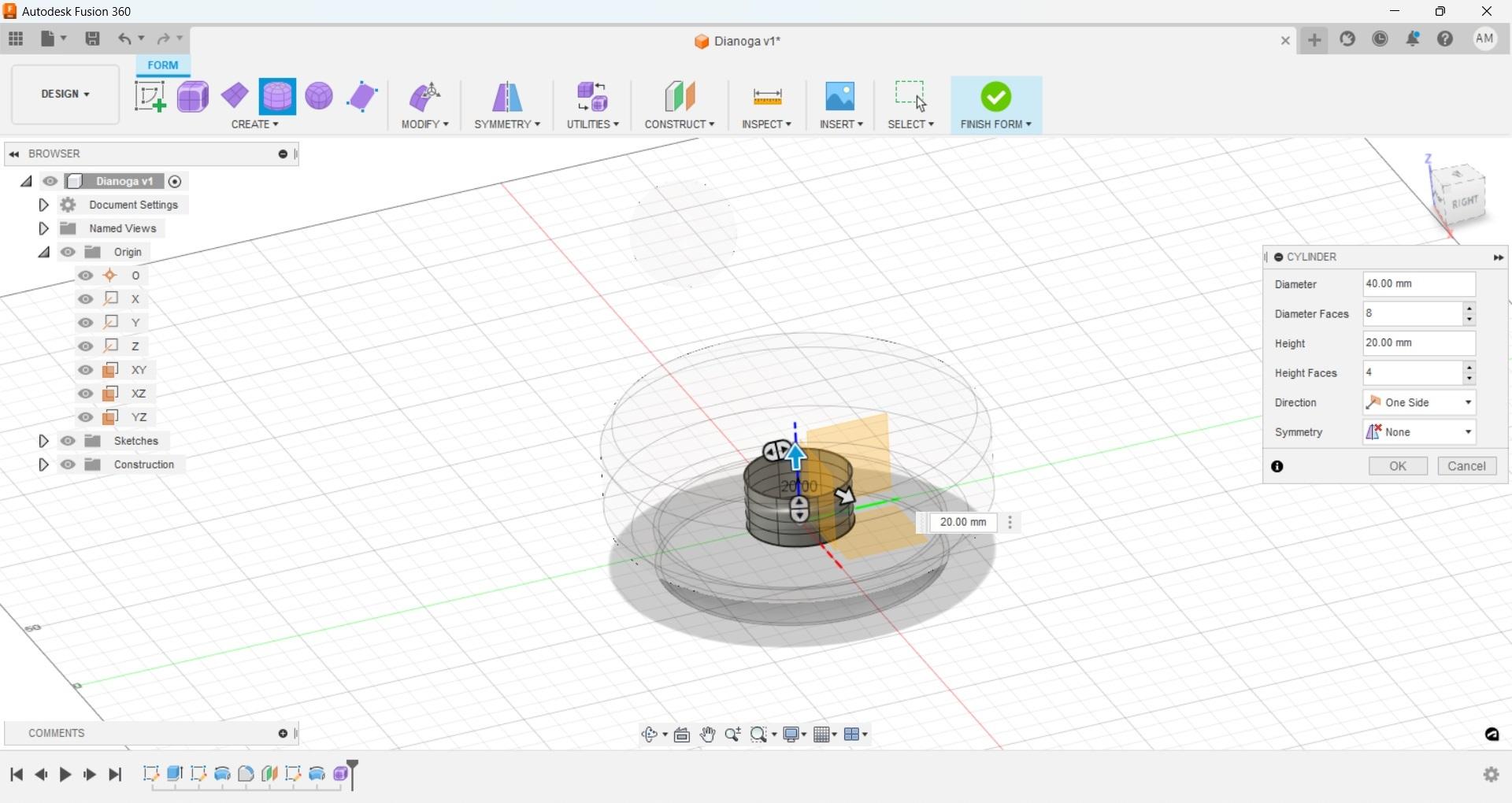
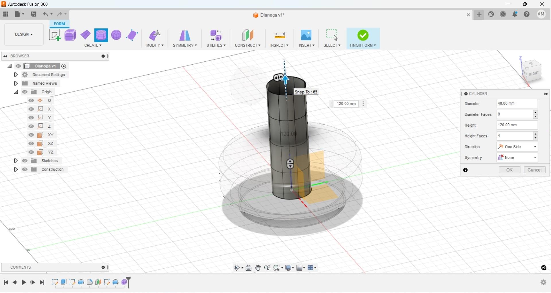
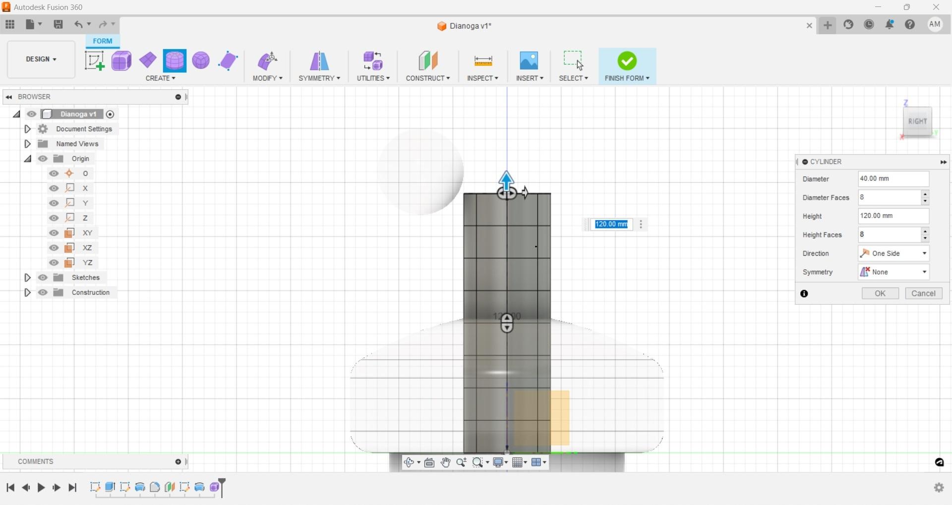
With the initial diameter set a new 'cylinder' dialog box should be open on your screen. The dimensions can be entered manually or we can drag the widget arrows in the appropriate direction to get our desired look. If snapping is on you may have difficulty dialing in where you want the cylinder to end, but if you get it in the ballpark you can then manually enter a dimension to get it more exact. To better line up our neck switch to the right-side view using the navigation box on the top right and adjusting where the neck will stop at using that and the very faint outline of the eye.
Before hitting ok increase the number of height faces so that there is more geometry to work with, I only went with eight, but you can increase to as many as you'd like, keep in mind though this can adversely affect system performance and you can always add cuts later so in this case more is good, too much is bad. When you're happy with the number of faces you have hit 'ok' this will complete the initial setup of the neck cylinder.
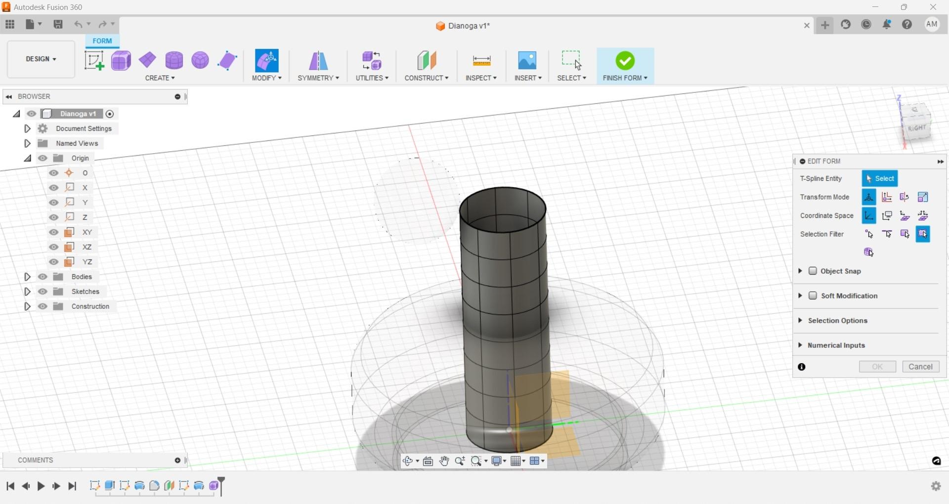
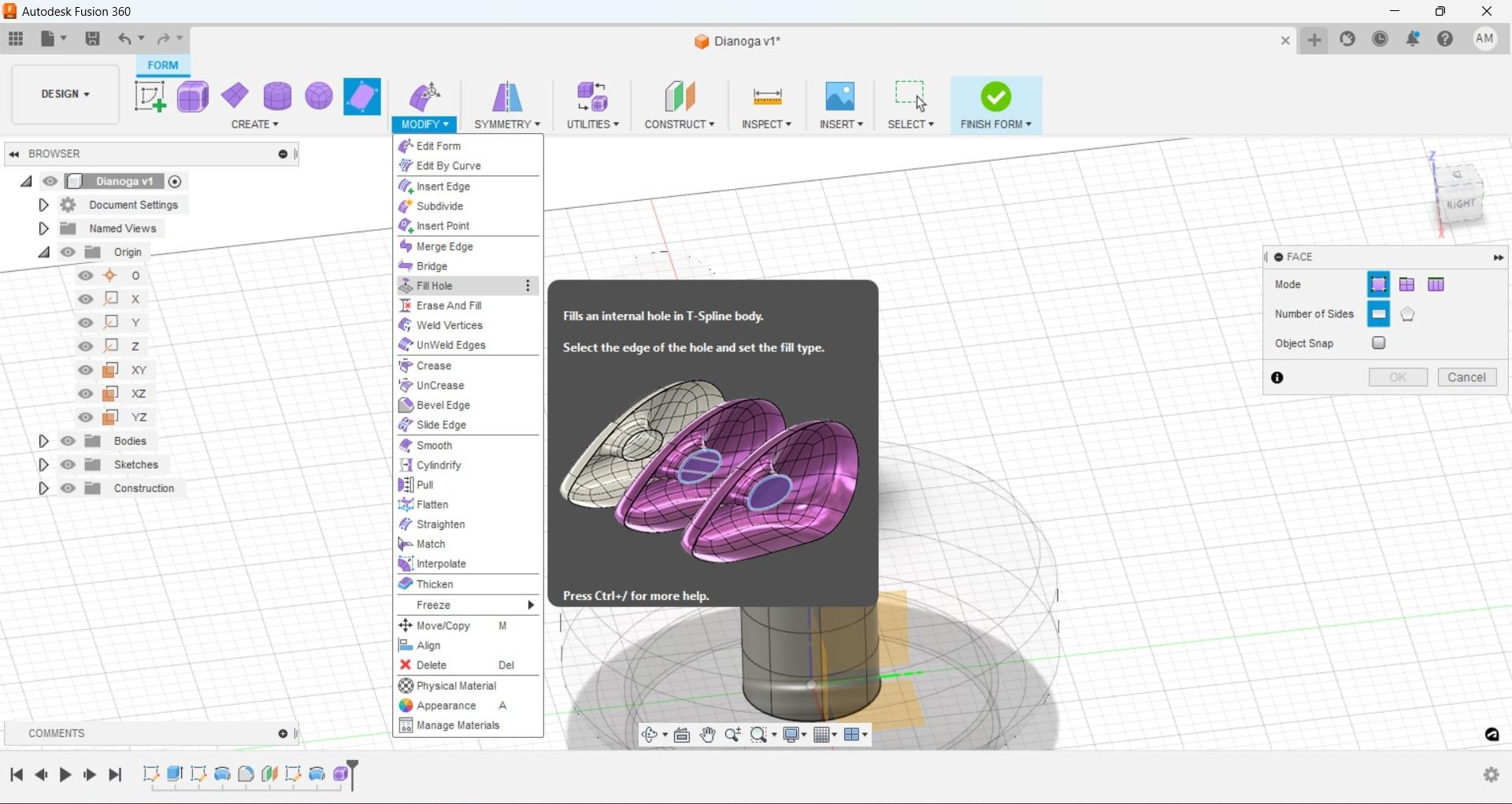
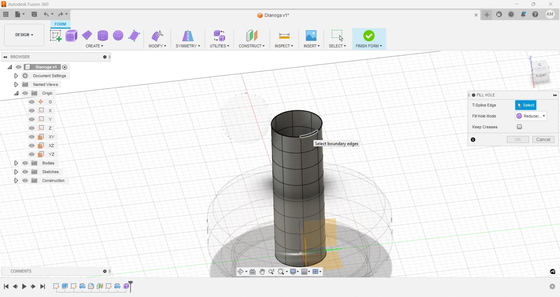
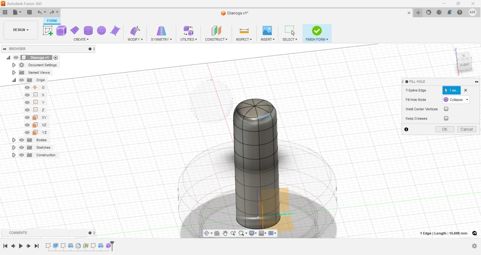
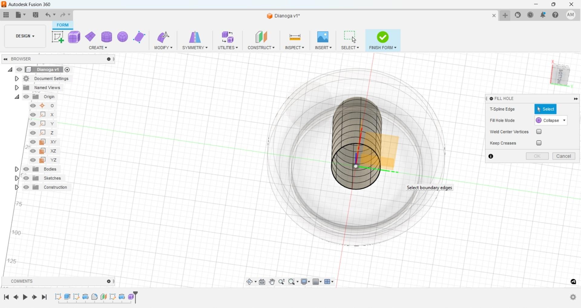
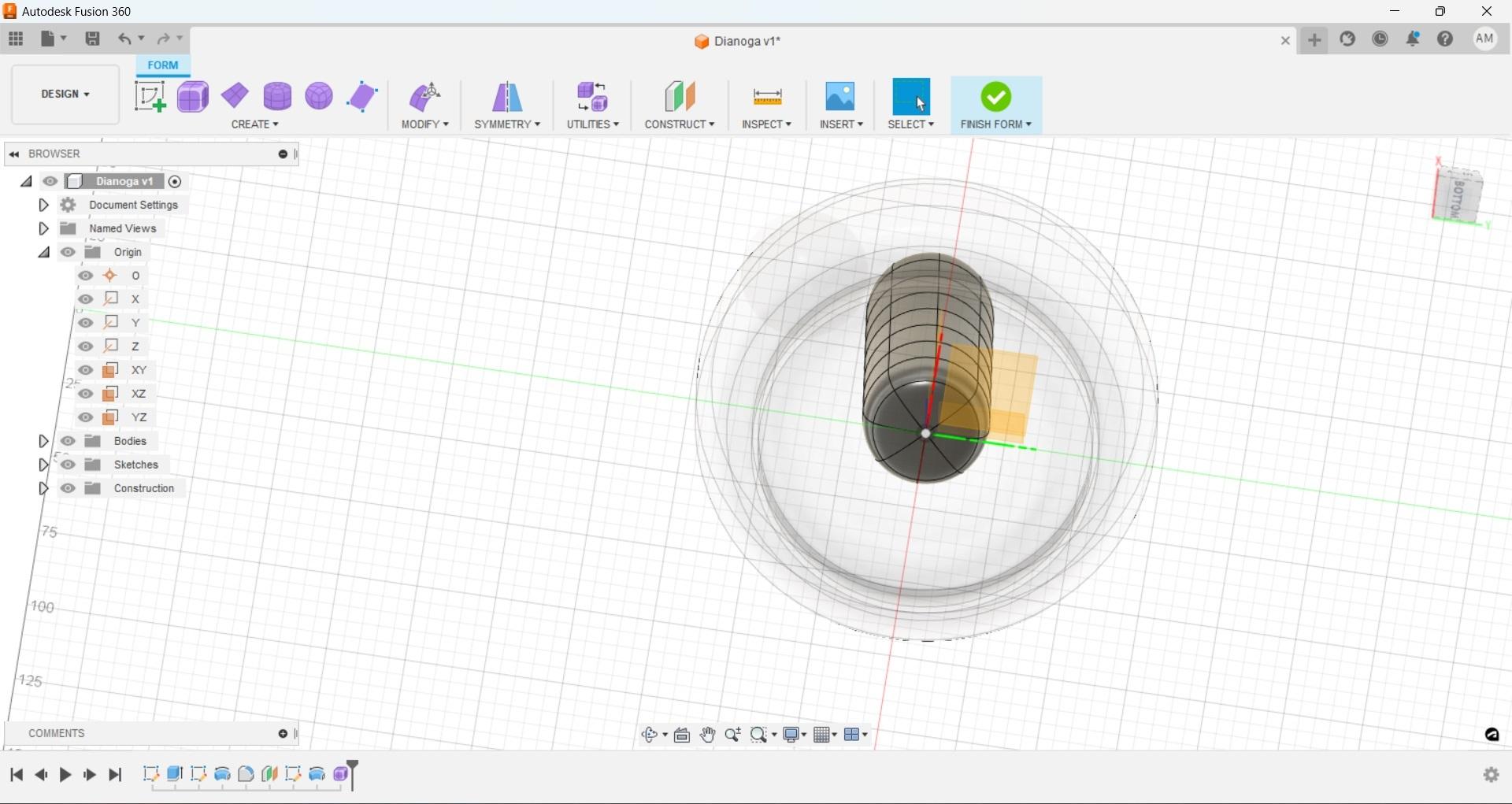
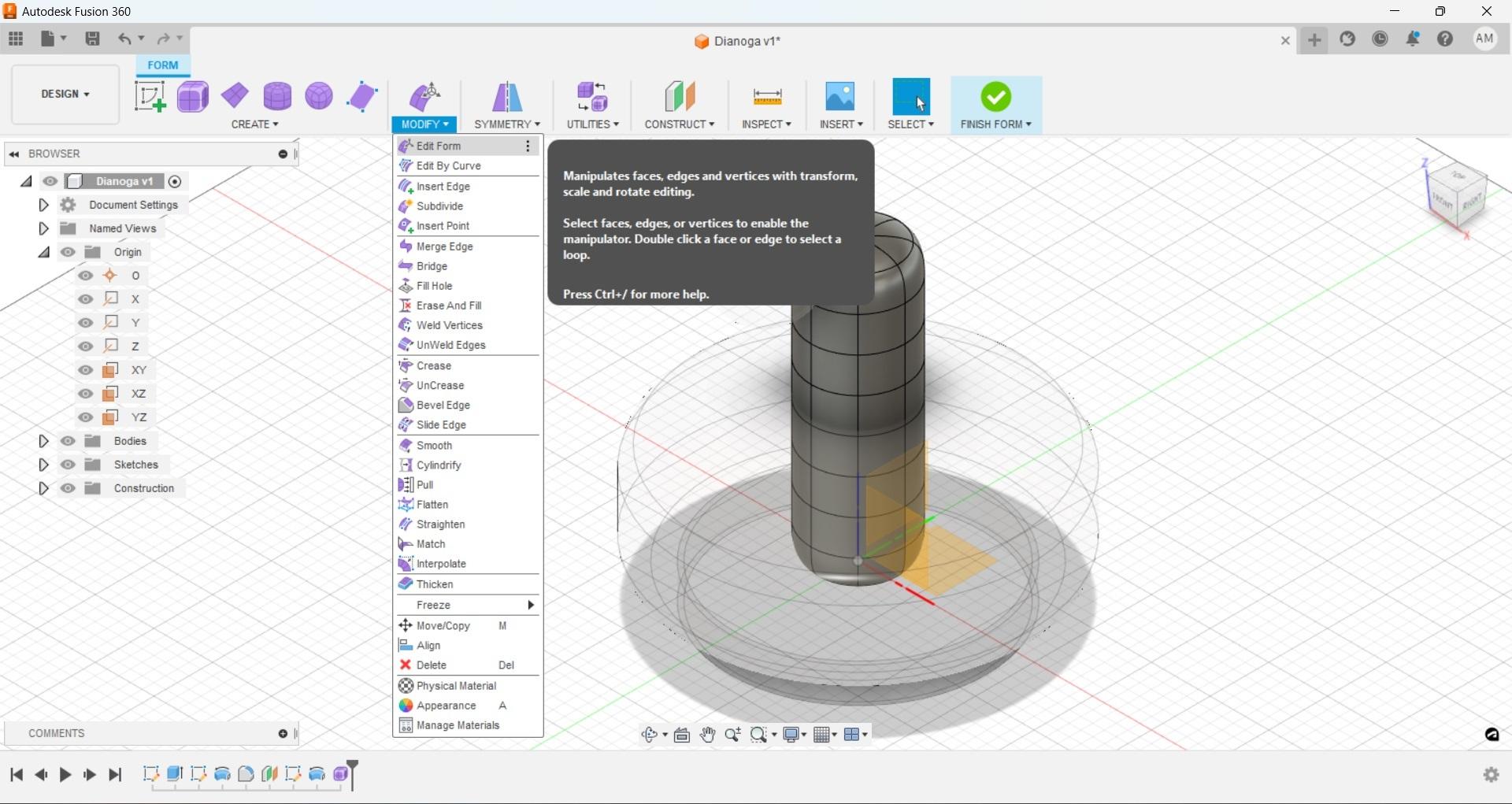
Before we continue with detailing the neck we need to cap the ends of the cylinder off otherwise we have an object with no volume when we try to combine with other solid objects. To do this you can select a line on one end and double click it to select that entire ring, then use the 'fill hole' command in the 'modify' drop down as shown. The default is simply a cap, so use the new dialog drop down to select 'collapse' and hit 'ok', do the same for the bottom of the cylinder.
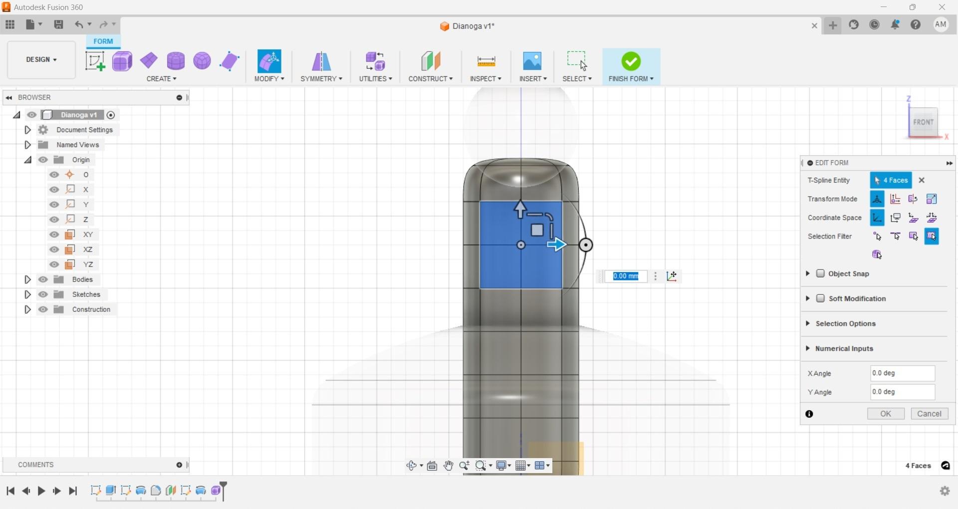
Great now we have a cylinder that we could have easily just extruded from a circle, yes, but now we can use the free form options to actually give this an organic look. We are going to keep the neck fairly simple and only use the 'modify/edit form' function. Select a group of faces on the front and back sections of the neck. Select 'edit form' from the 'modify' drop down, now we should have some widgets and a dialog box to manipulate the selected faces.
Let's just give a nice curve to the neck by moving all of our selected faces back on the 'Y' axis. Since we have an equal number of front and back faces selected the entire form will move back and look relatively uniform.
Fusion Form Eye Socket
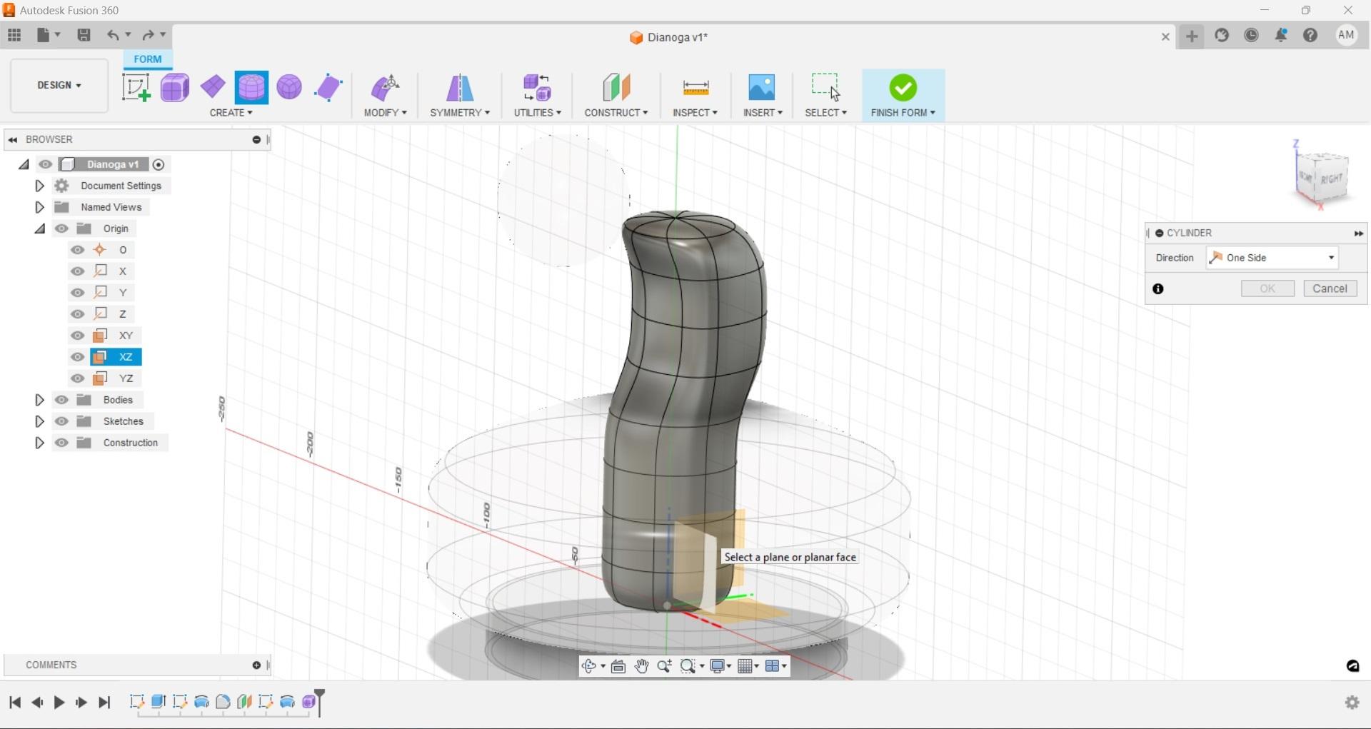
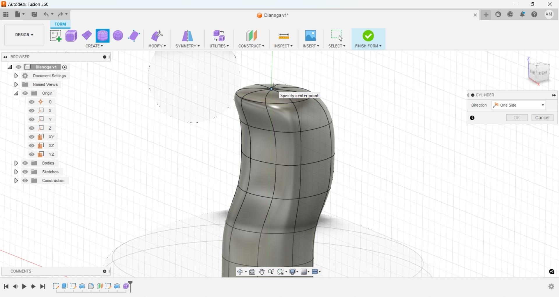
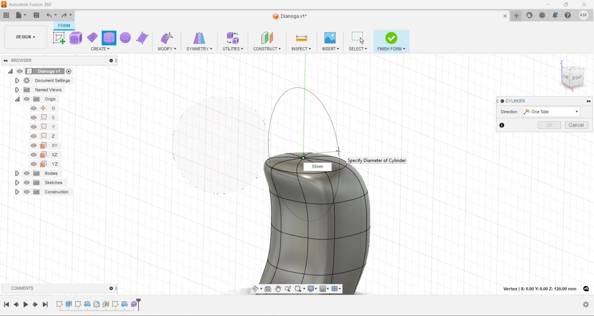
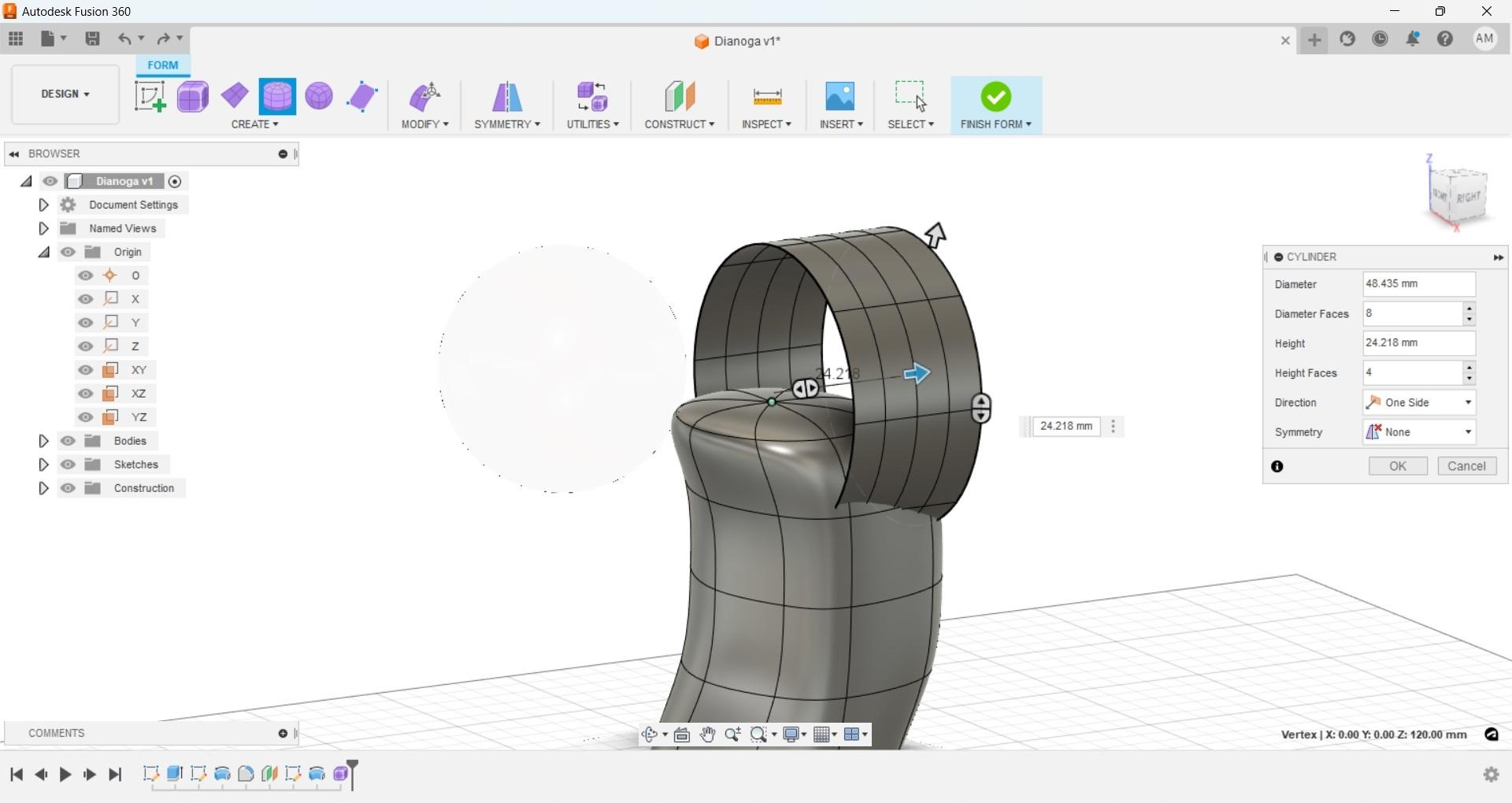
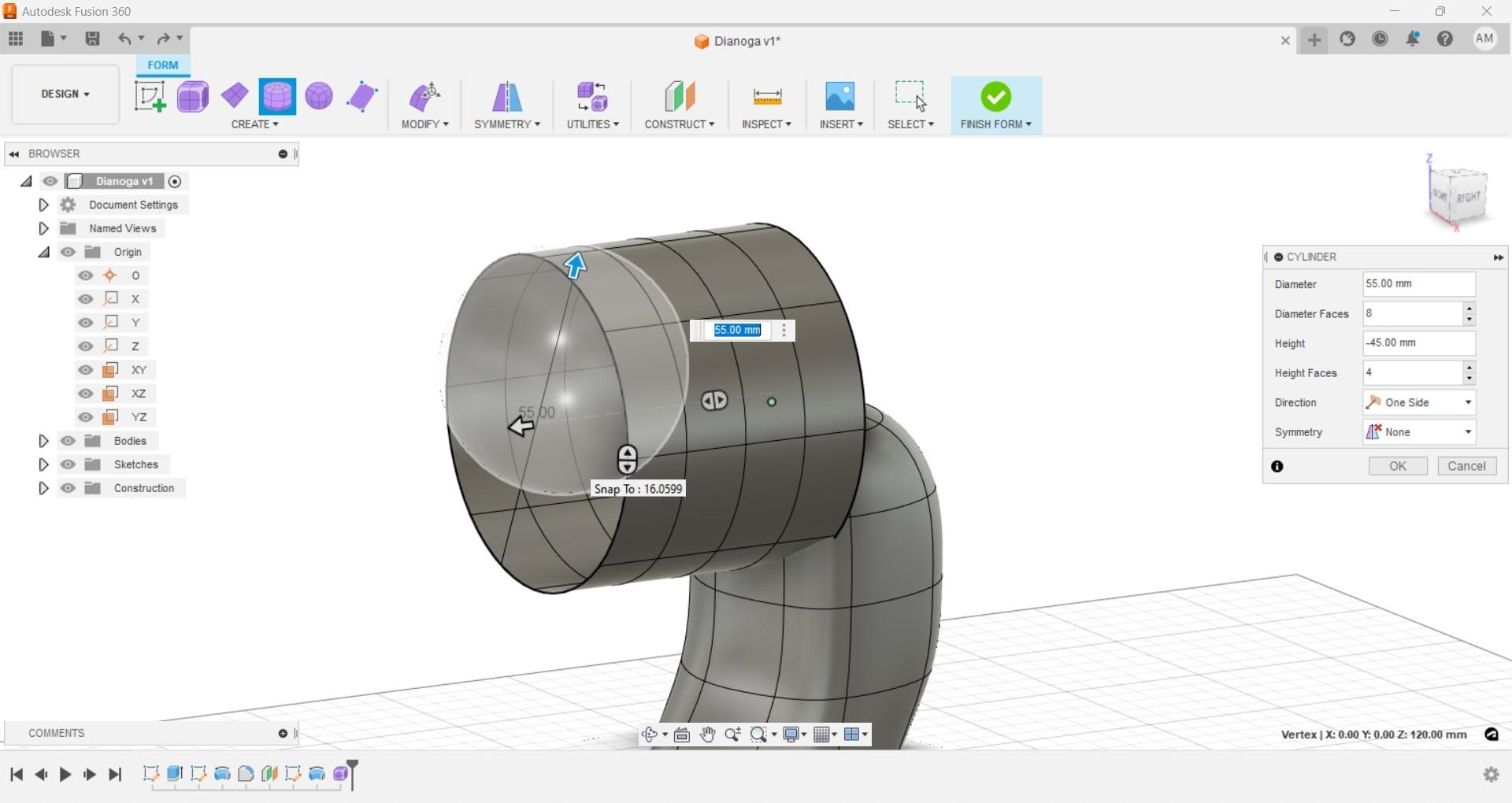
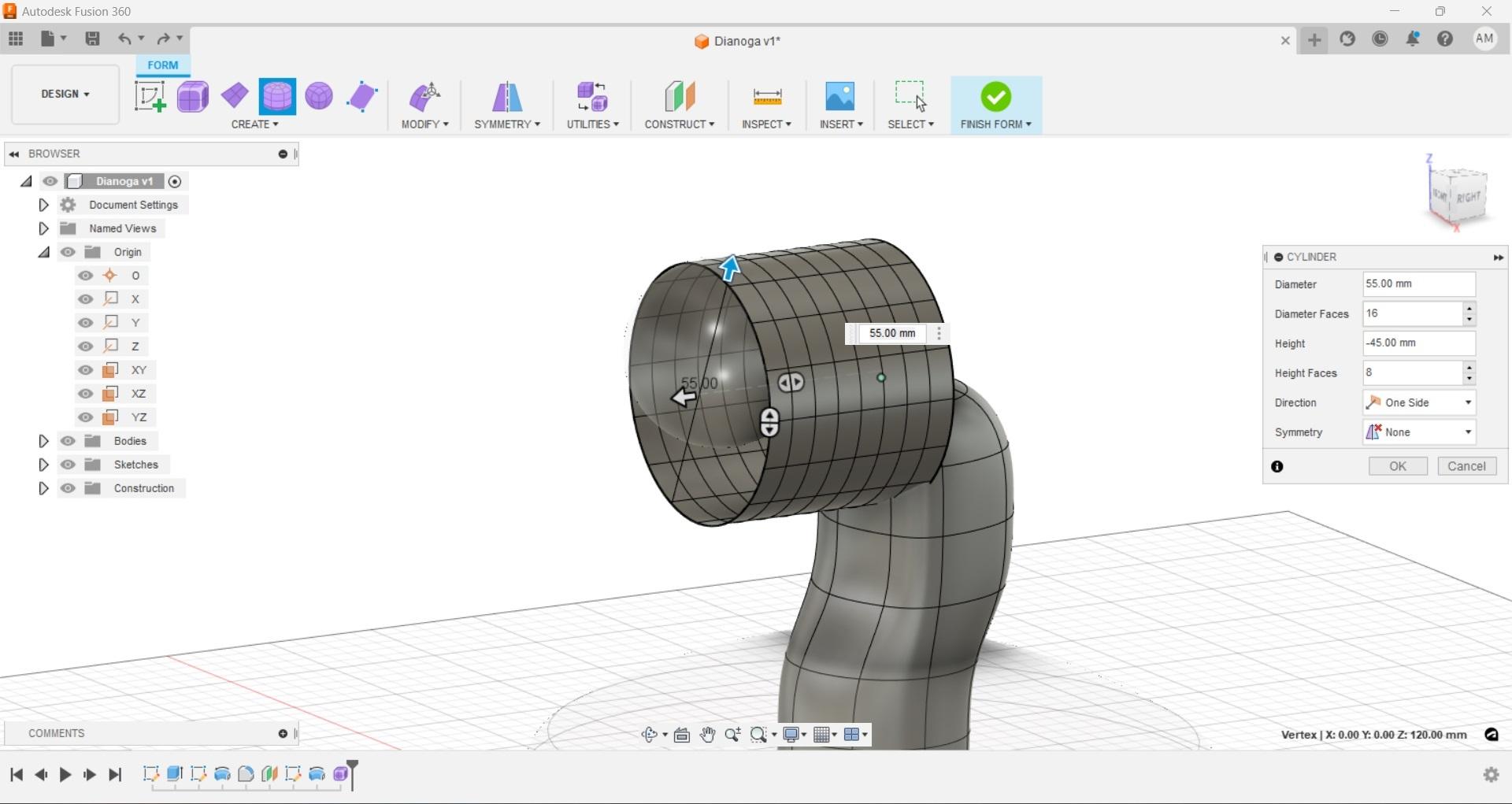
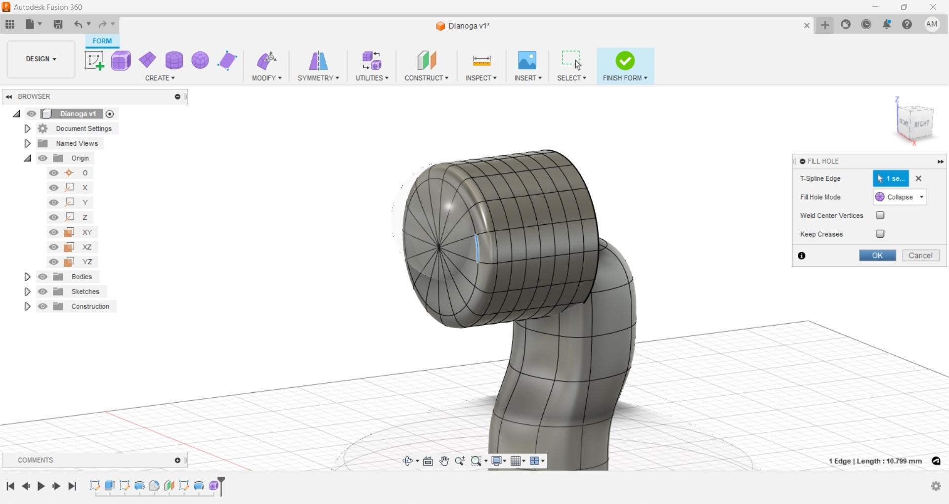
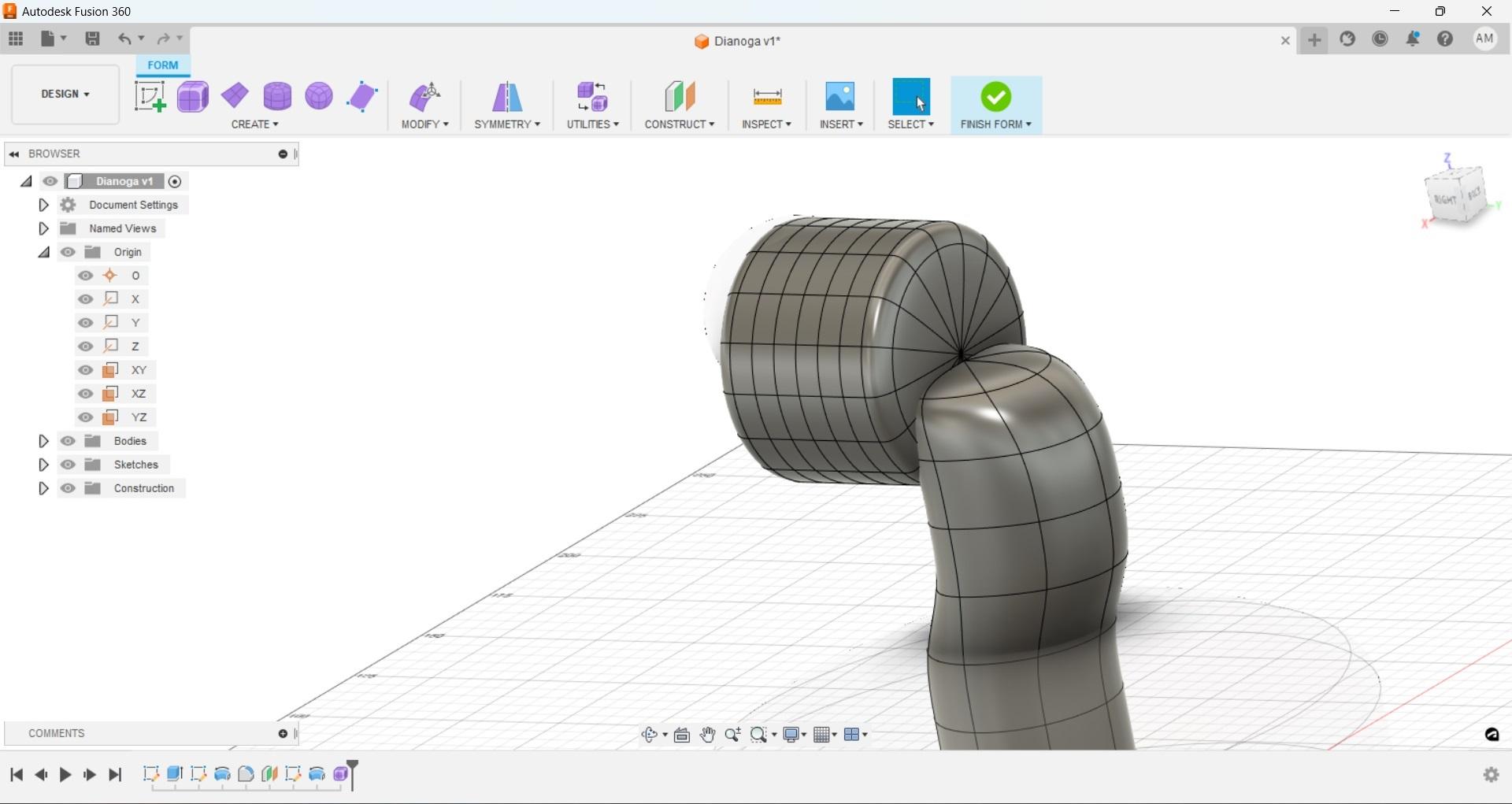
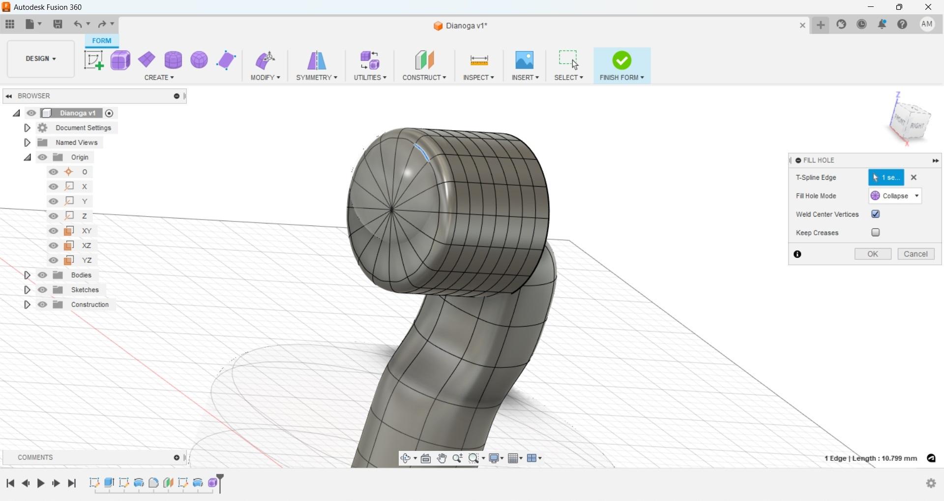
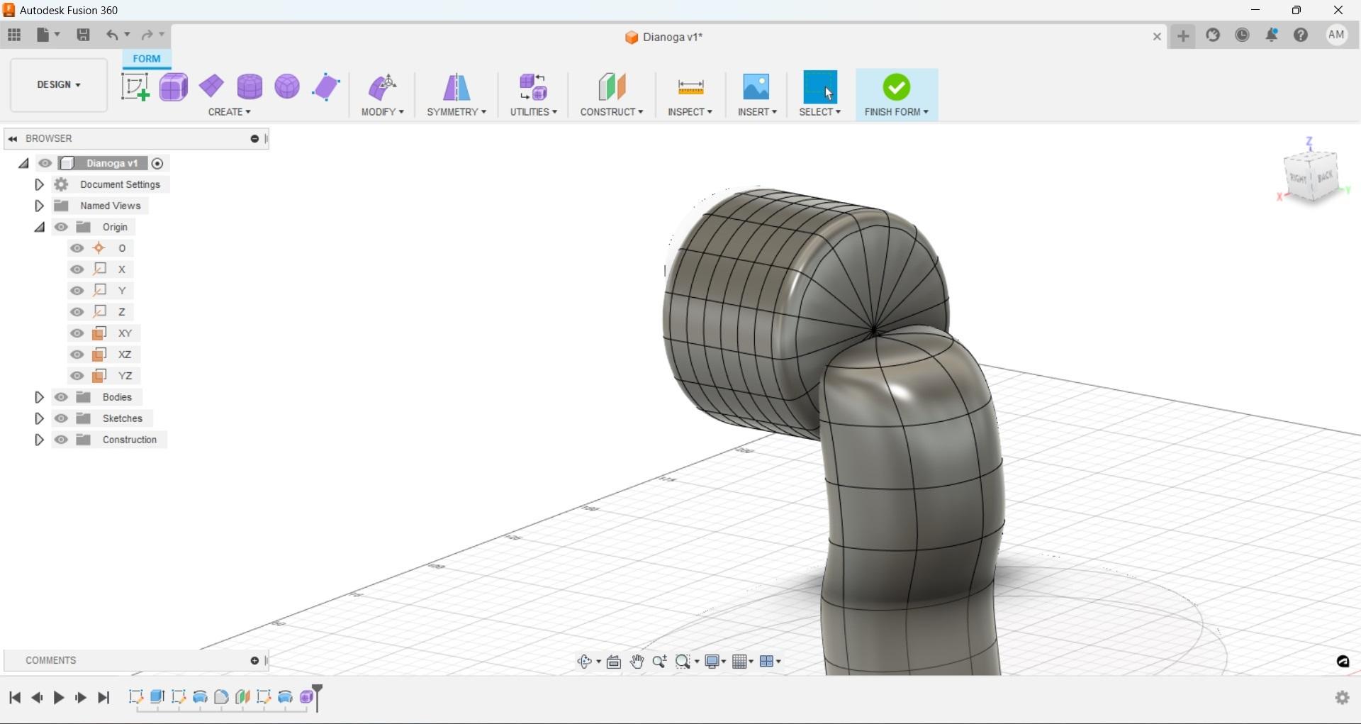
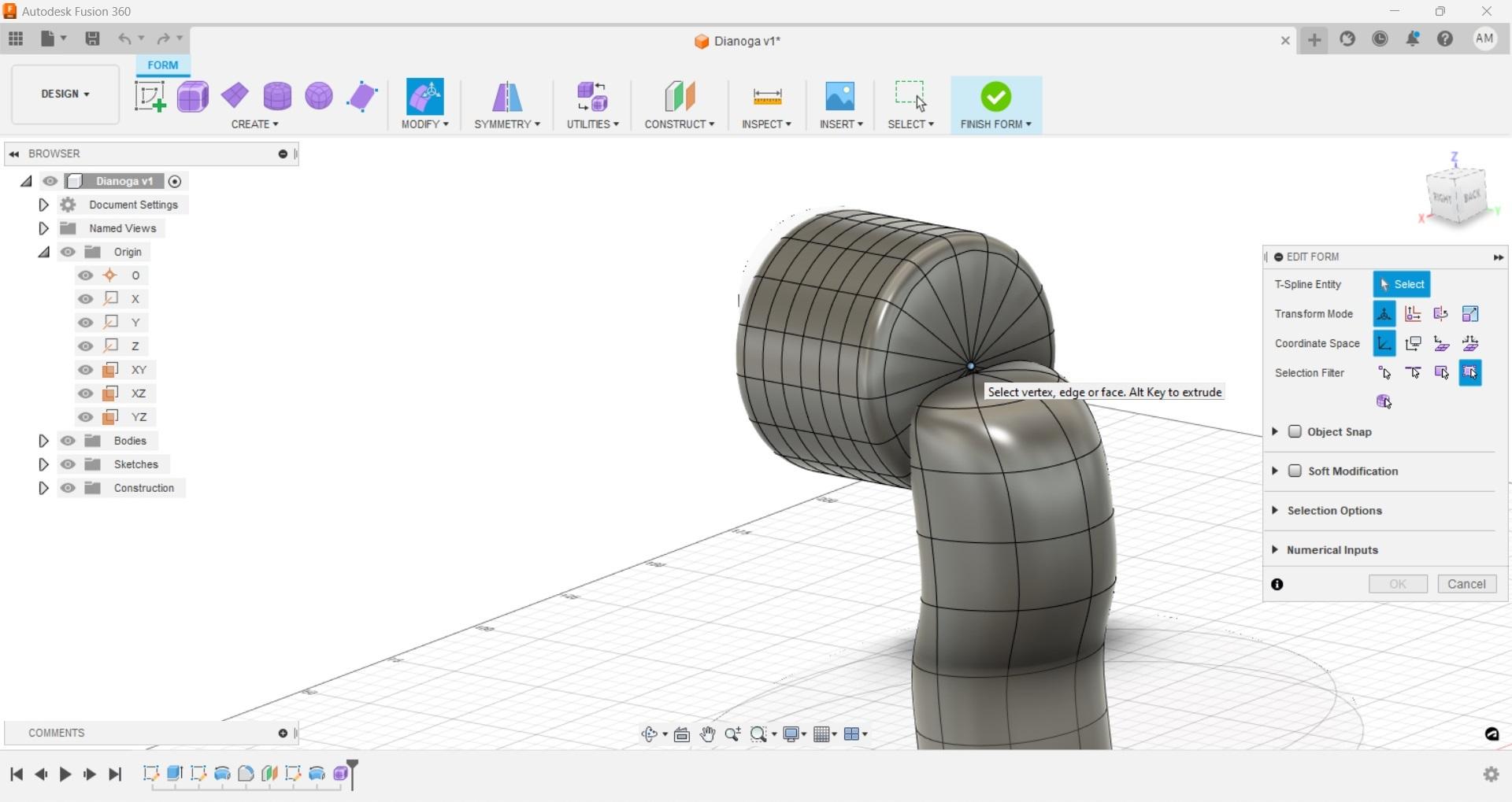
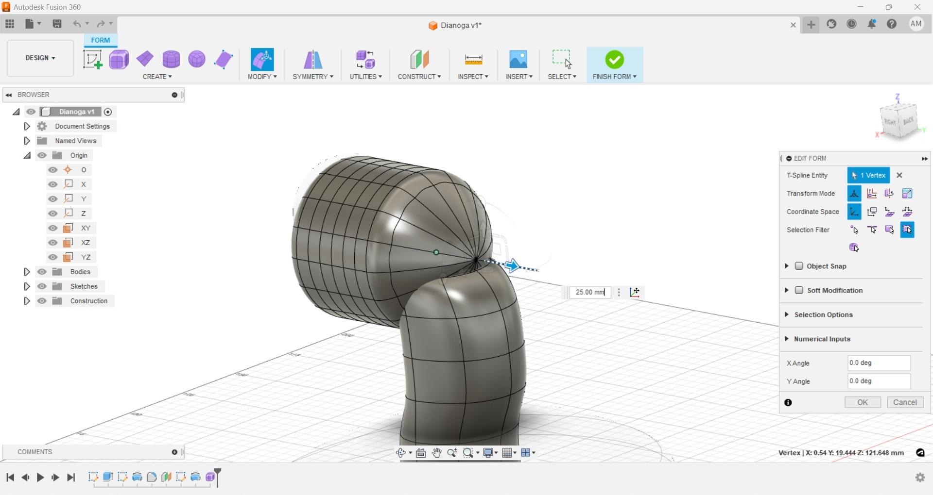
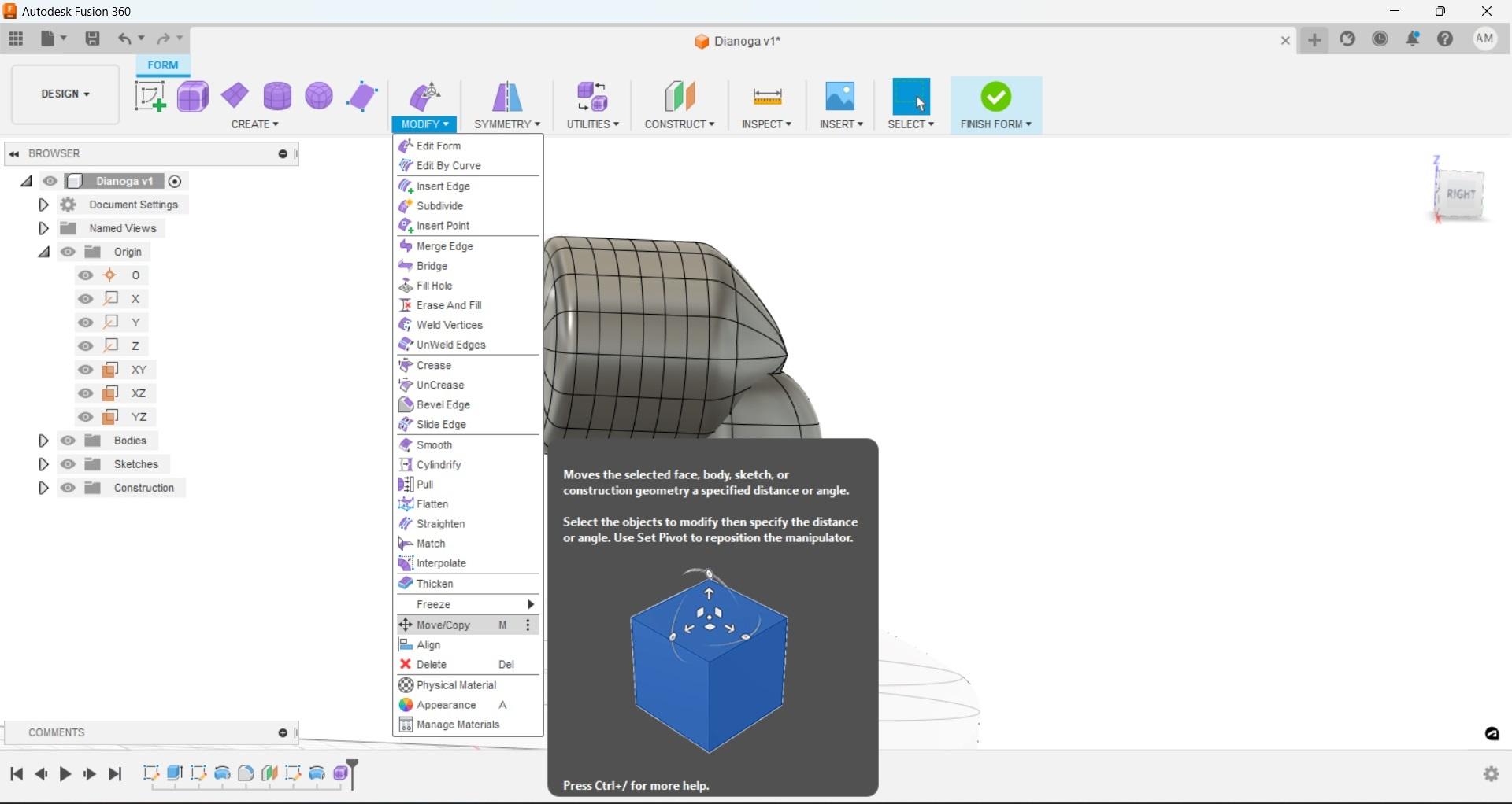
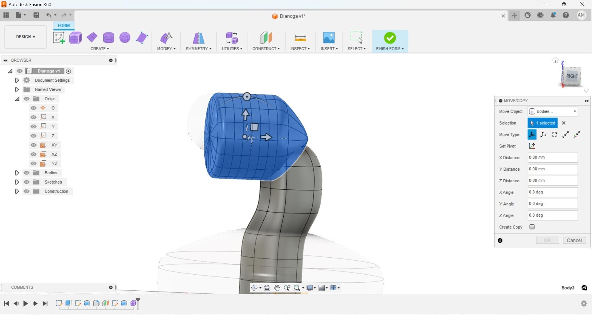
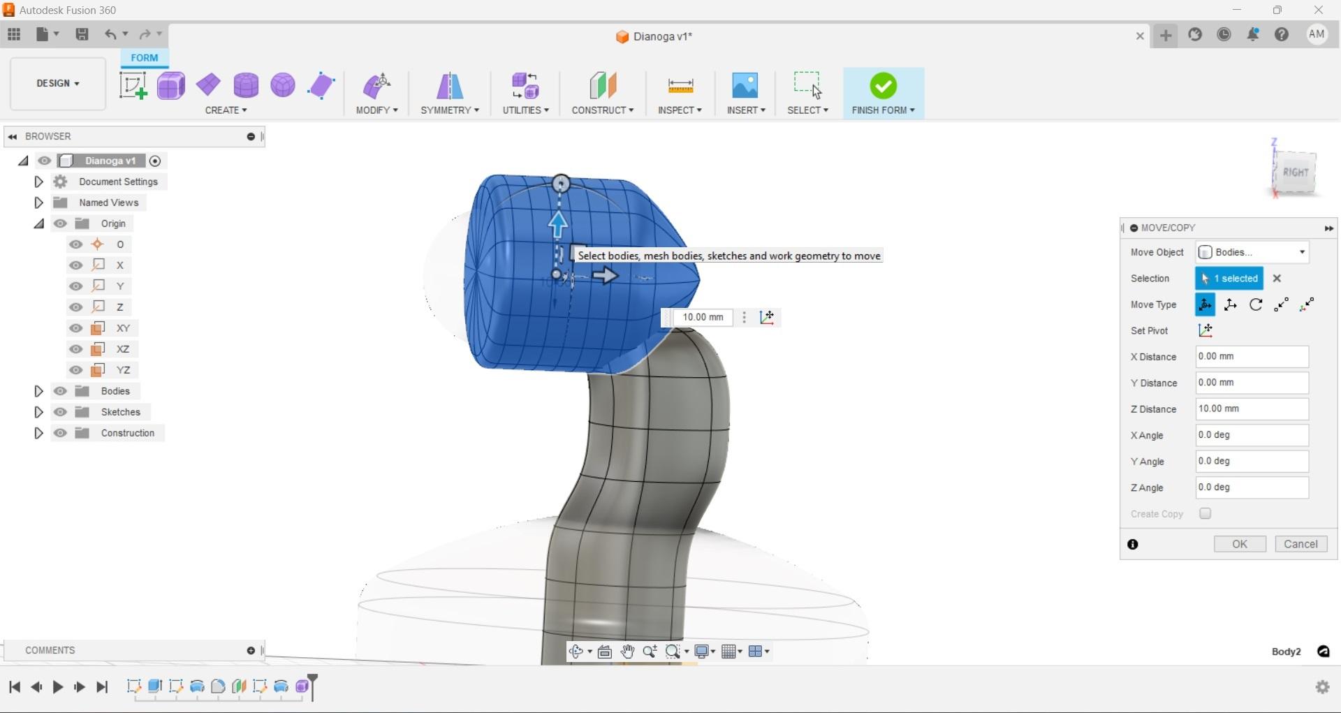
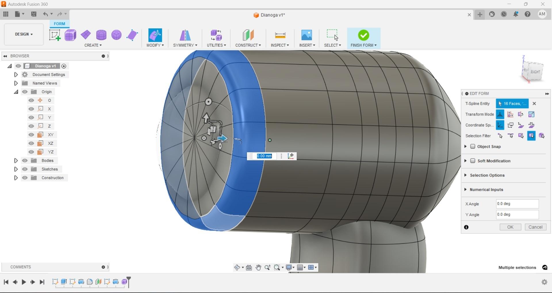
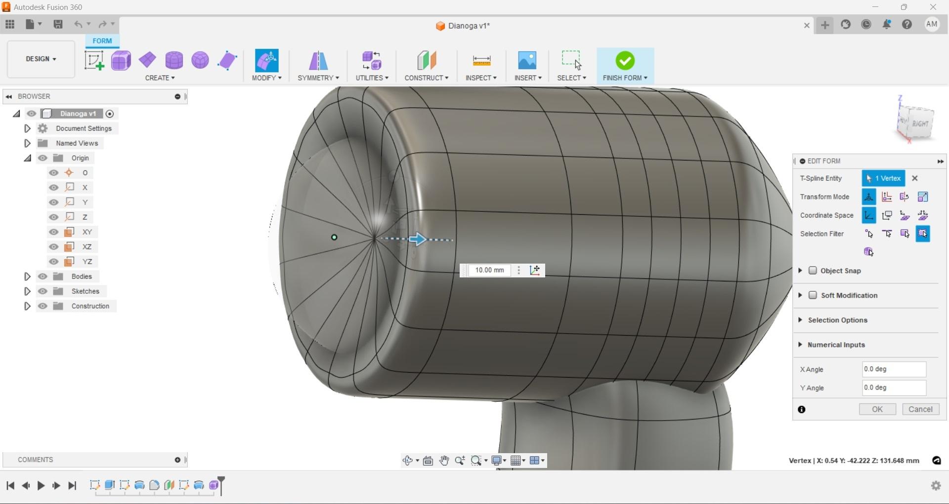
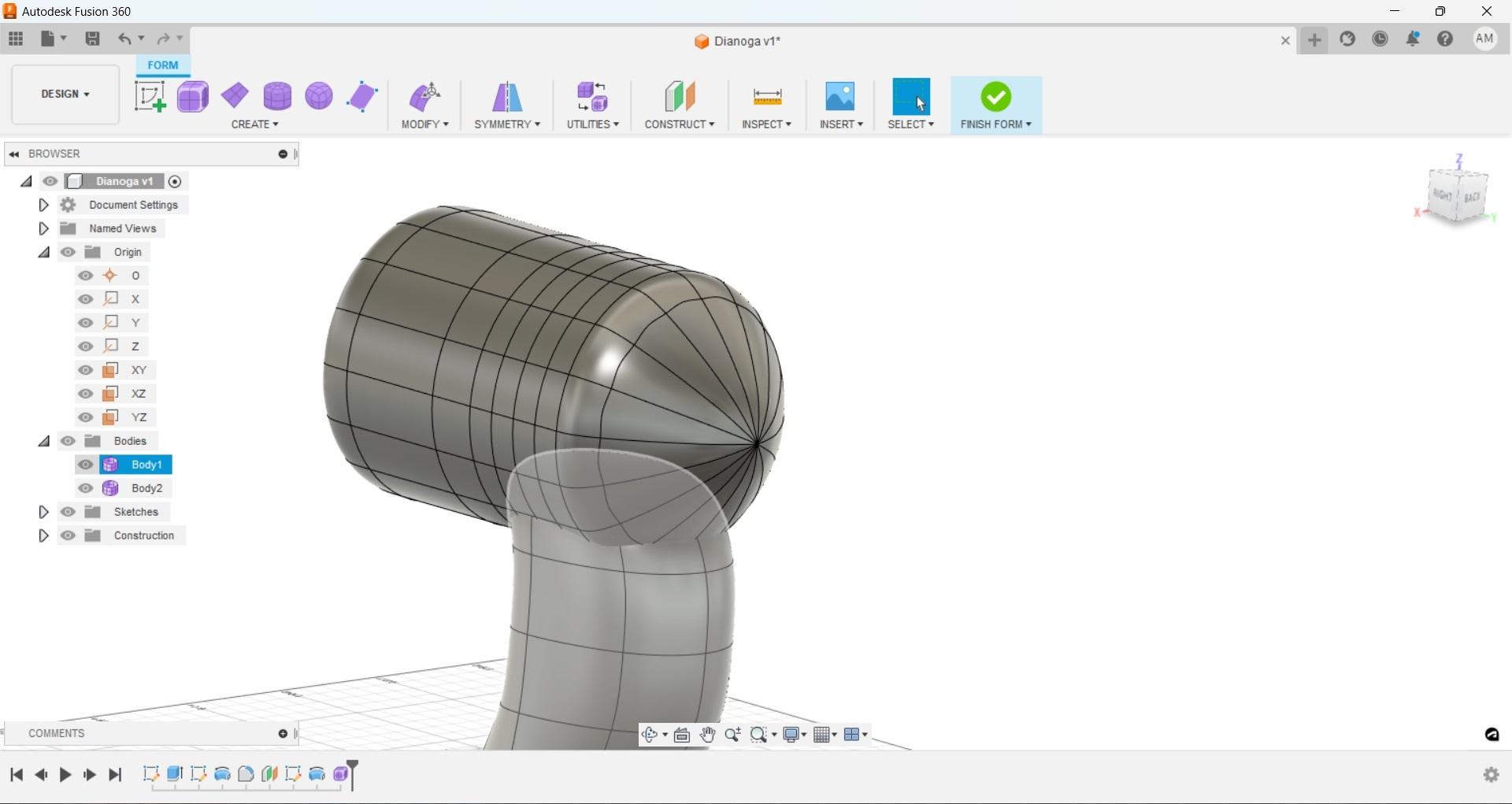
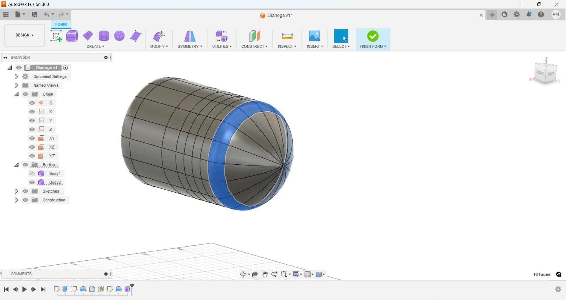
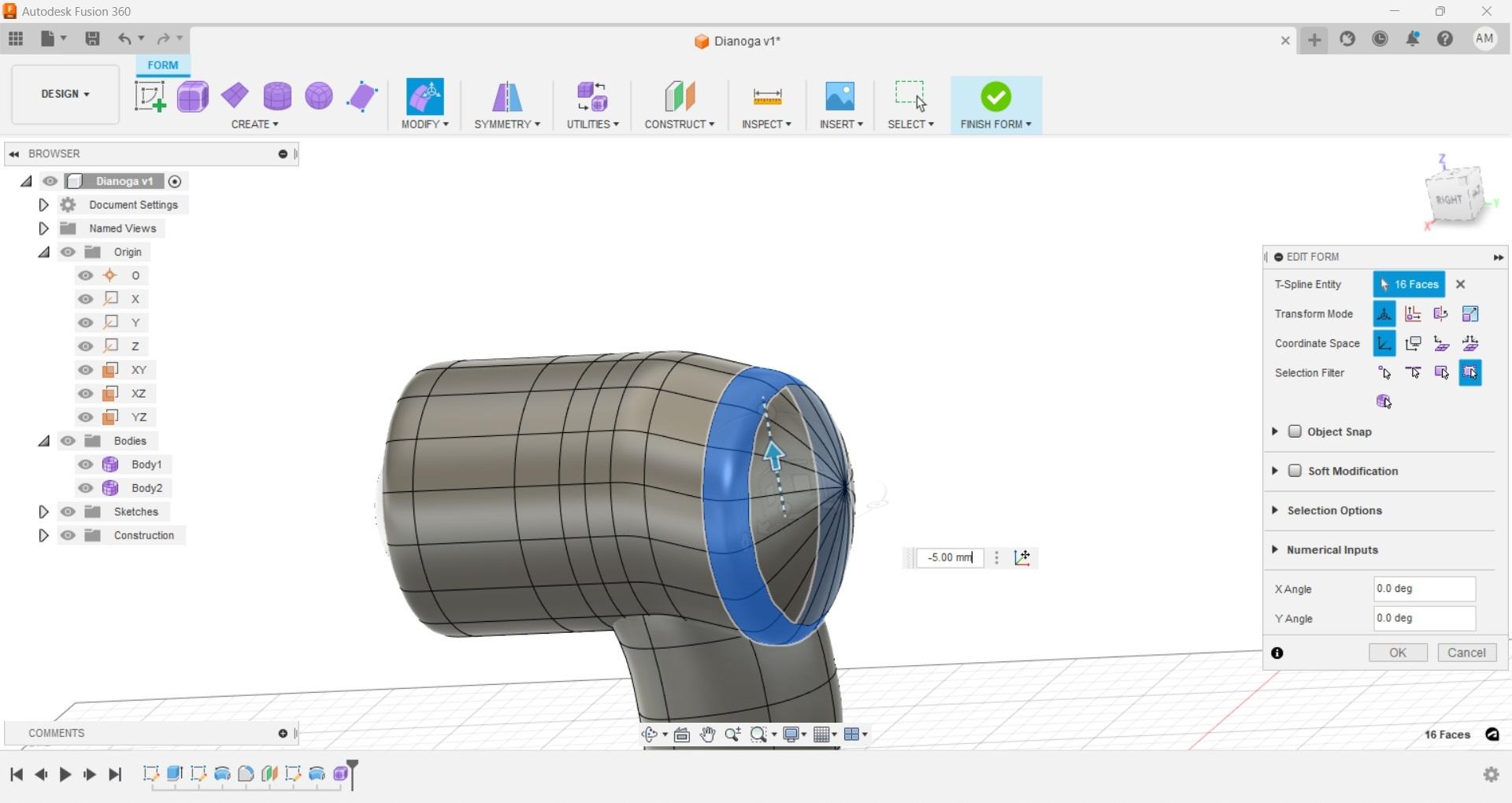
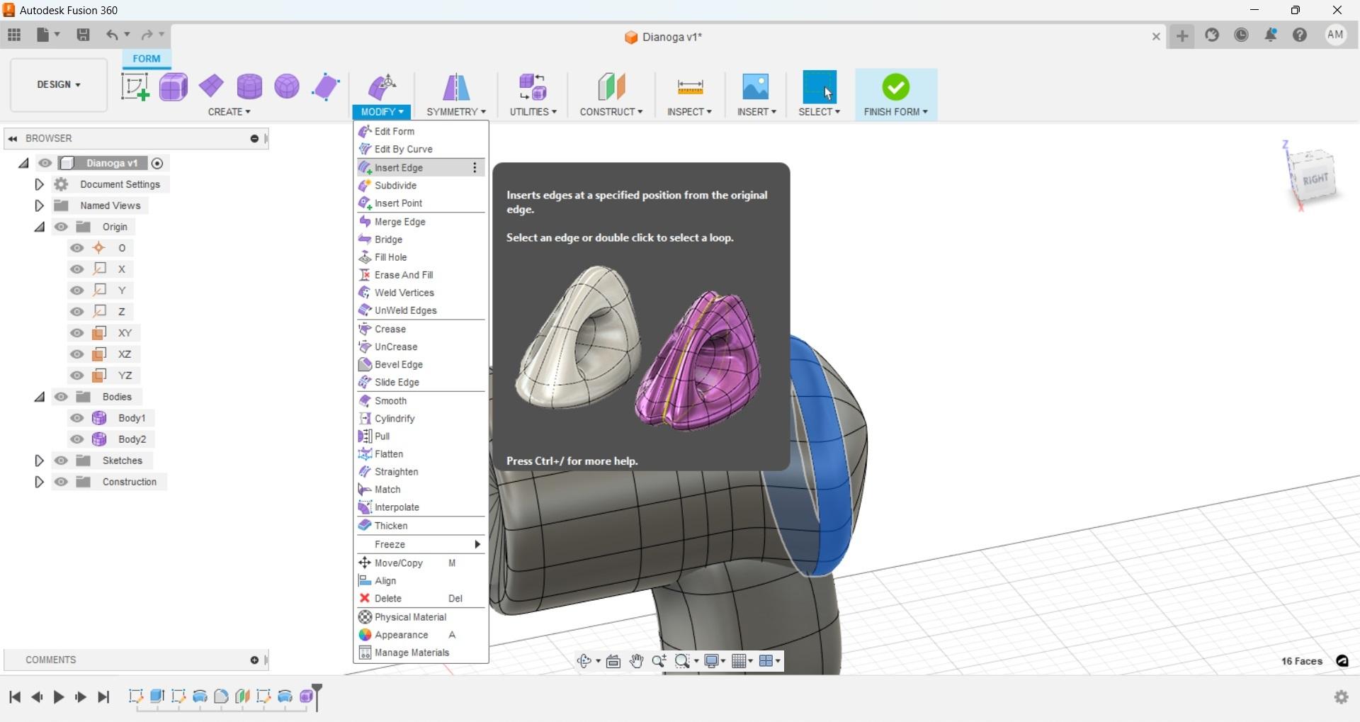
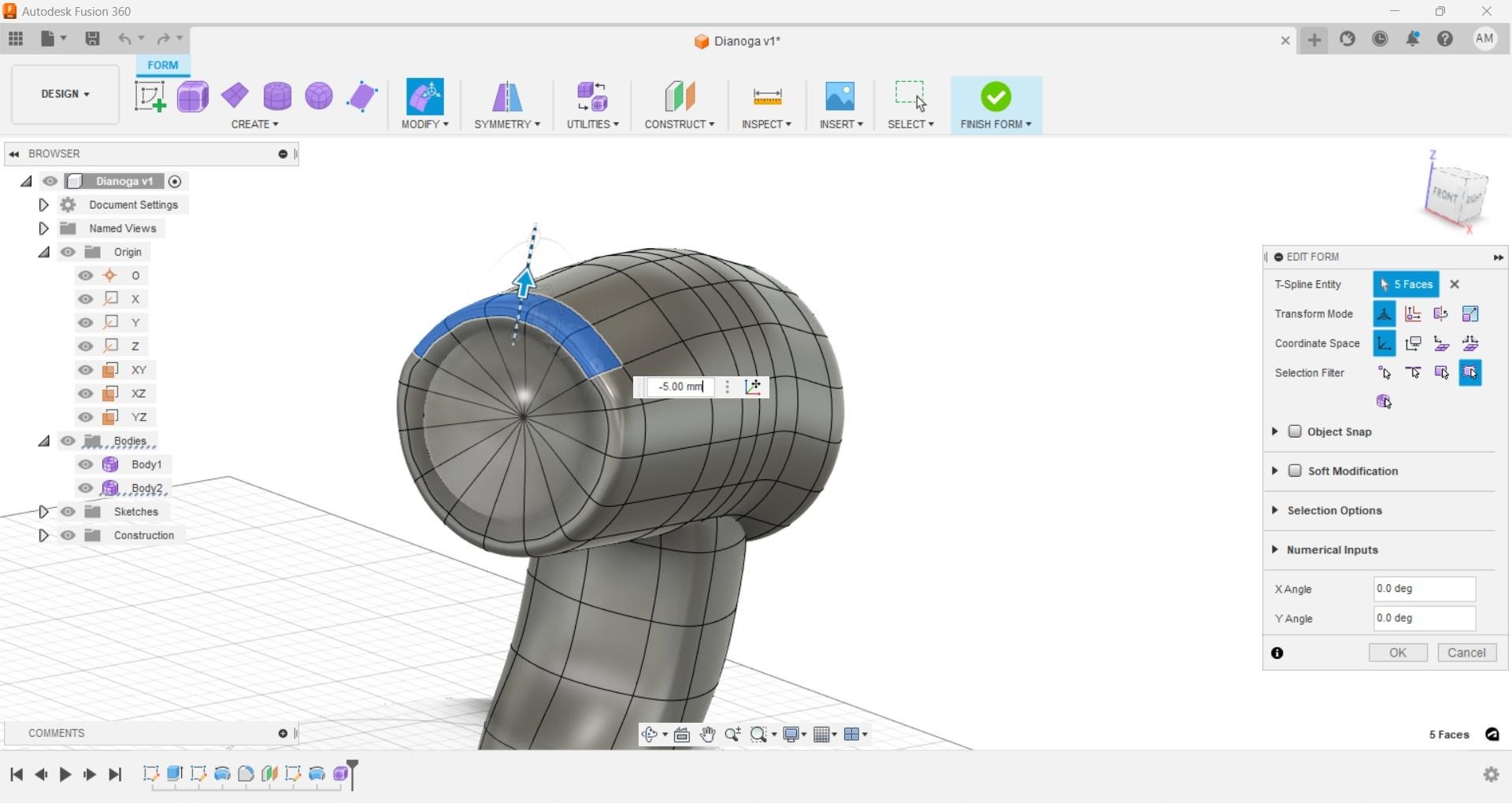
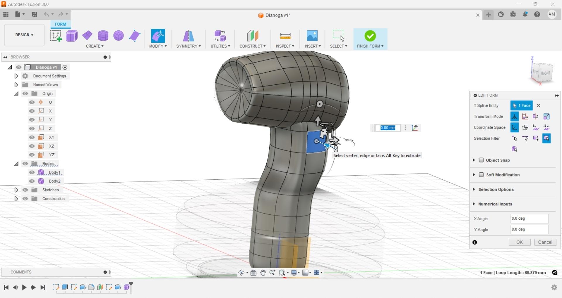
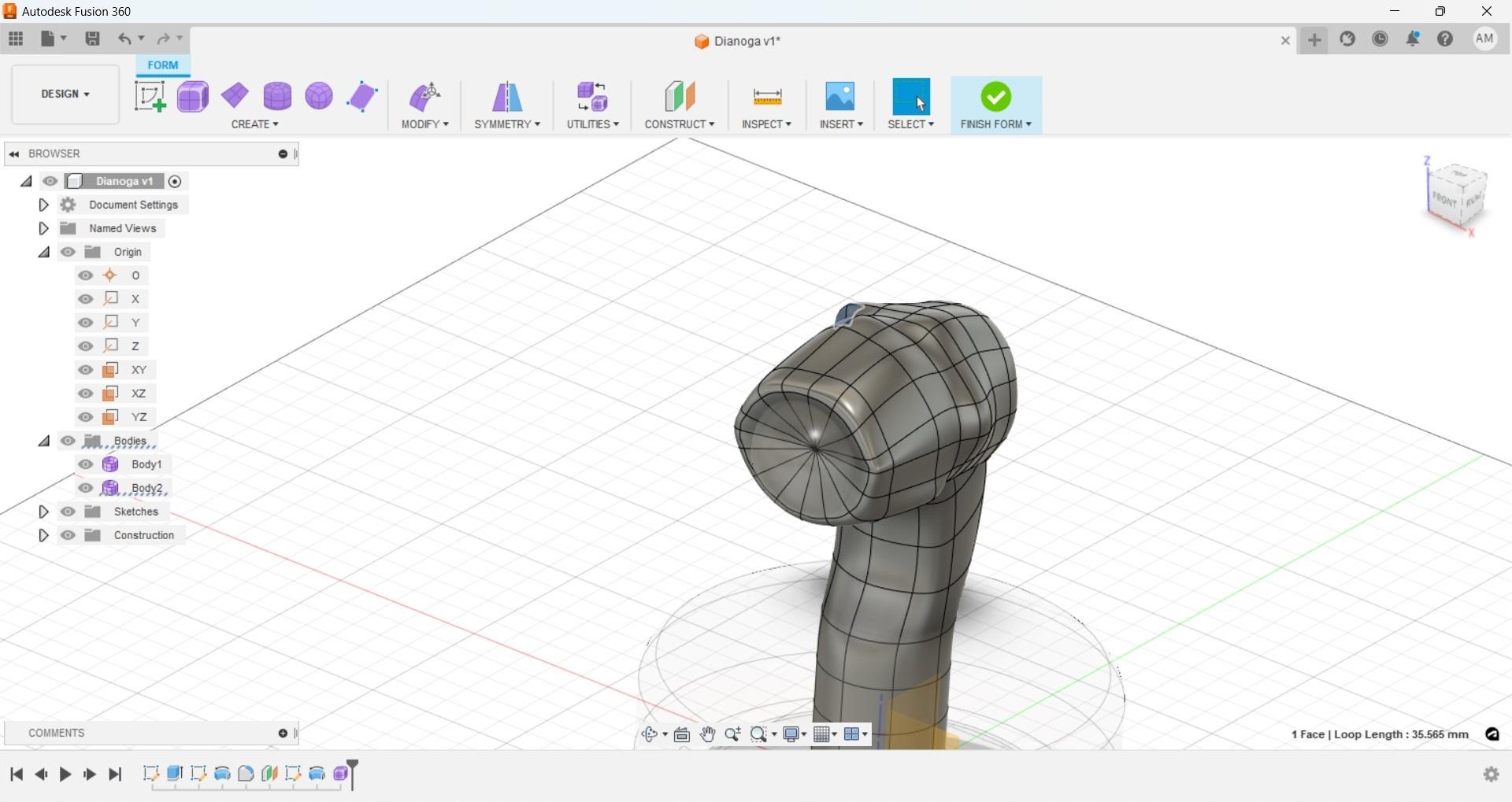
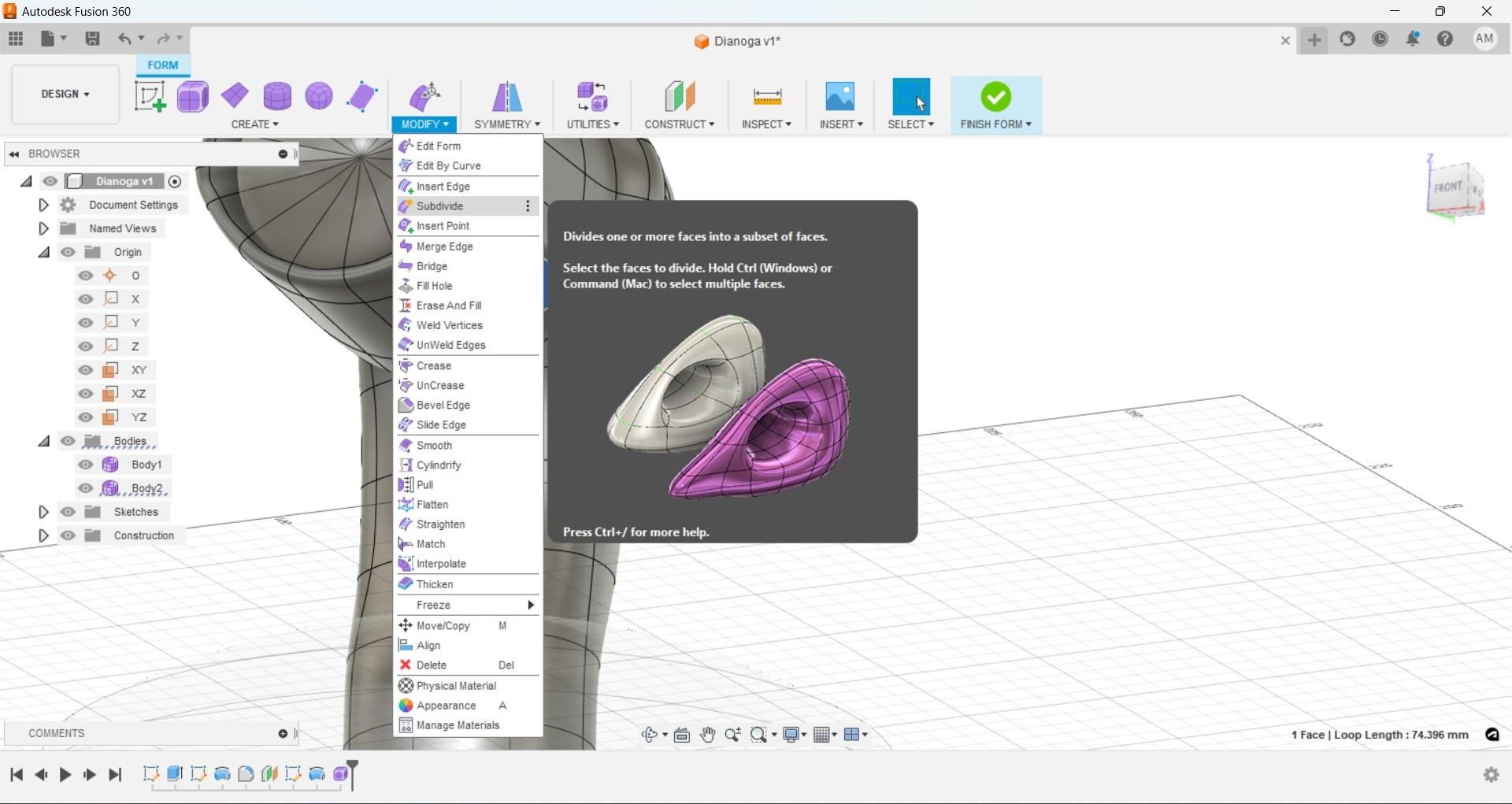
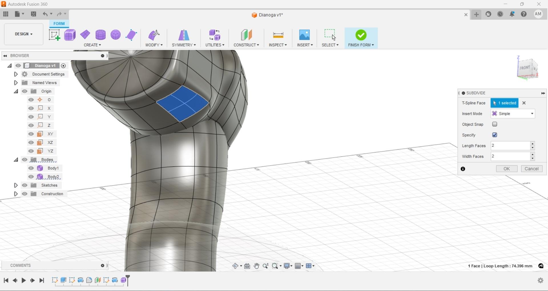
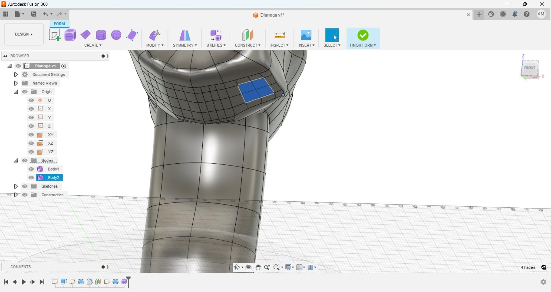
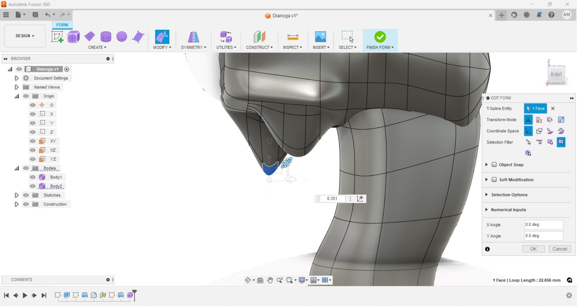
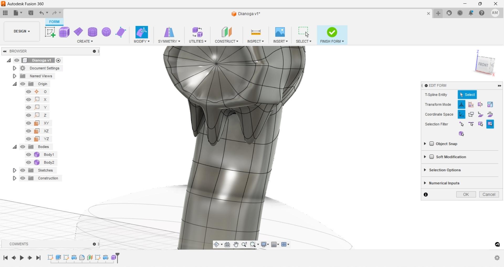
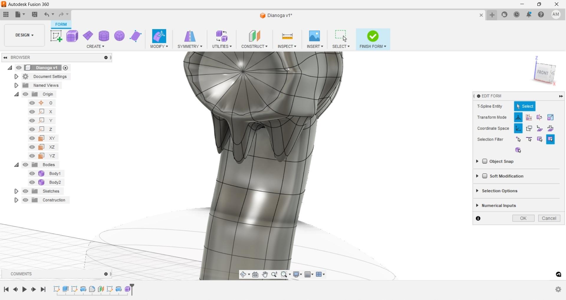
We are going to use much of the same steps for the beginning to create the start of the eye socket. While still in the freeform workspace create a new cylinder on the 'XZ' work plane, use the center point of the top of the neck for the center of the cylinder. Add additional faces, then select ok, then we're going to fill the holes again, however this time we are going to make sure that 'weld vertices' is selected. We did not do this on the neck cylinder which means if we try and select the center point of the neck and manipulated it there will actually be one vertices per segment going toward the center. With them welded there is only a single vertex that all of the segments link to.
By selecting single, or multiple vertices, faces, or segments we can use the modify tools to move, bend, and achieve different results to get an organic free form.
-In the free form workspace we also have the option to hide separate forms that were created, for instance we can hide the entire neck section so we can select all parts of the eye socket and move the entire body up to fit it to the eye.
-The center vertex in the eye socket can be selected by itself and moved in with the modify tools to give the socket some depth.
-Single faces can be selected and then subdivided with the subdivide command to give more sections to manipulate and add detail.
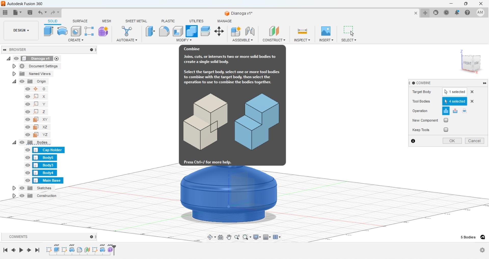
When you are happy with your results you can select the 'Finish Form' button just like you would complete a sketch. This will take us back to our main workspace, now that we are happy with all aspects of our creature and base we can select all bodies and use the combine tool to make them into a single solid object.
Exporting and Printing
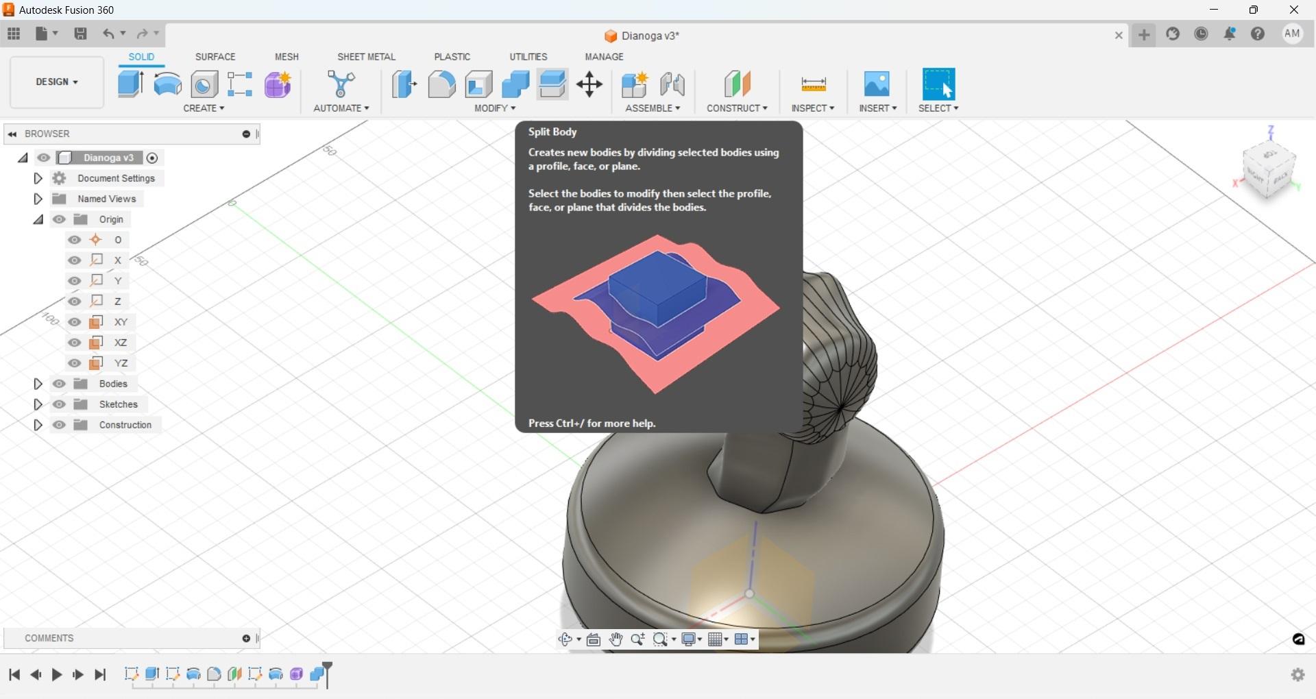
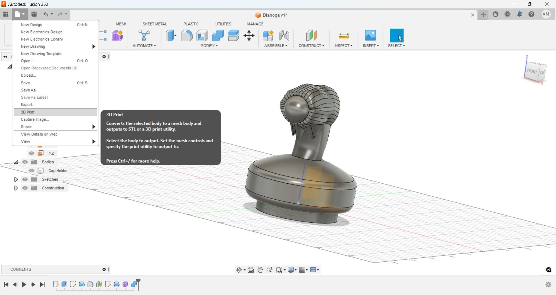
With our single body we can now use any method to export our model into an STL file to be printed. I used the '3d Print' option from the drop down and exported as an STL that way.
If your printer is large enough to handle the design then print it out with whatever settings and infill you feel is appropriate, keeping in mind that shell thickness and infill percentage will affect how buoyant the final product is.
If the design is too large to fit in your print volume, then use the 'split body' command and use the origin faces to cut your print into smaller sections. Keep in mind you will need to export those sections and you will have a seem running along your final product which will require greater attention to gluing and sealing to prevent water from leaking in. With 145mm diameter that puts this print a little less that 5 3/4" in diameter which should still fit on an average print bed.
Another note on filament is that ABS and PLA are probably not the best options for something intended to be left outside full time. PETG and ASA filaments should be able to handle the extended time outside in sunlight. My print was completed in resin, which should be ok in the heat and sun.
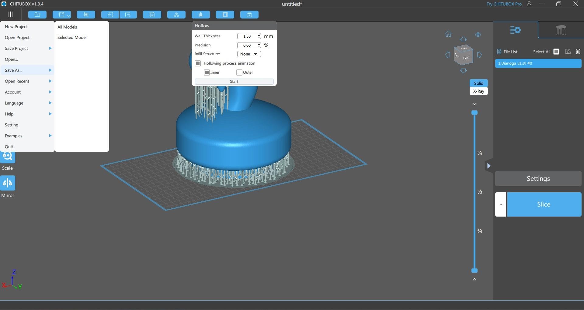
We didn't (and probably couldn't) have used the shell commands within Fusion to hollow the model, however this can easily be done in most printing programs. You can download Chitubox and hollow your models out to whatever dimension you wish and save that as a STL for free if you so desire.
8 Post Processing, Painting
I didn't take any pictures for the post processing and painting. I didn't have a helper and in the interest of safety and not making a mess it was easier to proceed without. If you have any questions or need additional images for this part please message me and I will respond with whatever details you need.
I no longer have a FDM printer and this is one of the places where I would have rather used one, with resin it's recommended to add holes for the trapped resin to drip out, for me this will require filling those holes. If you used a FDM printer then lucky you, just rip those few supports off. Since XTC-3d will be used to seal the print it makes the work of cleanup even easier, as it was intended for this very purpose.
Apply XTC-3d per instructions on packaging, with a minimum of two coats. After the second coat wait until it has cured then lightly sand and wash everything, and begin painting. Less is more when using epoxy as once the heat kicks in it will harden quickly. For this project I was ok with drips and slop because that matches what I was going for.
Masking and painting are fairly straight forward, you can add as much or little detail here as you'd like so long as you do it in a well-ventilated area with all appropriate protective gear.
After painting I added an additional 2 coats of XTC not only to help with additional sealing, but to give our project a slimy wet look. In addition, I cut a few strands from a broom and attached them with wet XTC to add a little detail. You can use a lighter to briefly heat the strands and give them a more scraggly look.
With everything dried and cured spray a few nice even coats of clear UV protective lacquer, mix some 5- or 30-minute epoxy (30 if you can as it will hold up better in the long run) and use it to attach the base from your old float to the new one. Once that has set, add a fresh chlorine tablet and enjoy your new pet keeping rebel scum and algae out of your pool.
Bonus 1
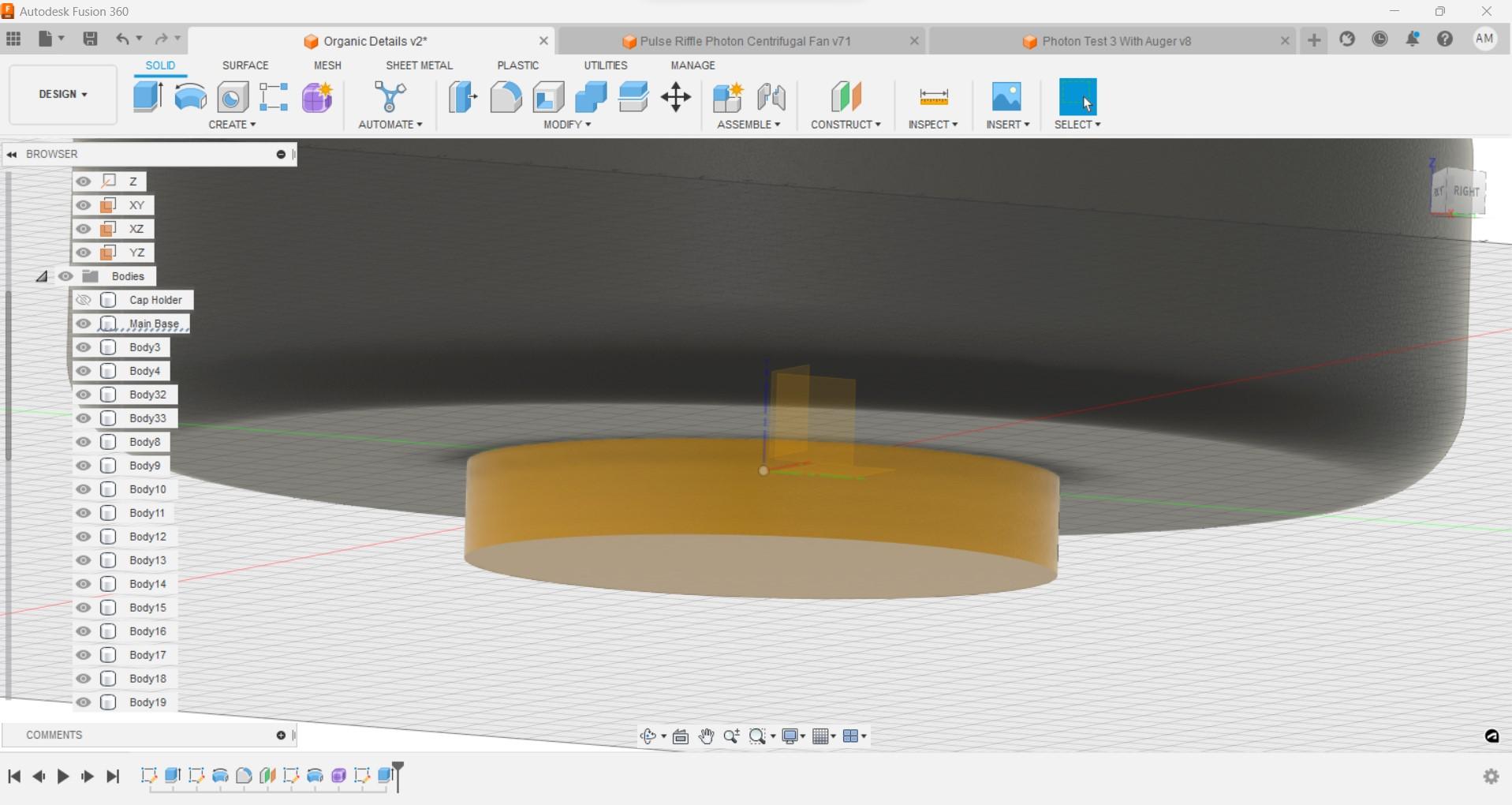
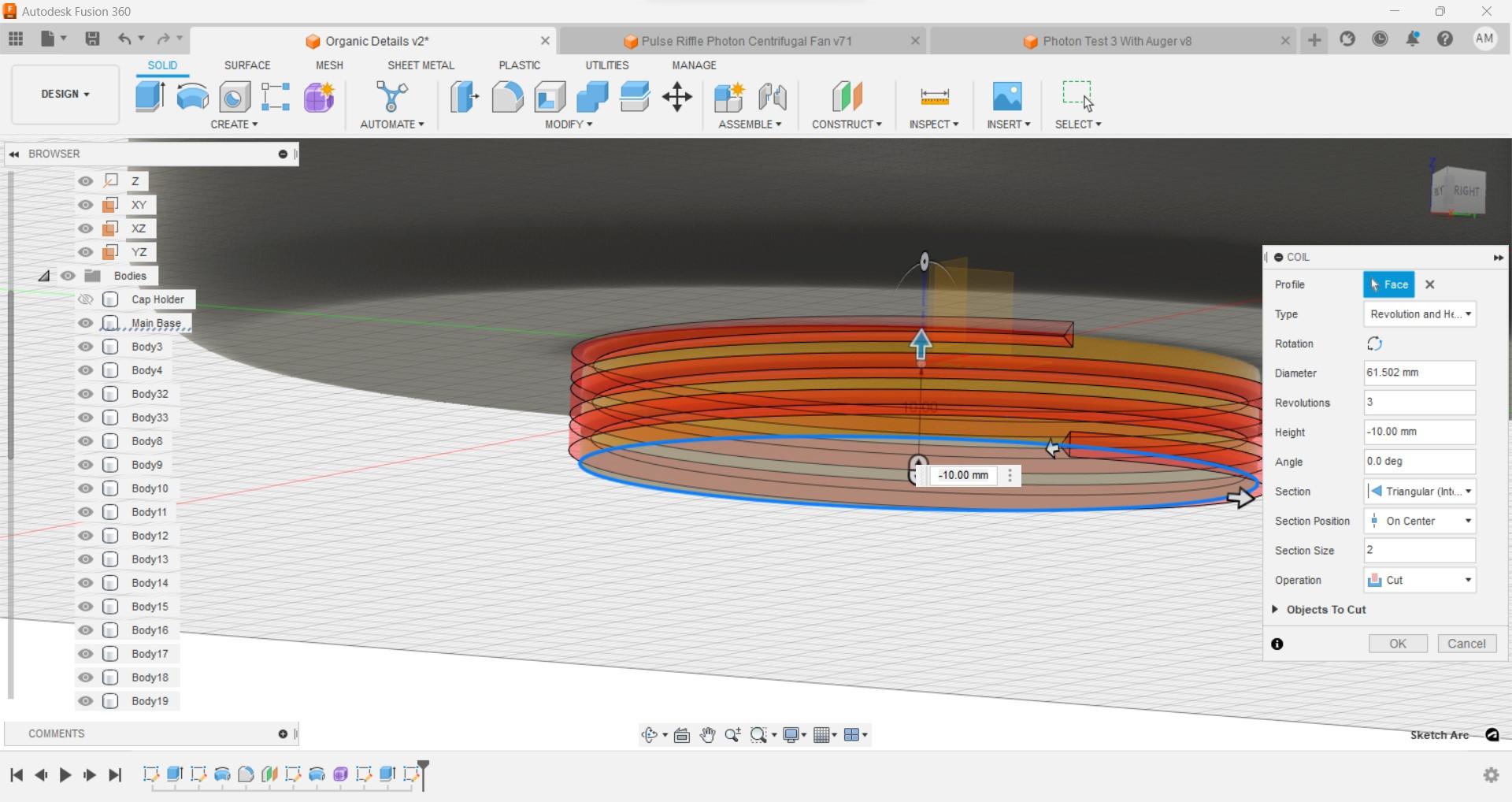
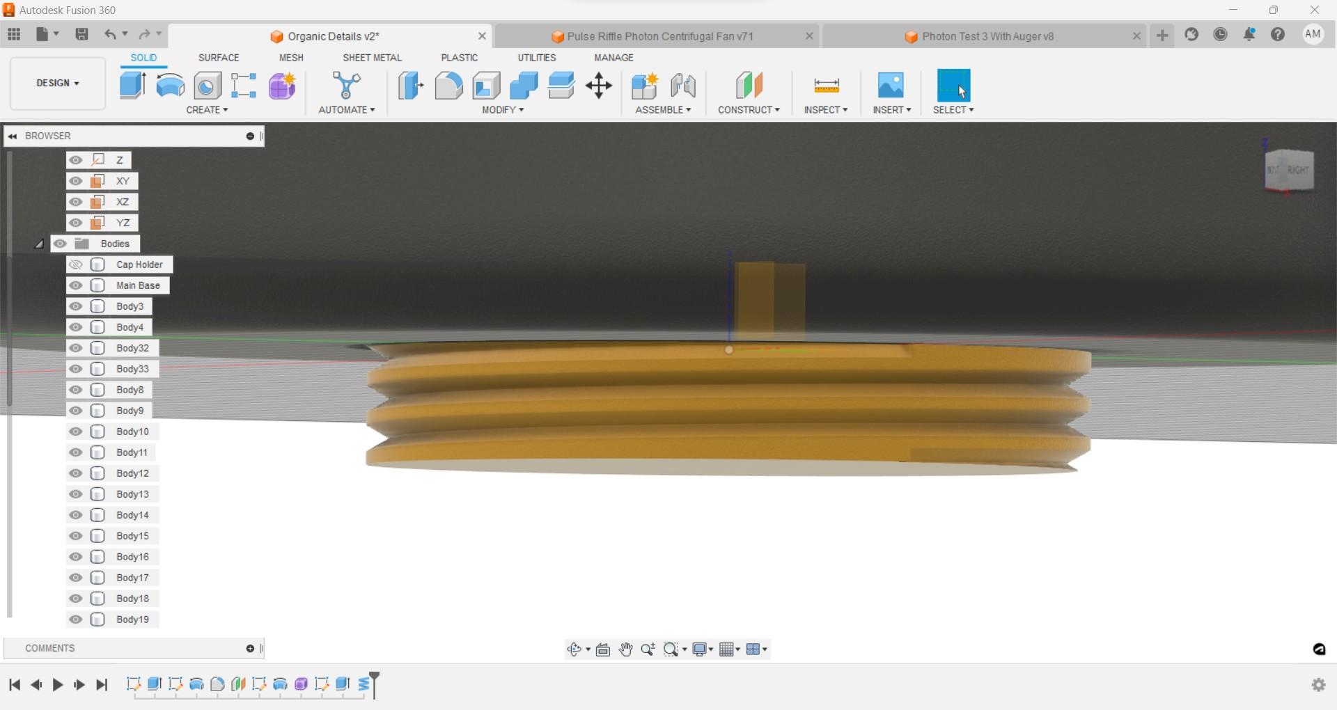
For those of you that might be attempting this with a different type of holder, perhaps one where the base is not a separate part, I've included a few pictures of how you can use the coil feature to cut the threads into a cylinder so that you can make a float that works for you.
The process is relatively simple and because we saved combining parts until the end you can measure the dimensions of your old threaded part, using the diameter for your cylinder, the number of screws for the number of revolutions and the height you can easily make a custom thread for your particular part. I would recommend only printing this piece out first to ensure that it fits before combining it with the rest of your creation. Once you have a piece that has the correct threads you can be sure that it will work when you print your final piece.
Bonus Bonus
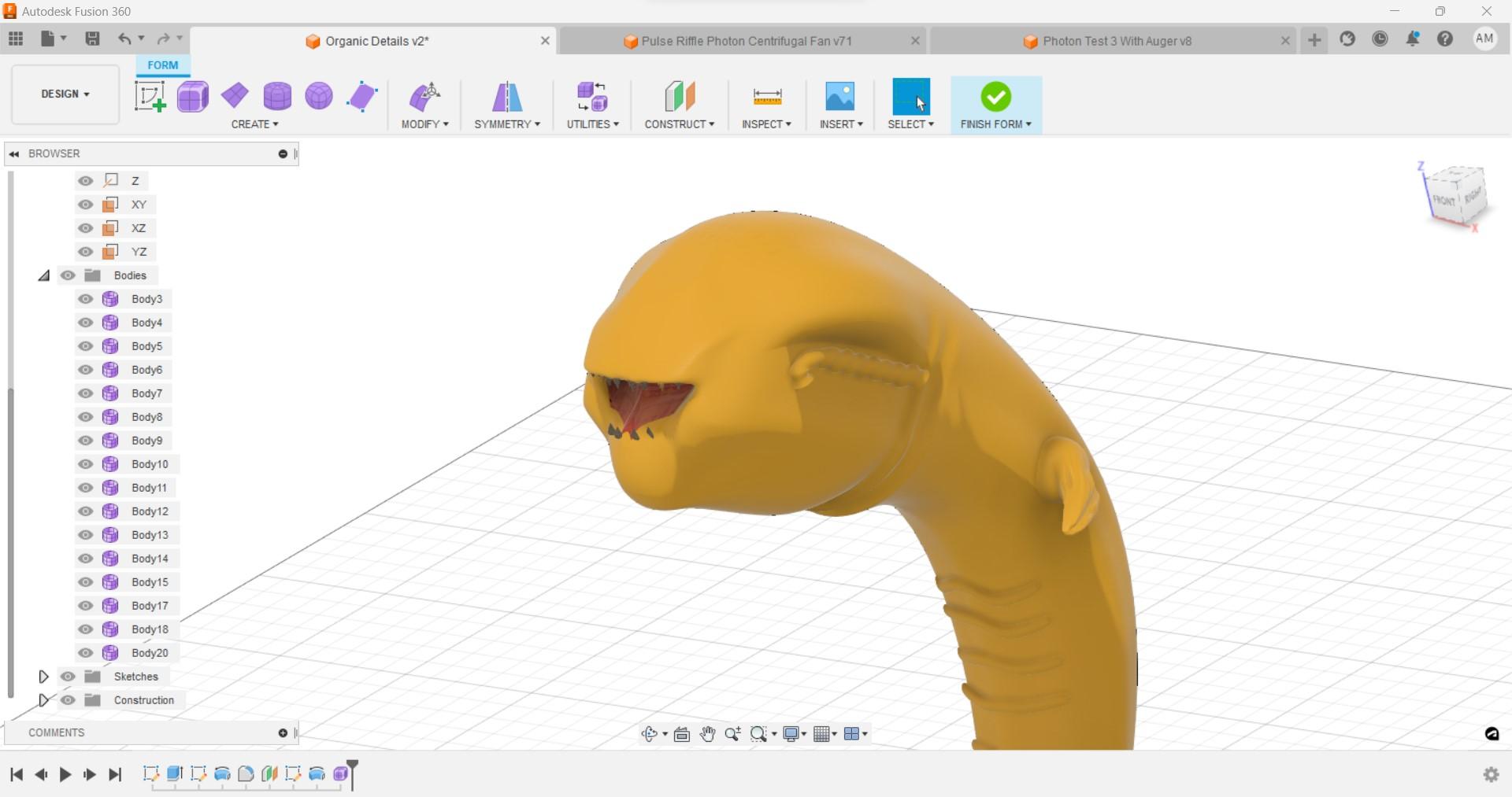
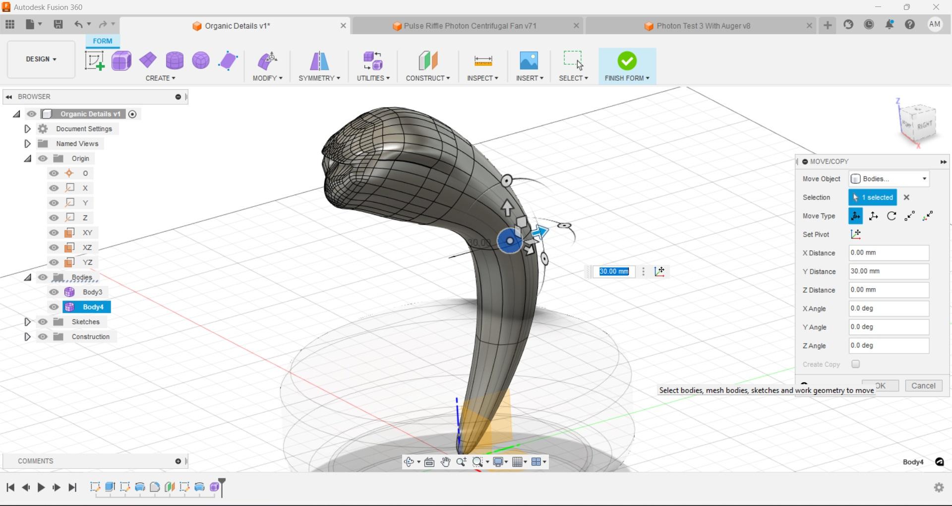
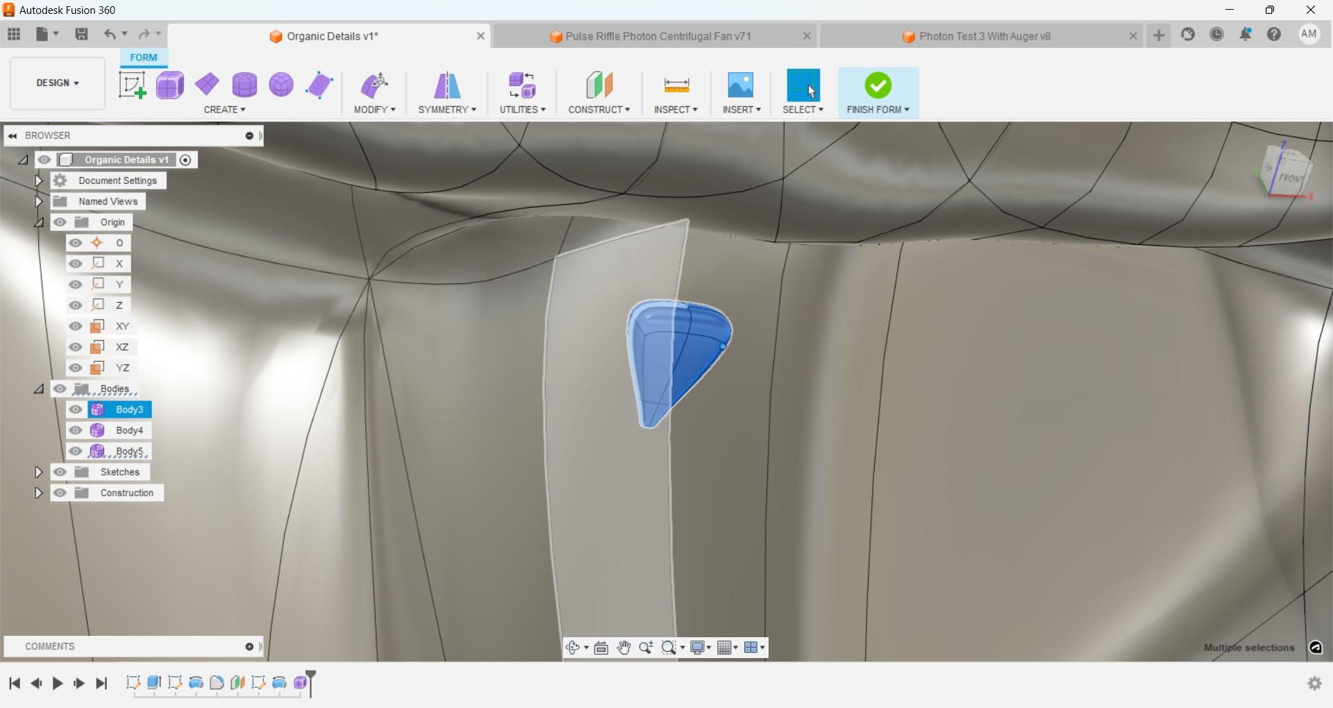
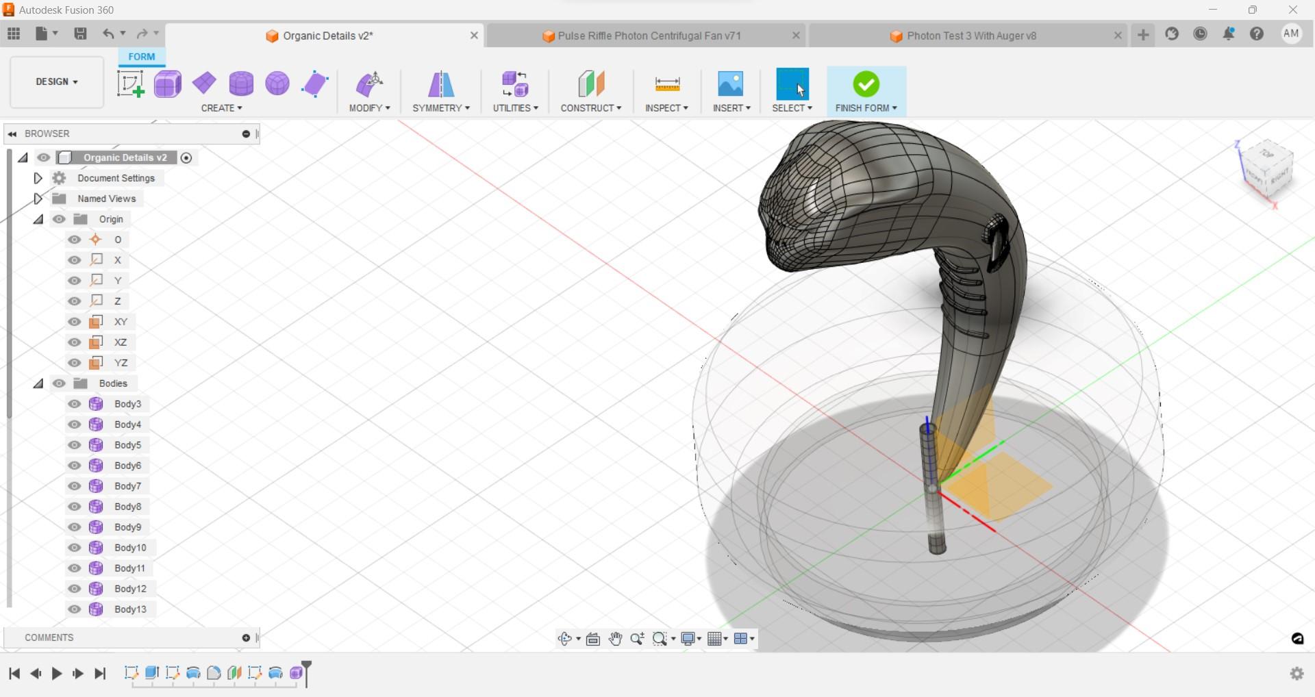
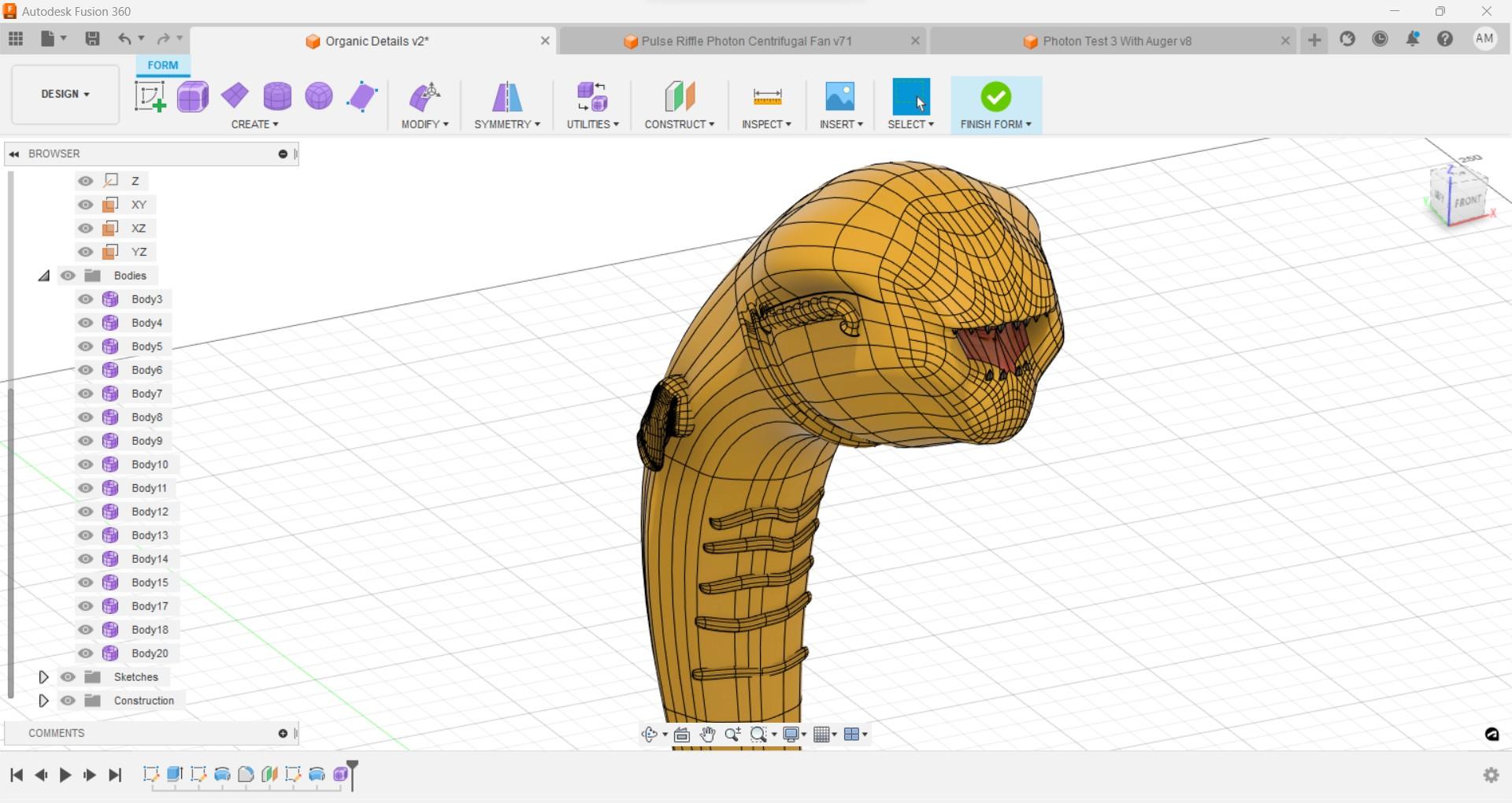
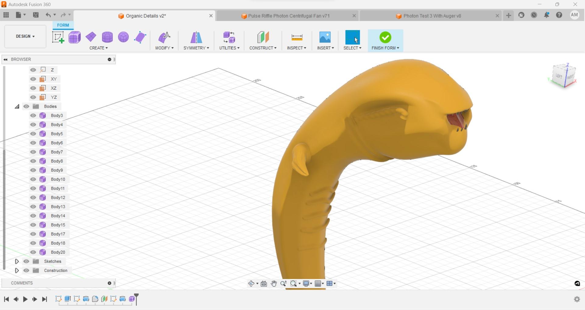
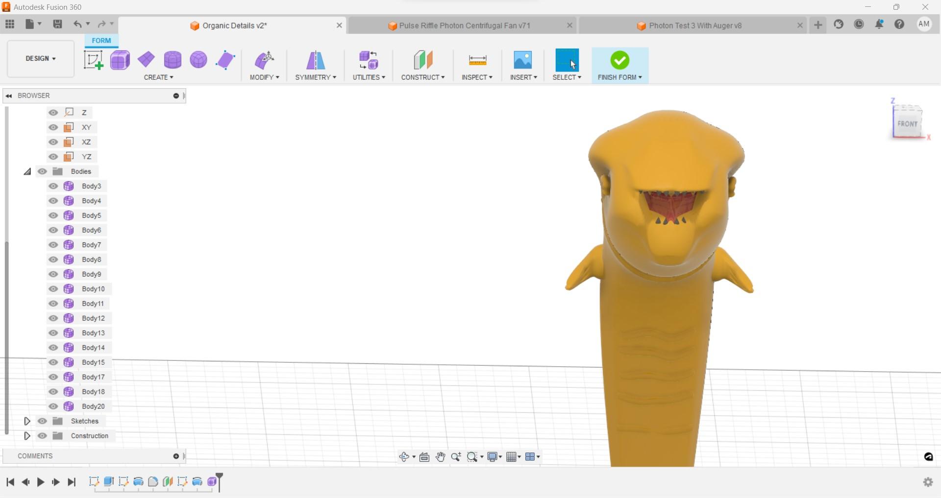
For this instructable I went with a very basic design with only a little detail and basic manipulation that would be easy to follow along with. I have included an additional sculpt of an alien chestburster. I made this using the same basic techniques taking a little more time with details. As you can see Fusion 360 can be used to create some pretty decent organic bodies which is an amazing feature for a CAD program.