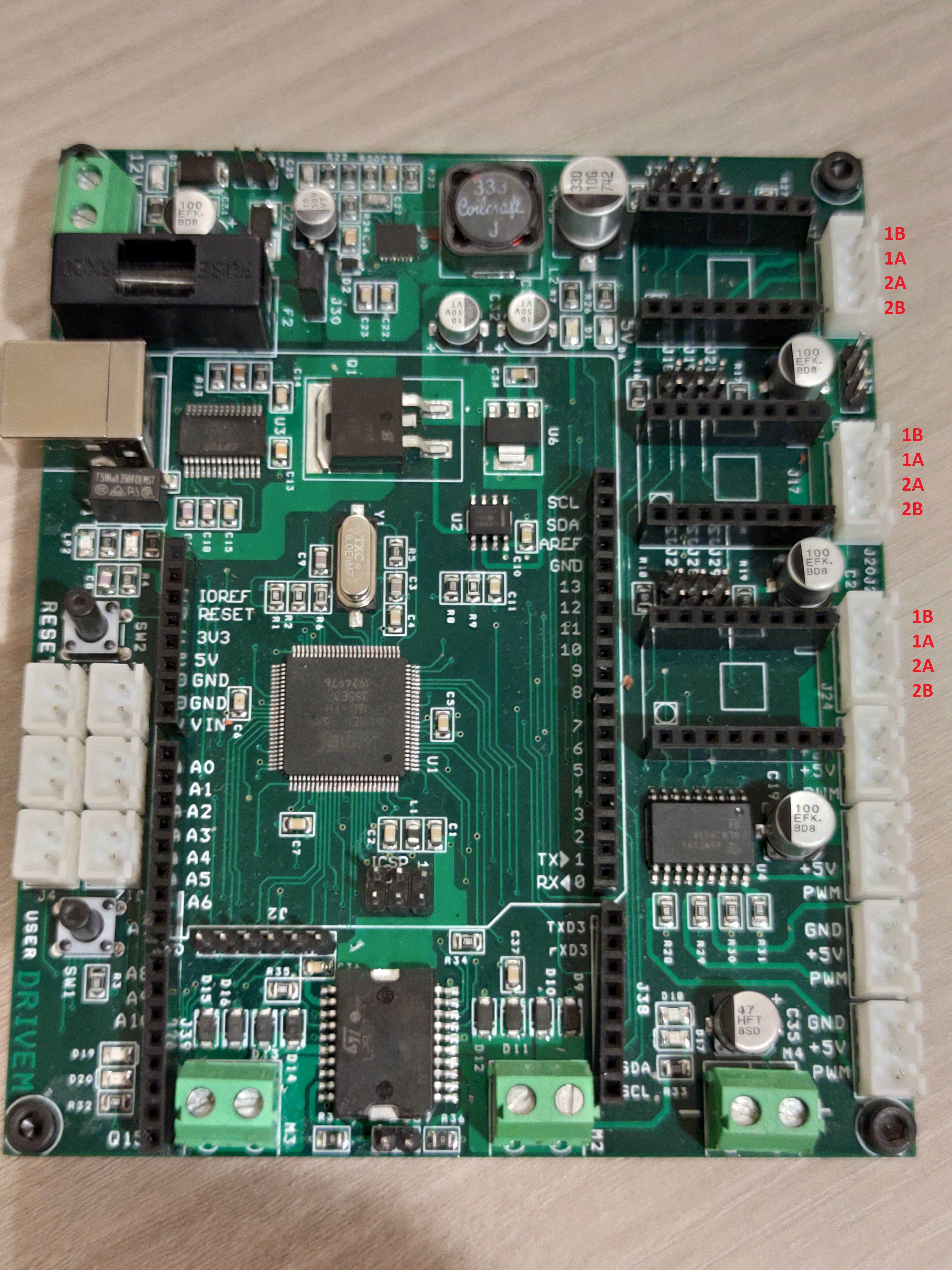
Development of the Drivemall Board
by HorizonLab in Circuits > Arduino
472 Views, 0 Favorites, 0 Comments
Development of the Drivemall Board

In this tutorial we will see the basic steps for creating a custom Arduino board. The software used are KiCad for the board design and the Arduino IDE for the creation and loading of firmware for the board.
Requisiti
Description of the set requirements.
- Control of 2 DC motors
- 3 stepper motor control
- 4 servomotor control (PWM)
- Power management: dual 12V and 5V power supply.
- Compatibility with Arduino UNO and Mega header.
- Header for inserting limit switches and switches.
- Use of the ATMega2560 microcontroller
- Compatibility with the Arduino system by preloading the Arduino bootloader.
Schematic


Creation of the circuit schematic by dividing it into logical areas such as power subsystem, microcontroller subsystem, etc ...
Once the schematic has been created, run the check.
Then generate the files relating to the schematic and above all the BOM file.
Item Quantity Reference Part 1 17 C1,C2,C4,C5,C6,C7,C10, C11,C14,C15,C16,C22,C23, C31,C34,C36,C37 100nF 2 3 C3,C8,C9 22pF 3 1 C12 1u 4 2 C13,C26 4u7 16V 5 2 C17,C18 47pF 6 4 C19,C20,C21,C30 100uF 25V 7 1 C24 330uF 10v 8 1 C25 82pF 9 1 C27 27p 10 1 C28 3300p 11 3 C29,C32,C33 10uF 50V 12 1 C35 47uF 50V 13 1 D1 led yellow 14 1 D2 RB400VAM-50TR 15 1 D3 B360A-13-F 16 1 D4 SS24 17 3 D5,D17,D20 led red 18 3 D6,D18,D19 led green 19 8 D9,D10,D11,D12,D13,D14, D15,D16 1N5819HW1 20 1 F1 500mA MST 500MA 250V 21 1 F2 10A 22 1 J2 HC-06 23 1 J3 USB B 2411 01 SS-52300-001 24 6 J4,J5,J6,J12,J13,J14 XH2.54-2pin 25 3 J7,J17,J24 CON16C 26 3 J10,J20,J26 XH2.54-4pin 27 1 J15 CON3 28 4 J16,J22,J23,J25 XH2.54-3pin 29 10 J18,J19,J21,J27,J28,J29, J30,J34,J35,J36 JUMPER 30 2 J31,J40 CON2 31 1 J37 pinstrip 32 2 J38,J39 CON8 33 1 LP1 LED RED 34 1 LP2 LED_Green 35 1 L1 10uH MLZ2012M100WT 36 1 L2 33u MSS1260333ML 37 4 M1,M2,M3,M4 MORSETTO 2 -5.08 38 1 Q1 IRF9510S 39 10 R1,R2,R3,R4,R8,R9,R32, R33,R34,R35 10k 40 2 R5,R20 1M 41 1 R6 27R 42 6 R7,R10,R11,R12,R13,R26 1k 43 4 R14,R16,R18,R25 4k7 44 3 R17,R19,R27 100k 45 2 R21,R22 249k 46 1 R23 60k4 47 1 R24 47k5 48 4 R28,R29,R30,R31 R 49 2 R36,R37 0R 50 1 SW1 SW PUSHBUTTON 51 1 SW2 SW PUSHBUTTON 52 1 U1 ATMEGA2560-16AU 53 1 U2 LM358 54 1 U3 FT232RL 55 1 U4 ULN2803 56 1 U5 LTC3115 57 1 U6 LM1117-3.3 59 1 U9 L298P 60 1 Y1 Crystal 16MHz
Downloads
PCB Design
Arrange the components within the area chosen for the PCB. (put combined image on page 5-7-9 of "DRIVEM.pdf").
Satisfied with the placement, proceed with the unraveling of the connections between the components.
Check the design rules defined by the company that will produce the pcb.
Generation of the gerber file to be sent to the company.
Possible European PCB manufacturers:
https://www.multi-circuit-boards.eu/
Chinese PCB manufacturers:
Local Fablab can provide access to machines for making prototypes.
Board Assembly and Test


Once the pcb and the components have been received, proceed to assemble the board by soldering the components.
Once assembled, proceed with the electrical tests of the board, checking for example the continuity of the tracks and the correct power supply of the circuits.
Use the Board


Now that the board is assembled and the correct electrical operation has been verified, you can proceed with the use of the board via the Arduino IDE (once the Arduino bootloader is loaded you could refer to the activity on loading a bootloader).