Develop Modeling and Assembly Skills by Modeling a Real-life Expedient Bridging System.
by cbdz0001 in Workshop > Organizing
506 Views, 2 Favorites, 0 Comments
Develop Modeling and Assembly Skills by Modeling a Real-life Expedient Bridging System.

Gateway Community & Technical College (KCTCS) - DPT 100
For my contest entry, I had both a need for developing my modeling skills beyond my experience with traditional AutoCAD software, and for becoming familiar with the project organization functionality of Fusion 360 to facilitate an efficient and logical workflow throughout a project's development cycle.
I thought a system for expedient bridging used by US Army Combat Engineers would be a fun, standardized, and accessibly documented challenge to translate from real-life parts weighing hundreds of pounds each and assembled by manpower alone, into a virtual and accessible 'parts bin' which I could then utilize to efficiently assemble a realistic bridge design.
Supplies
US Army Technical Manual 5-277 (OR EQUIV.) "BAILEY BRIDGE"
(If you are interested in practicing modeling and building such a 'parts kit', the Army has published many Technical Manuals over the years covering vehicles, defenses, and 'constructables' of all kinds (besides bridges.) They are full of pictures and useful data to make research and drafting easier... pick something you might have seen in real life and let your imagination take point!)
Sites for US Army Technical Manuals:
Military Manuals - Archive.org
(Always exercise caution when downloading PDFs!)
Use TM Available Online to Model Individual Parts.

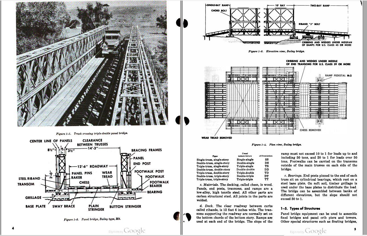
Start with major parts and work your way through modeling each part roughly.
Begin by reading the sections of the TM pertaining to components and assembly (check the table of contents!)
(If you go with something besides the Bailey Bridge system, find the parts of the TM with the most useful info you can of the design in mind.)
Once you feel comfortable identifying what you consider 'core' components - ie. if you chose an M1 Abrams tank, the hull or roadwheels, start there.
If there are any dimensions you can't get from your TM, try an image search online for specific angles or parts of your chosen design. Don't be afraid to make estimates until you find more info - developing your intuition for size and distance is a great advantage for modeling real-life objects and it takes practice!
As you become familiar with the complete, assembled subject of your project, start to consider the best way to organize everything as you work on the first parts, in a way that makes everything as accessible as possible to find. When you're attempting to model an existing object or assembly you're not intimately familiar with already, working through a few parts before really defining the organizational structure of your Fusion 360 Project can give you a chance to make a better assessment of those needs.
Utilize Fresh Workspaces and the Data Panel to Begin Assembling Parts.
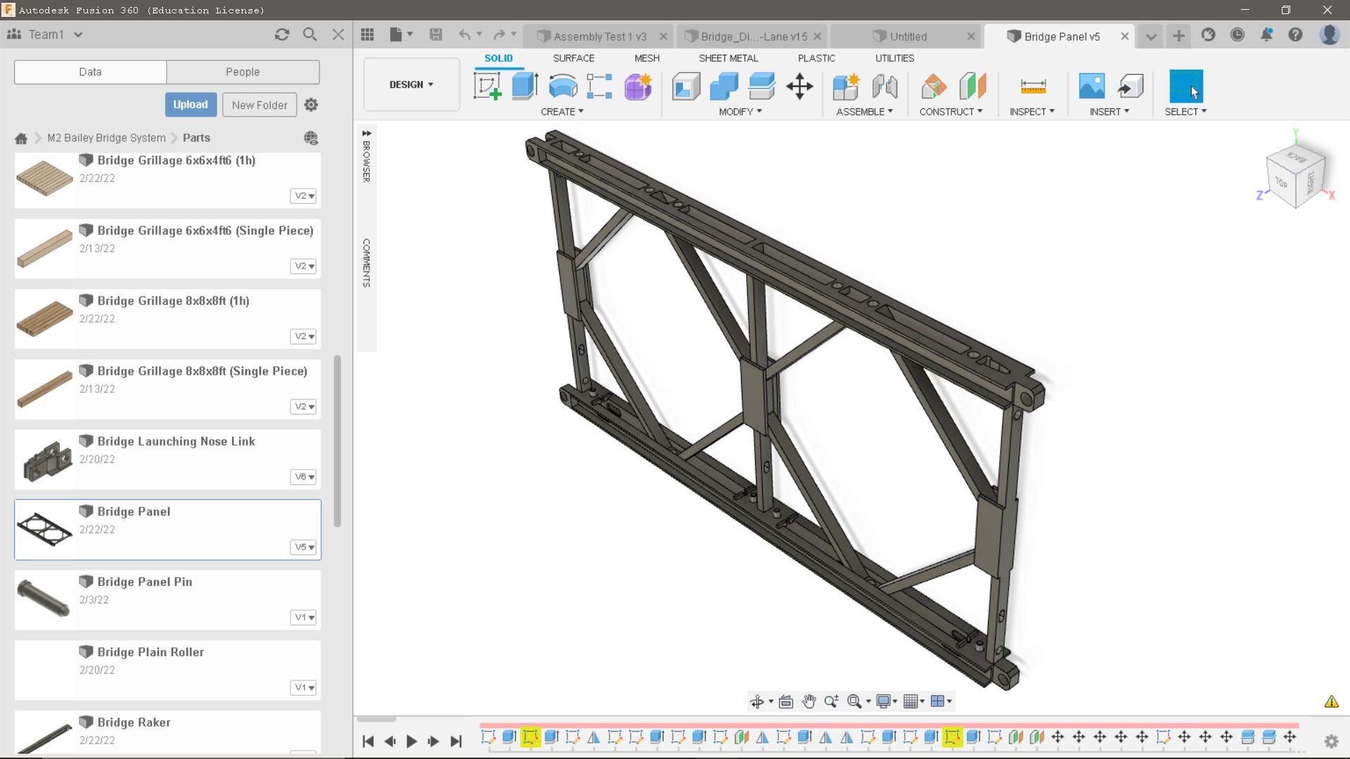
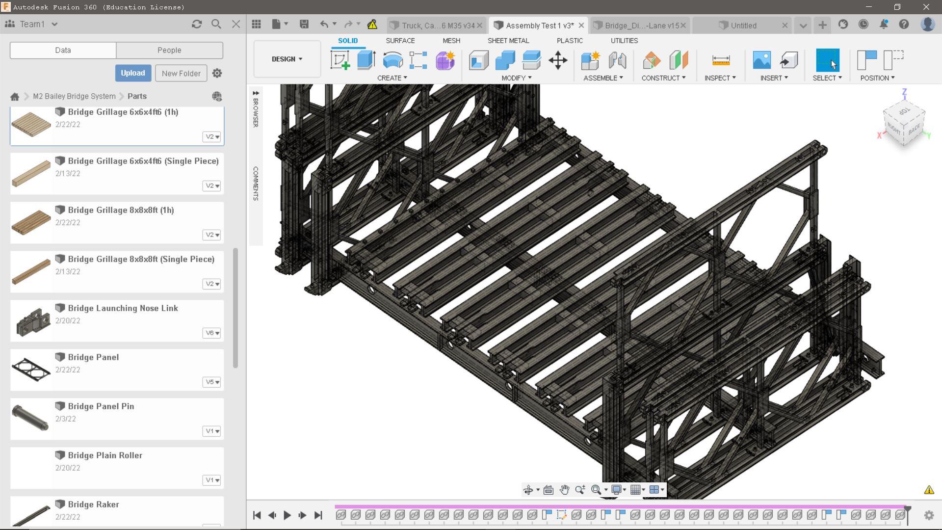
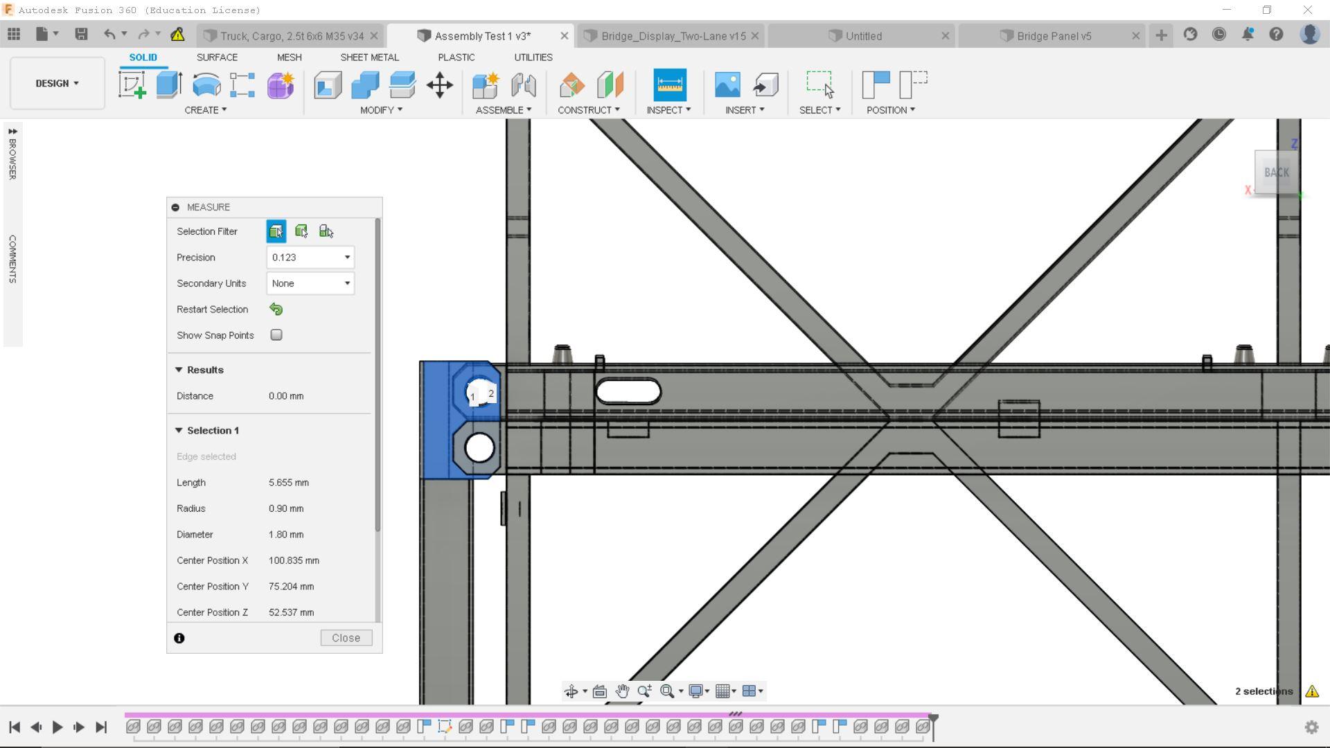
Once individual parts have been modelled, you can make smaller assemblies to test fit parts and provide a useful space to utilize orthographic views, measuring tool, etc to get things lined up.
Start with some of your 'core' components, and fit them together carefully using the different Move/Copy commands, Align, etc.
It's very important to consider a logical order for this process - picking the most ubiquitous and central components with the most overall interaction with other parts is critical. If this doesn't happen, you will find that down the road when you're working on incorporating minor/miscellaneous parts that don't fit right, making adjustments to mounting points or connections will throw a lot of things out of whack that you've already modeled in an unpredictable way.
This is the step where project management and workflow really become important, especially if you are attempting something with lots of parts and assemblies you want to keep organized. The organizational function of Fusion 360 is definitely not the flashiest feature of the software, but it is an unspoken hero in getting the job done successfully.
Using the 'Data' panel accessible from the button in the upper left corner of the screen, click 'New Project' if you haven't already done so, and define the structure of your project via folders within. I went with "Parts" and "Assemblies" because it was manageable for the Bailey Bridge, but you should consider the scope and size of your project to determine what works for you. It's all about being at the helm of a project cycle and developing your workflow methodology!
As your objectives mature, adapt your Project structure. For example, when it came time to try printing some bridge system parts I modeled, I created a separate folder for the slightly modified versions of each part that were optimized for 3D printers. Make an effort to stay organized as your project expands.
Collaboration is something you may run into at school or in your career, whether as a team member or a leader. Either way, having practice with these concepts in advance is a huge help!
Throughout this process, pause and consider each decision you make about how to proceed as if you're leading a development team. Think about the intent and the execution of each action. Will it cause conflicts with other actions or revisions that other team members might be tasked with at the same time? Would your fellow team members be able to clearly understand your intent? Even if you never work in a team environment on a project in your life, applying this concept to your individual projects will keep them better organized and your project's life cycle more efficient.
The Big Picture...
Utilize your assemblies and a new space to build a bridge! (or whatever you picked!)
This is it... the neat thing you thought would be a fun challenge to model in Fusion 360 is about to come to life!
At this point, you should have all of your necessary parts modeled and test-fitted thoroughly. Now is a good time to consider creating 'sub-assemblies' of the finished product based on what you're making. IE - if you modeled the parts of an Abrams tank, you might want to have the turret parts assembled and save them as a whole assembled unit.
In real life, this is a big part of organizing the development and manufacturing process.
Consider the development of a new car - the design team might have several wheel and tire combinations that they want to be included depending on the place a specific advertisement might run. Generating a new drawing or render is as simple as switching one wheel/tire sub-assembly for another. Getting in the habit of thinking about this is critical for anyone with an interest in design or project management.
If you're confident your parts are accurately dimensioned, and you're comfortable with your organization so far, enjoy your hard work and create. Imagine you're doing it as a professional, for potential clients or customers - put your best effort into it!
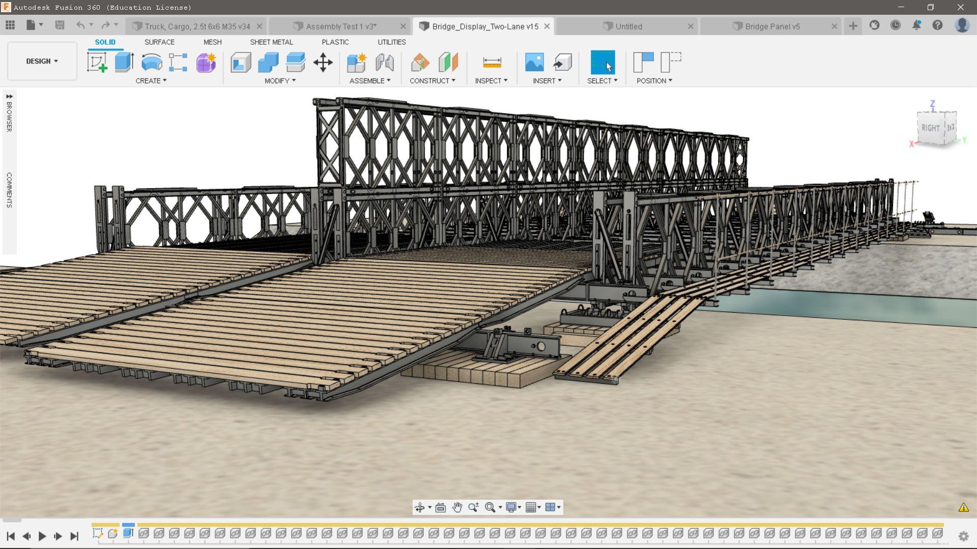
Create an environment that facilitates displaying whatever features or profiles you think look best on your chosen subject. Making a bridging site was as simple as sketching a big rectangle a few hundred 'feet' in each direction with a big gulley in the middle, and then extruding it across the origin. I added some 'water' and a couple of sand/dirt textures to add a little realism. This should be tailored to your subject for maximum visual impact to anyone who might look at it. If you want to display an Abrams tank you modeled for a project, you might choose to mock up a little section of roadway or a defensive position in which to place it.
When you're on this step, you may find yourself using a large environment in the model space. A few things you might find helpful working on a big assembly:
- Depending on your computer and the amount of complexity of your parts, you will reach a point where things sloooow down and moving the camera position or a part can generate a lot of lag. ADJUST your graphics settings as you go to keep your assembly process going smoothly.
- You may notice the things in the environment you're creating acquire a grayish hue at a certain point or from certain perspectives. This could be the Layout Grid, and occurs when there are a lot of interval marks on screen and too close together to distinguish individually, such as when you're zoomed out and looking at a few hundred or thousand at once. TURN OFF THE LAYOUT GRID in the toolbar at the bottom of the workspace or adjust the number of incremental marks as needed.
- If you decide to make some terrain to build your final assembly in/on, don't forget to USE THE SELECTABLE/UNSELECTABLE option in the right click menu of your components/sub-assemblies, so you aren't constantly selecting your background and scene objects while you work on assembling. Also, use the Ground Plane Offset option to position the XY origin plane directly over the 'ground' of your environment.
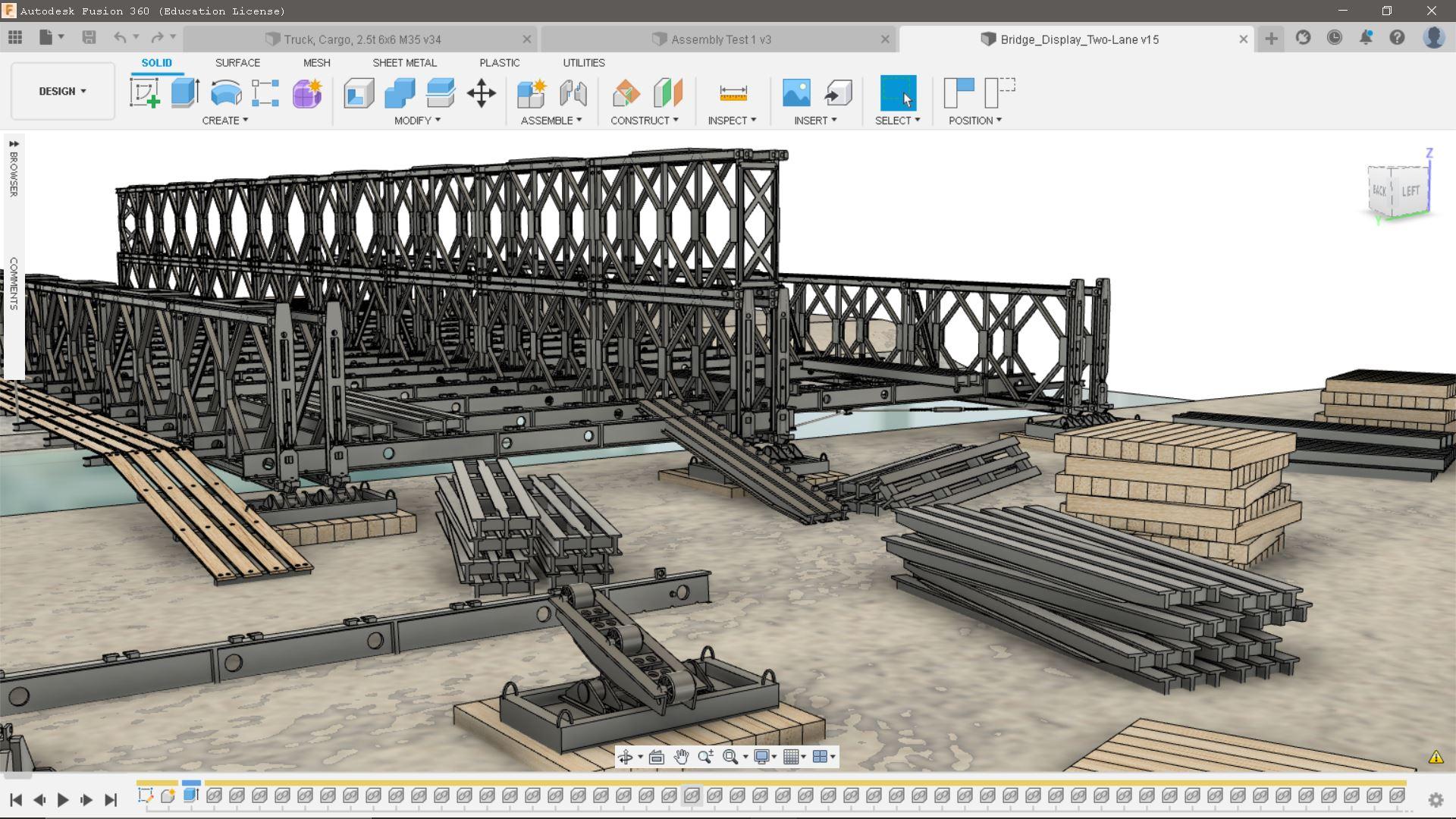
- IMAGINE YOU'RE THERE! What kinds of objects would you expect to see that might add to the impact of the display? Maybe you're working on the firefighting drone system of the future one day - would the depiction be enhanced by it being seen next to an everyday fire hydrant to convey a sense of scale and purpose to the audience? When we built these bridges in the Army, there was a very hectic assembly site full of stacks of parts and people moving them to and fro, so I added some stacks of parts and a few in different stages of assembly at one end of the bridge to highlight a major aspect of the system in use. BE CREATIVE!
HAVE FUN! ENGINEERS CLEAR THE WAY!