Determine Resistor Values by Selecting Colors
by cristinepotu7171 in Circuits > Arduino
651 Views, 4 Favorites, 0 Comments
Determine Resistor Values by Selecting Colors
In this tutorial we see how we can build a resistor value calculator by reading the color code. A project with Arduino or ESP32.
Supplies

.jpg)

.jpg)
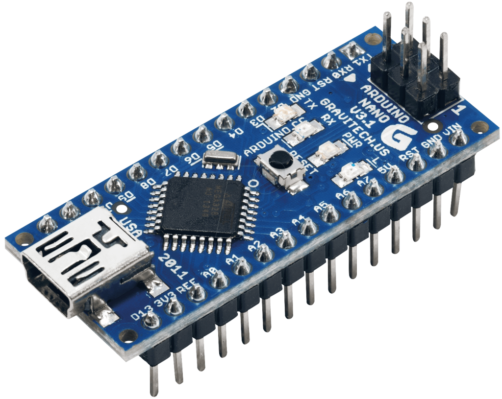
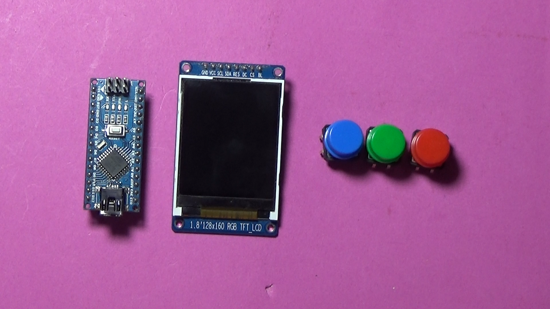
1.Arduino Nano or
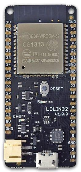
2.ESP32 WEMOS lolin
3.ST7735 display
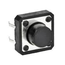
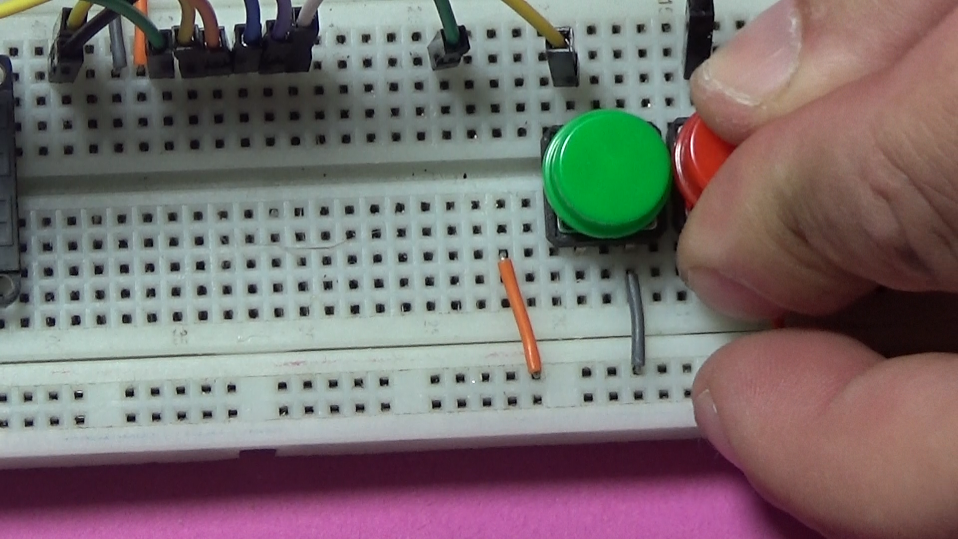
4.push button x3
5.Visuiono software or
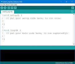
6.Arduino IDE
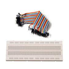
7.breadboar and jumper wires
Schematic Diagram
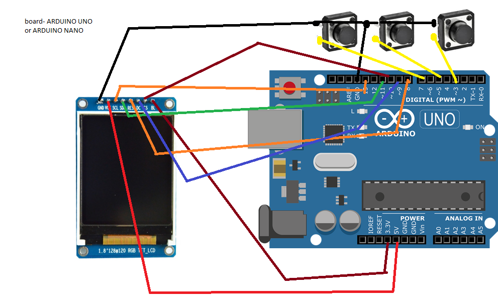
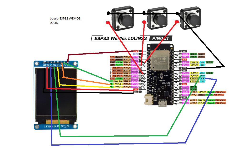
Make the connections of the components according to the diagram below.Attention:a schematic is with Arduino, and the other for ESP32 depending on which option you choose.
Construction
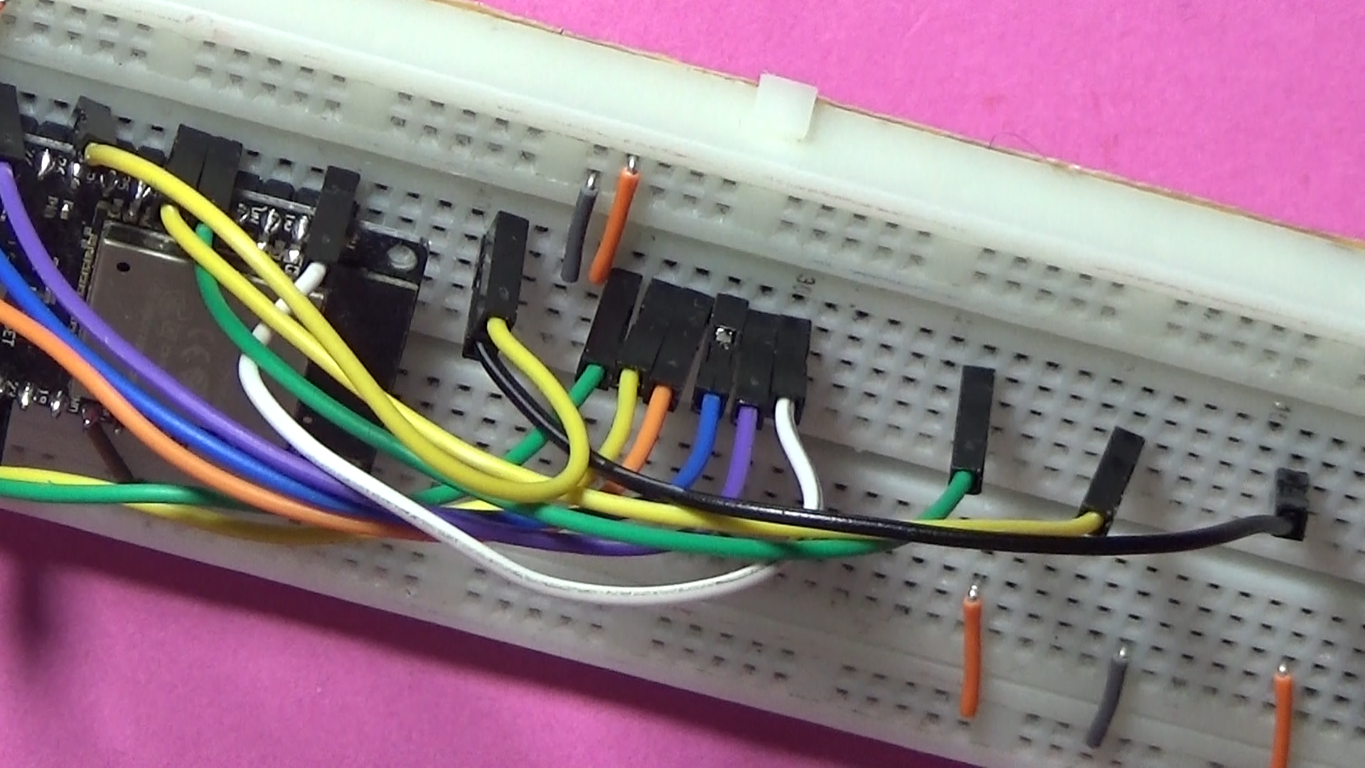
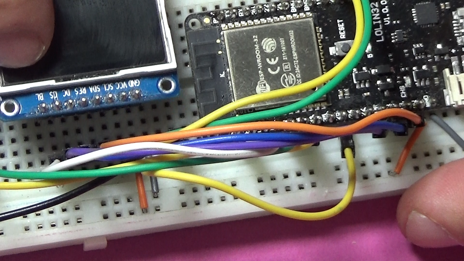
In this stage of the project, we connect the components strictly following the electrical diagram. The construction is particularly easy, it does not require more than 10 minutes.
Software: Upload the Code in Arduino or Esp32 Variant
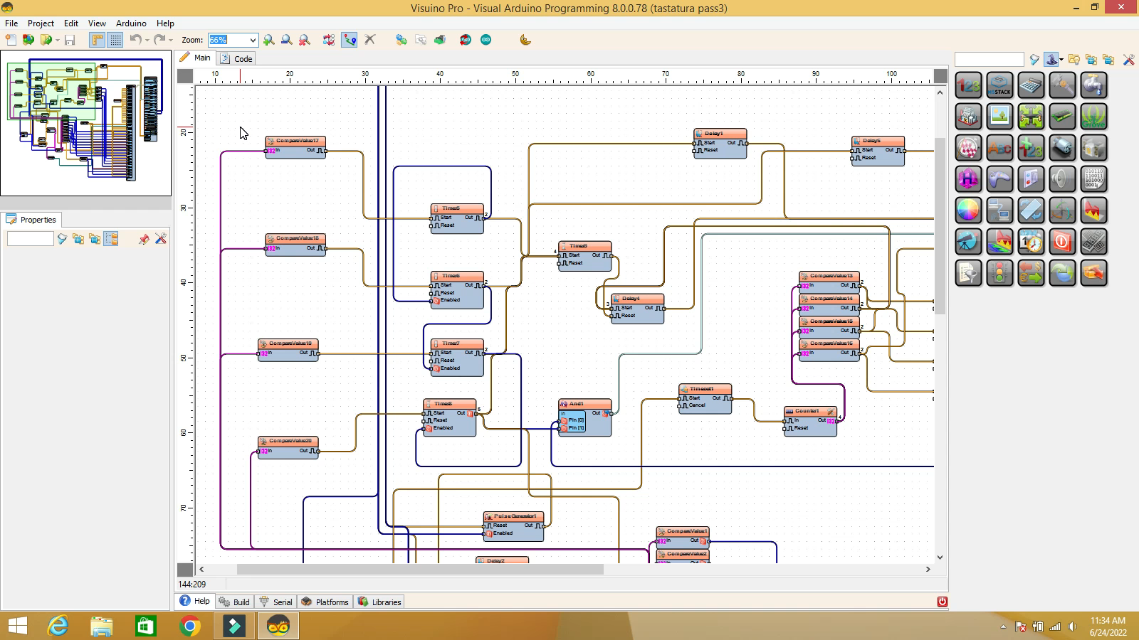
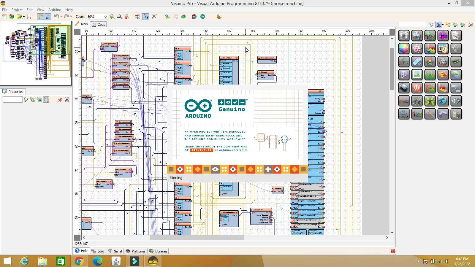
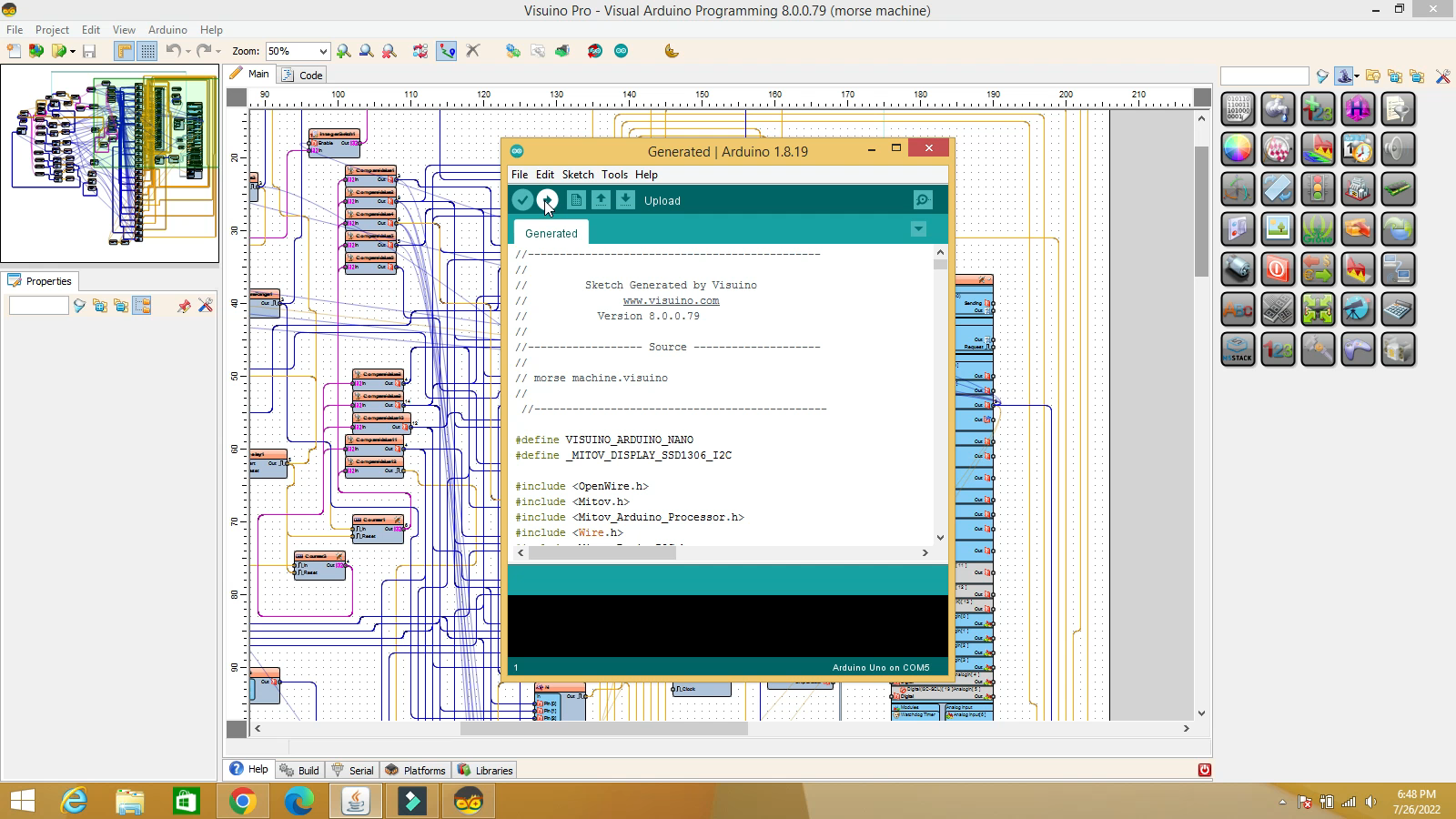
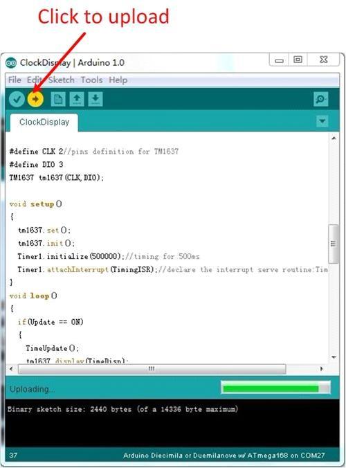
In this step, we upload the code to the Arduino or ESP32 board, depending on the options. Also, you can use the code in Visuino or Arduino.IDE format, as you wish. For Arduino IDE, in Visuino, click on Arduino-Send to Arduino IDE at the top right
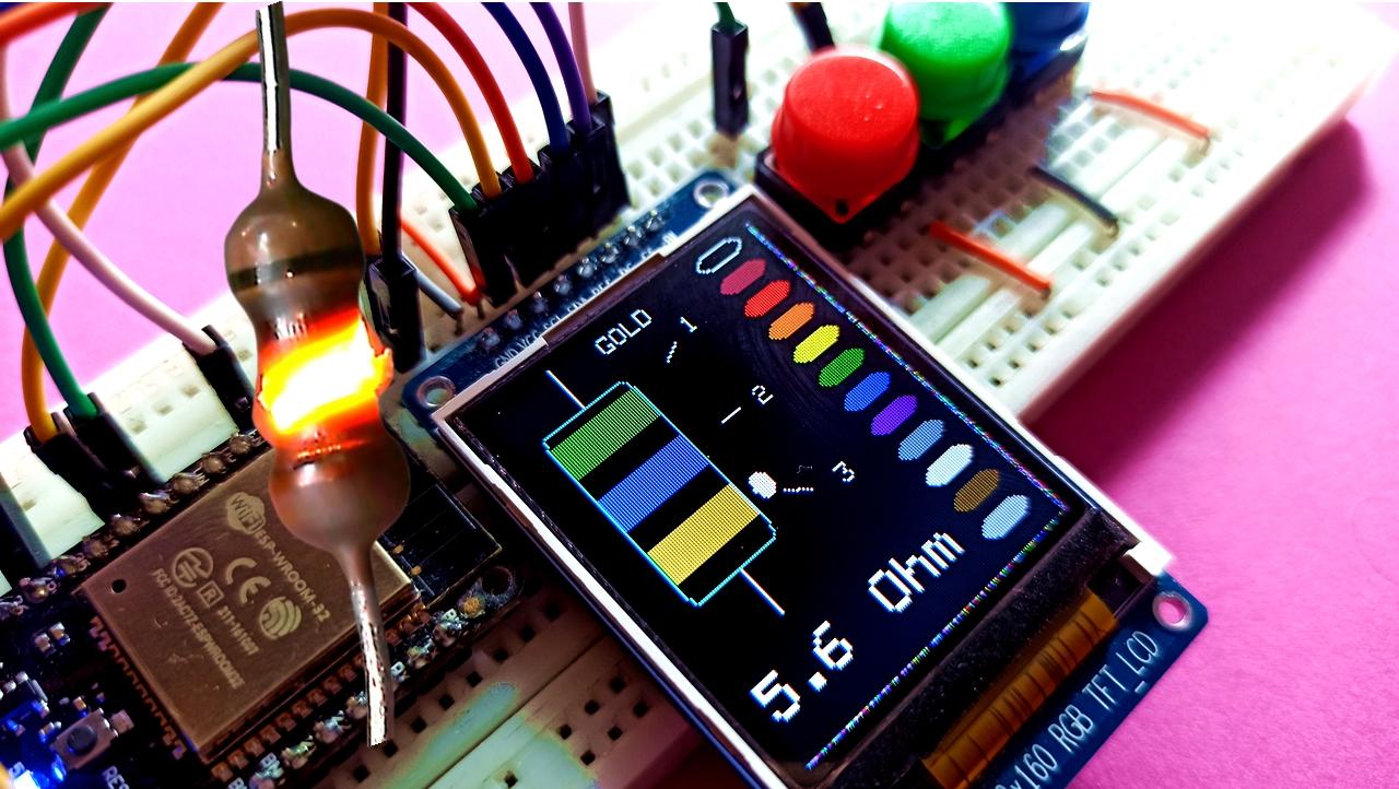
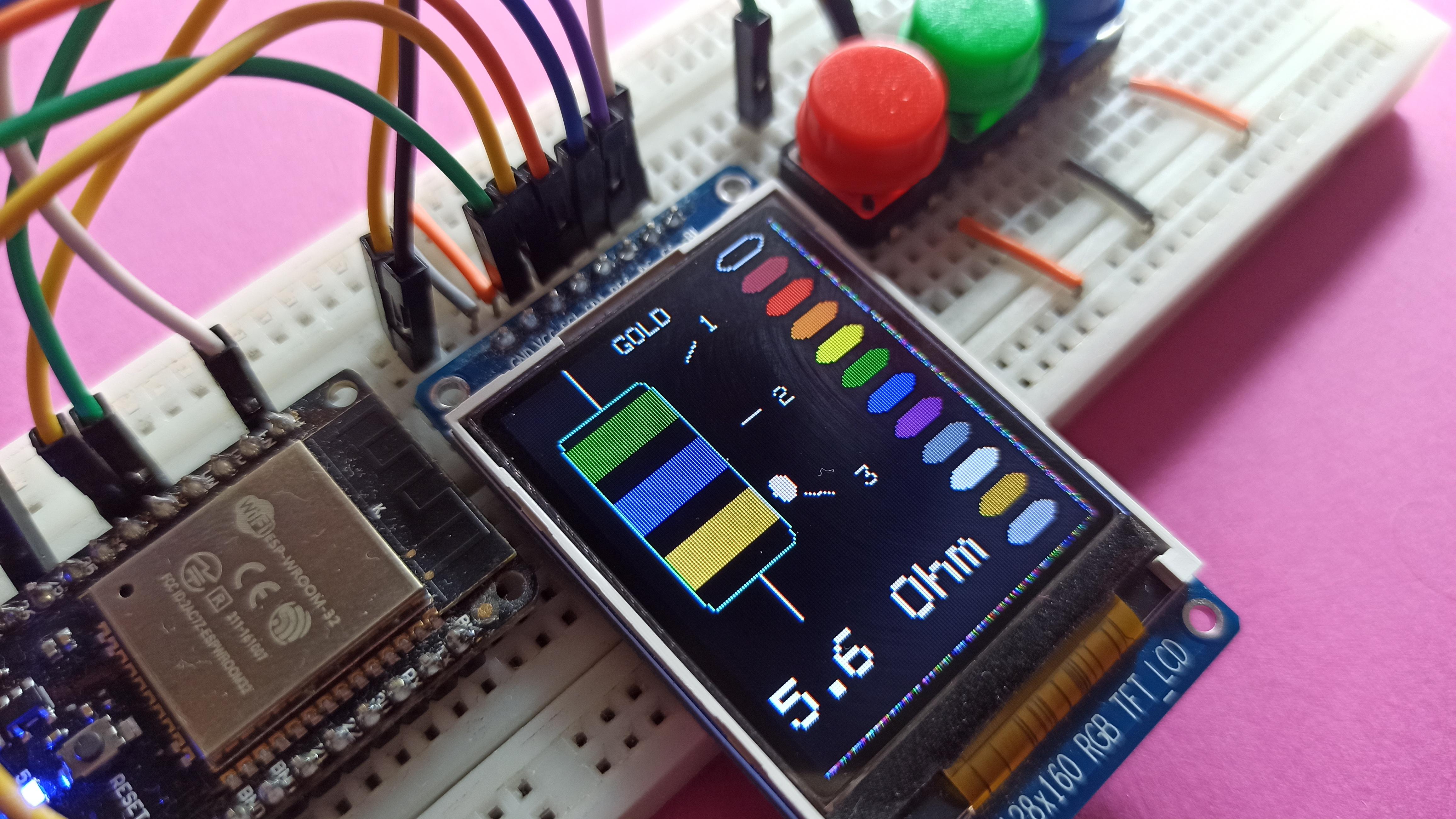
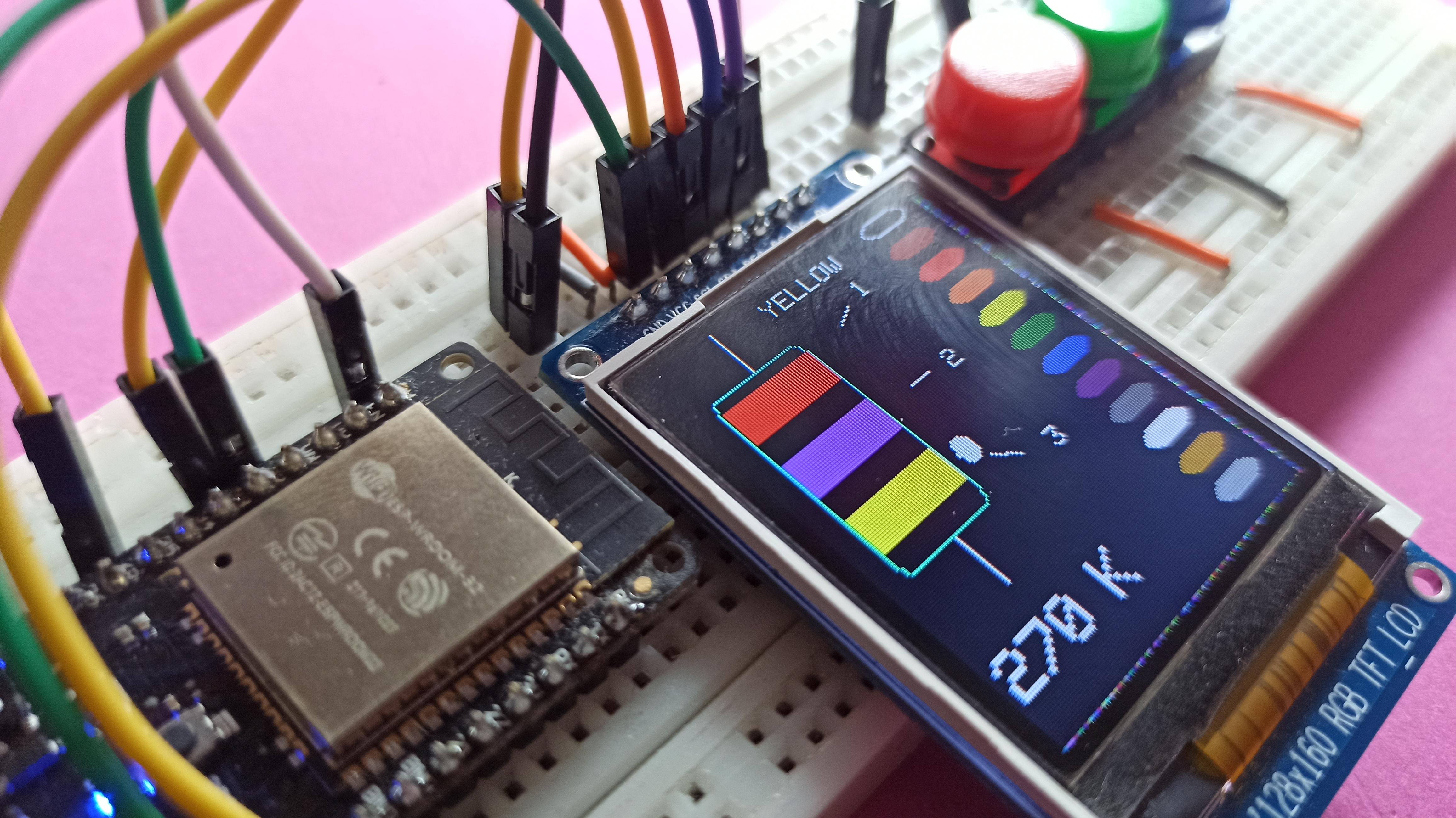
Start the Device
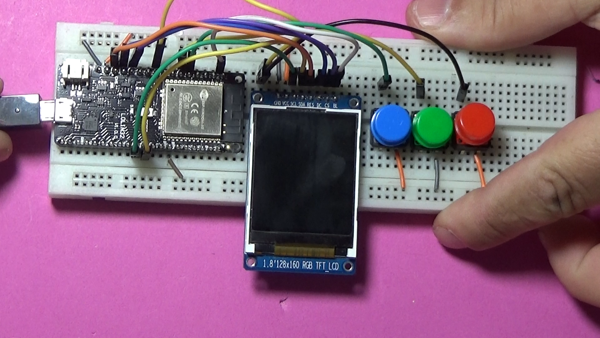
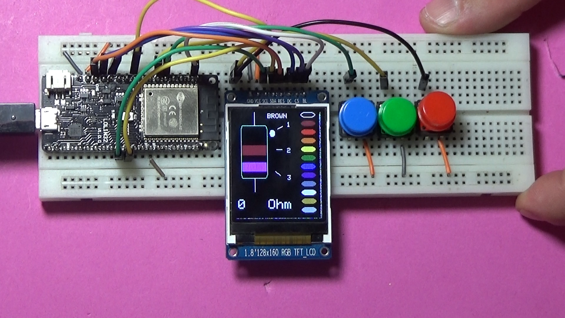
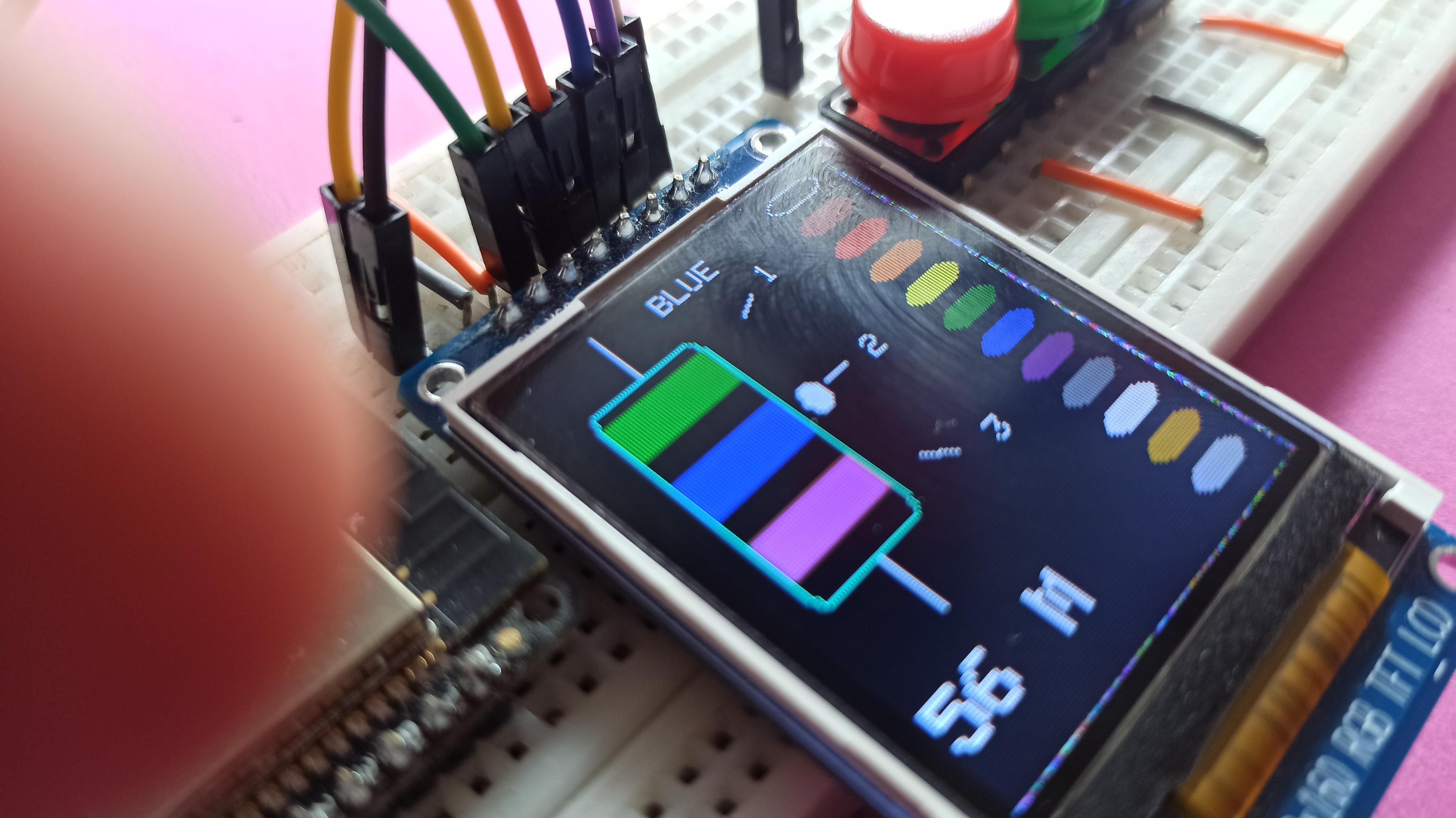

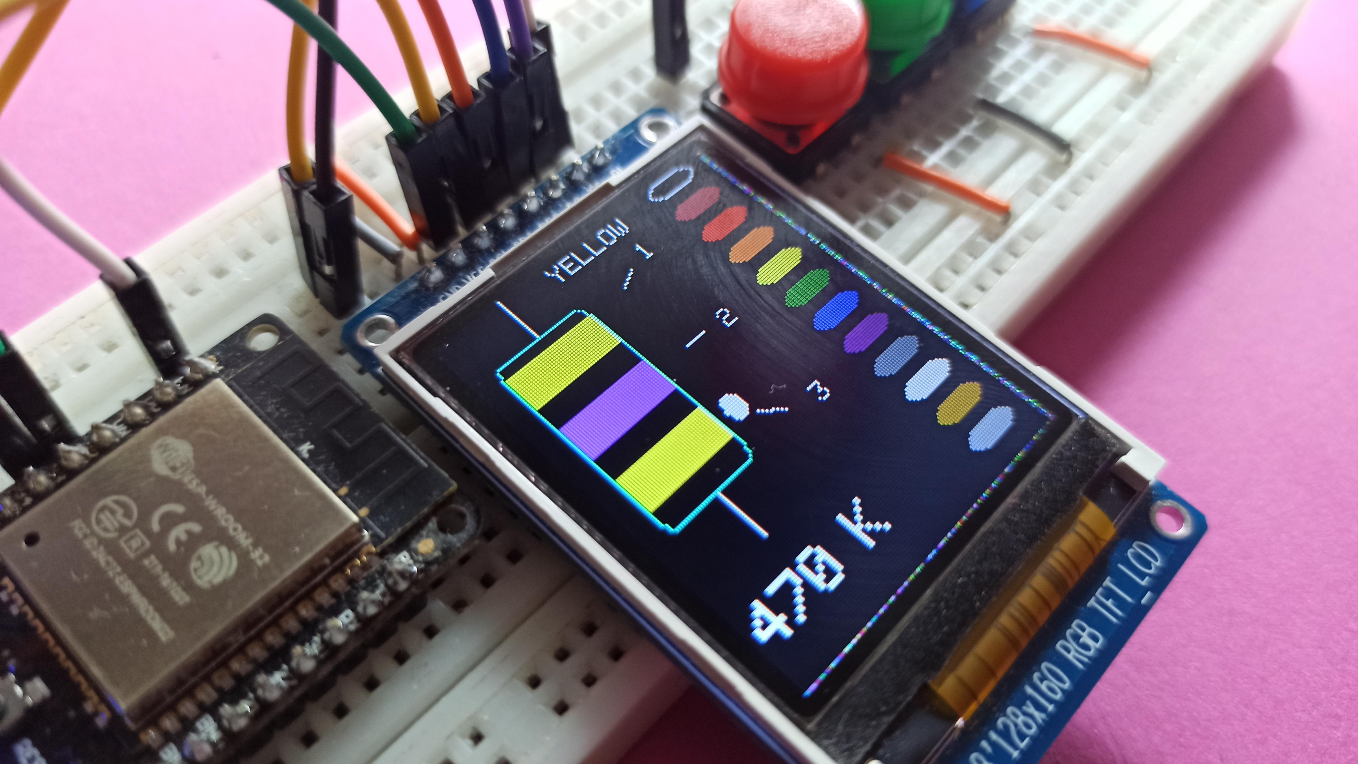
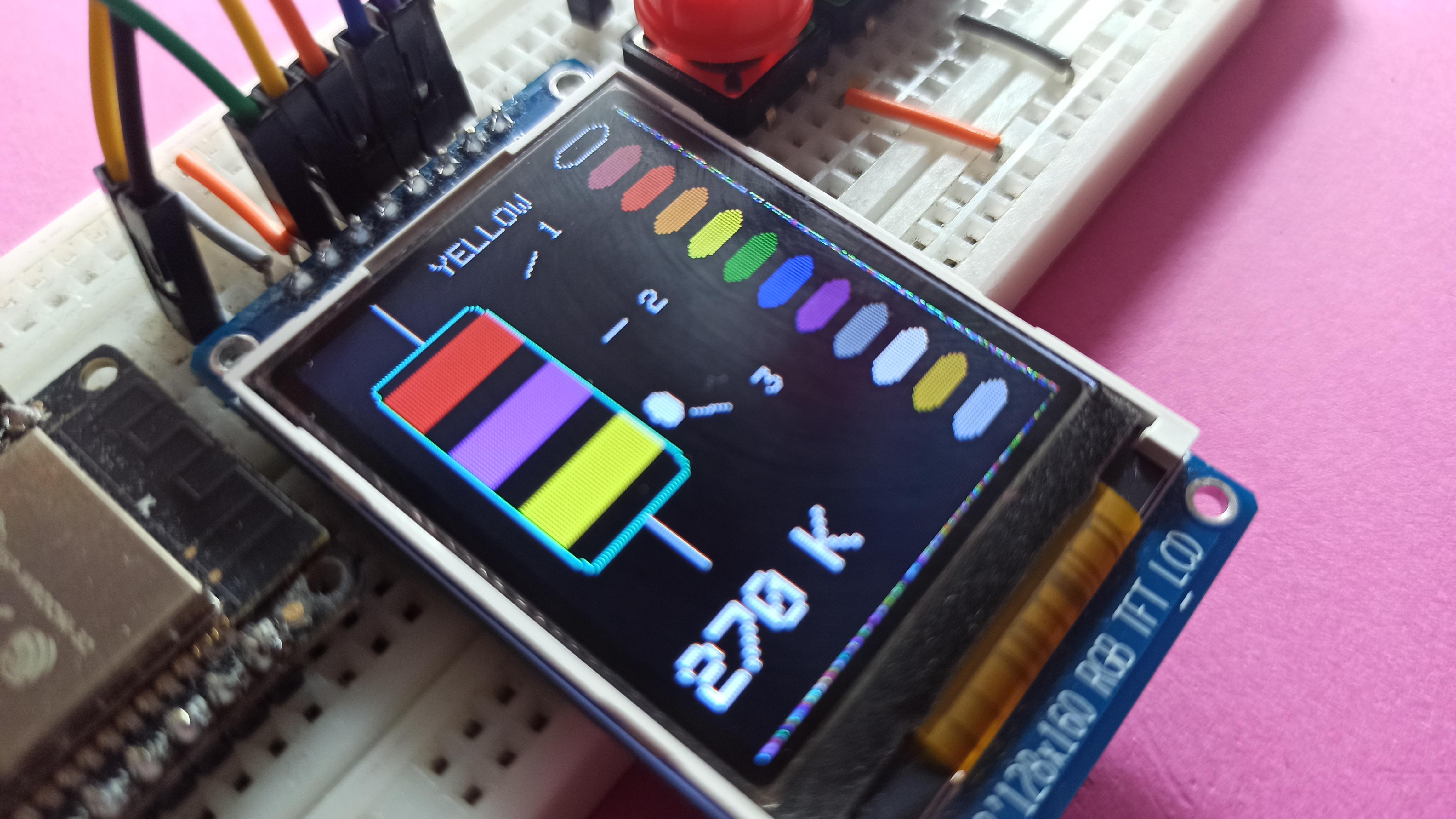
We connect the USB cable to Arduino or ESP32. A resistor with 3 color rings will appear on the display. .select the color from button 1, select the ring from button 2, and when button 3 is pressed, the value of the resistor will appear. I hope you liked my project, if you have any questions you can put them in the comments section. Good luck everyone!