Desktop Pantograph for Text & Drawing
by AjarDesign in Workshop > Laser Cutting
2607 Views, 27 Favorites, 0 Comments
Desktop Pantograph for Text & Drawing
I'm a 20yo University student currently studying at University of Melbourne. As such, I often find myself having to replicate complex text/equations and diagrams whilst completing problems for my study so I can properly annotate, label, and just get a better sense of the problem. Often these are small pictures out of textbooks or printed sheets and get pretty tedious to replicate since I like to work with pen and paper and can't just zoom in.
So, when I saw a video of a metal pantograph being restored, I instantly wondered how I could put the same mechanics into a desktop writing tool for my study, and this is what I created. Using laser cut MDF and some basic calculations, I created a minimalist and useful desktop pantograph that's great for my applications as well as many more. The pantograph is fantastic for graphic design and technical drawings where text needs to be scaled uniformly or small designs enlarged.
Supplies
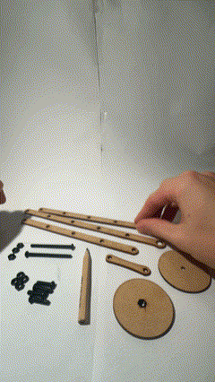
Materials
- 3mm MDF
- M4 hardware
- 4x 16mm bolts
- 3x 5mm bolts
- 14x nuts
- Standard pencil
- Craft/Super Glue
Tools
- Laser Cutter
- Calipers
- Box cutter / hobby knife
- Vice (helpful)
Software
- Fusion360 (free for students!)
- CorelDraw (or alternative for cutter gcode)
I'm using a laser cutter for precision and convenience, but this really isn't necessary equipment to create a similar model. You could achieve something similar with a drill and hand saw using the same piece templates.
Understanding Pantographs
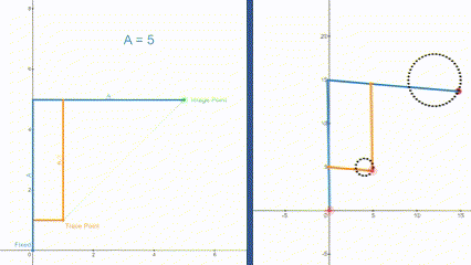
Pantographs are fantastic devices that use the most simple geometric principles to scale up or down text and shapes. A simple pantograph such as the one I'm making, is basically just a linkage with four links with hinged joints, and one fixed point. By using simple triangles, the path followed at the trace point, is directly replicated at the image point although with magnitude in all directions scaled based on the length of the major links.
To make this scaling easy, we keep the fixed point and trace point as opposite vertices on a unit square. Then, the length of the longer links (A) relative to the unit square is the factor of image enlargement. The first GIF above shows how we can create a larger image without moving the trace point. The second GIF depicts how the movement at the trace point is replicated albeit larger at the image point!
To better visualize the dynamics of the pantograph, I first made the two animations using the graphing calculator Desmos above. This is a simple way to make simple geometric reference animations and I have attached the link to them below:
Scaling GIF - https://www.desmos.com/calculator/imendln7b4
Tracing GIF - https://www.desmos.com/calculator/7pukoe5qhr
Dimensions & Planning
The beauty of a pantograph is that the subject you trace can basically be anything, including the results of previous traces. This means that even if you want to scale by four times, you can achieve this by just scaling by two times twice as well, although this will be more time and resource consuming.
However, due to the basic geometry of the pantograph - it should be pretty easy to make this adjustable so that we can combine smaller scales to make larger ones. For this reason, I chose a maximum ratio of 1:5, with free holes such that anything between can also be done. As this includes scale factors of 2, 3, & 5 the first few prime numbers, they should be able to be combined to achieve pretty much any scaling that's desired.
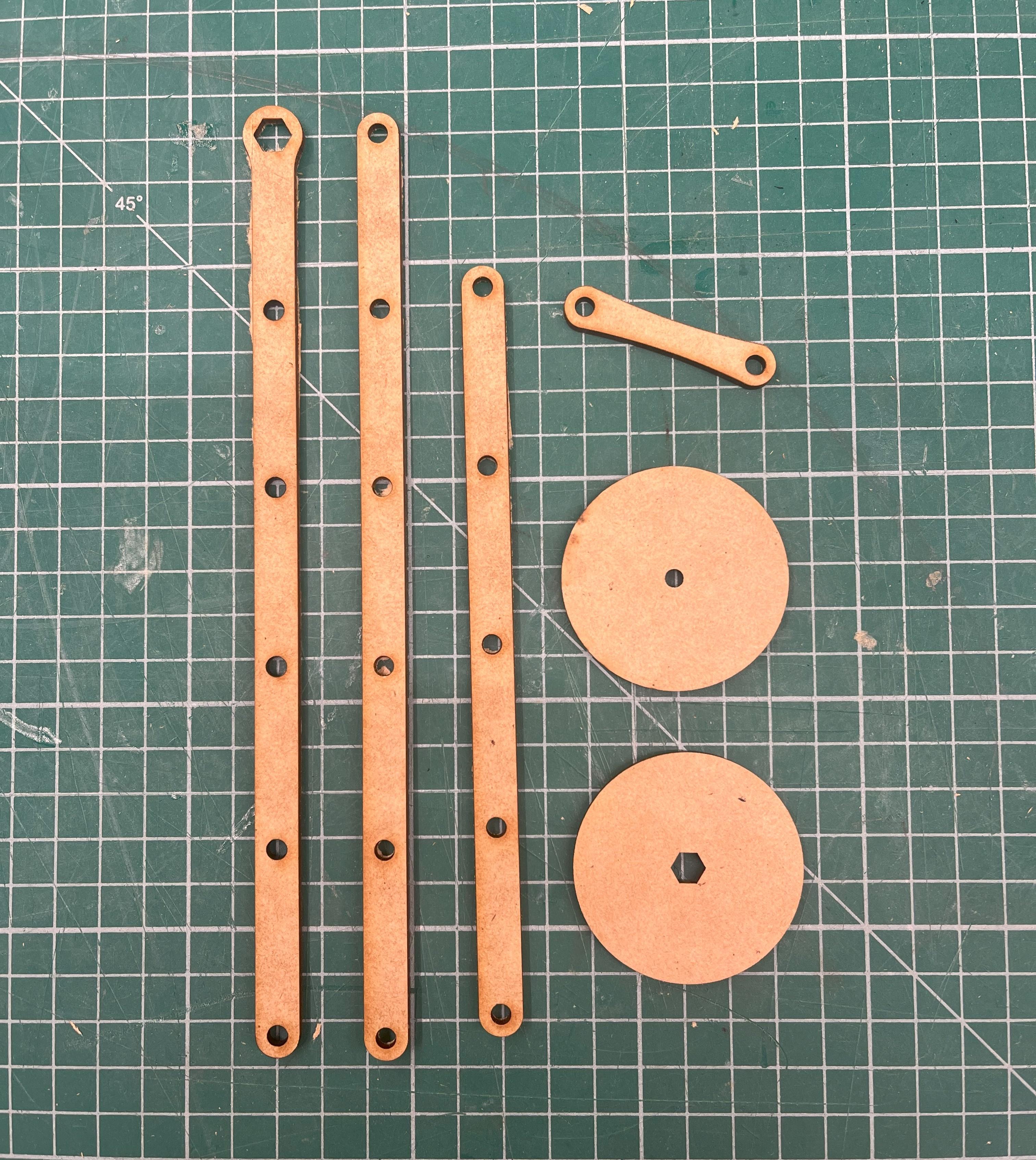
Creating CAD Sketches
Since these parts are all relatively simple, all that needed to be modelled were some simple 2D sketches. For the arms, each has a 4mm hole to match the hardware at intervals of 40mm.
All of the sketches are attached here if you would like to use them yourself, just note you might need to change the pencil holder to fit the pencil you plan to use.
Export Files
Exporting files for laser cutting is really easy in Fusion360 - just right-click each of your sketches and select the "export as DXF" option. My files above are already in this format so no need to redo this if you're using them, only if you make your own from scratch.
Laser Cutting Parts
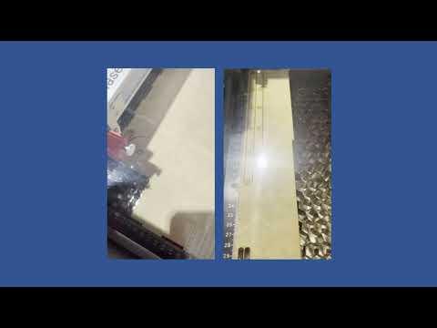
Once you have your completed DXF files, you're ready to set up for laser cutting! As with all my projects I used a Trotec laser cutter for this, so the process was as easy as importing my selection into CorelDraw on the connected computer – and then printing the page to Trotec Job Control.
Once it's all set up on Job Control all that's left to do is let it run and enjoy watching!
Clean Up
After laser cutting sometimes the parts can have a little bit of leftover material where the laser didn't cleanly cut through. This is easily fixed by taking some time with a blade and shaving off any excess along the edges of the part. If your cutter is well set up this shouldn't really be an issue but if there is any of this excess it's easy to clean up.
Part Prep
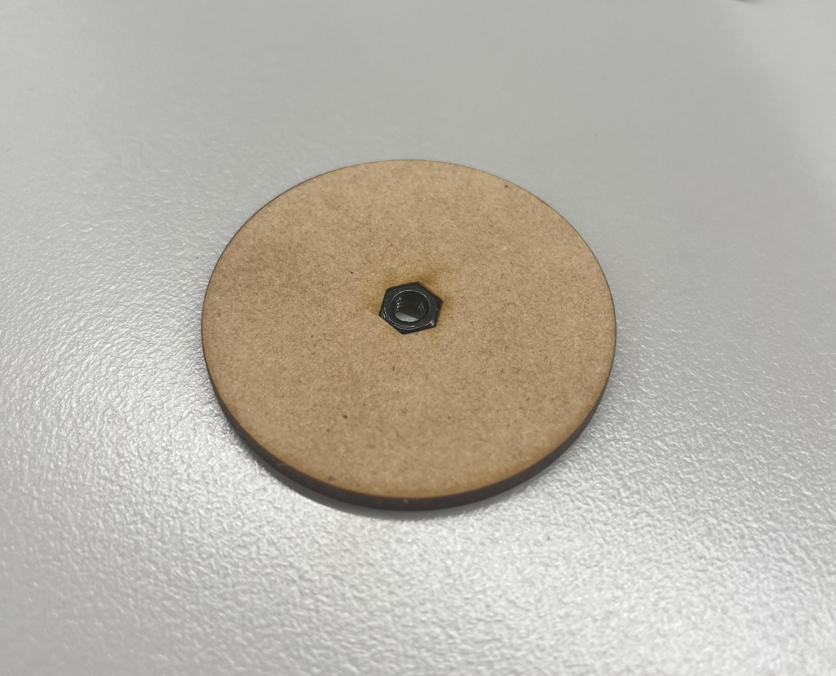
There are a couple of parts that need some extra preparation before we put it all together - namely the base part with the nut insert and a nut to the arm so we can secure our pencil.
For the nut insert, the laser cut tolerance was perfect for a very snug press fit in my case. I used my calipers to measure the nut size and then designed the hole dimensions to match. A small amount of extra material will be taken off due to the thickness of the laser, however, in my case this was the perfect amount of leeway I needed for a nice fit. Then the nut was pressed into place using a small vice - but this could just as easily been done with a hammer or even probably by hand.
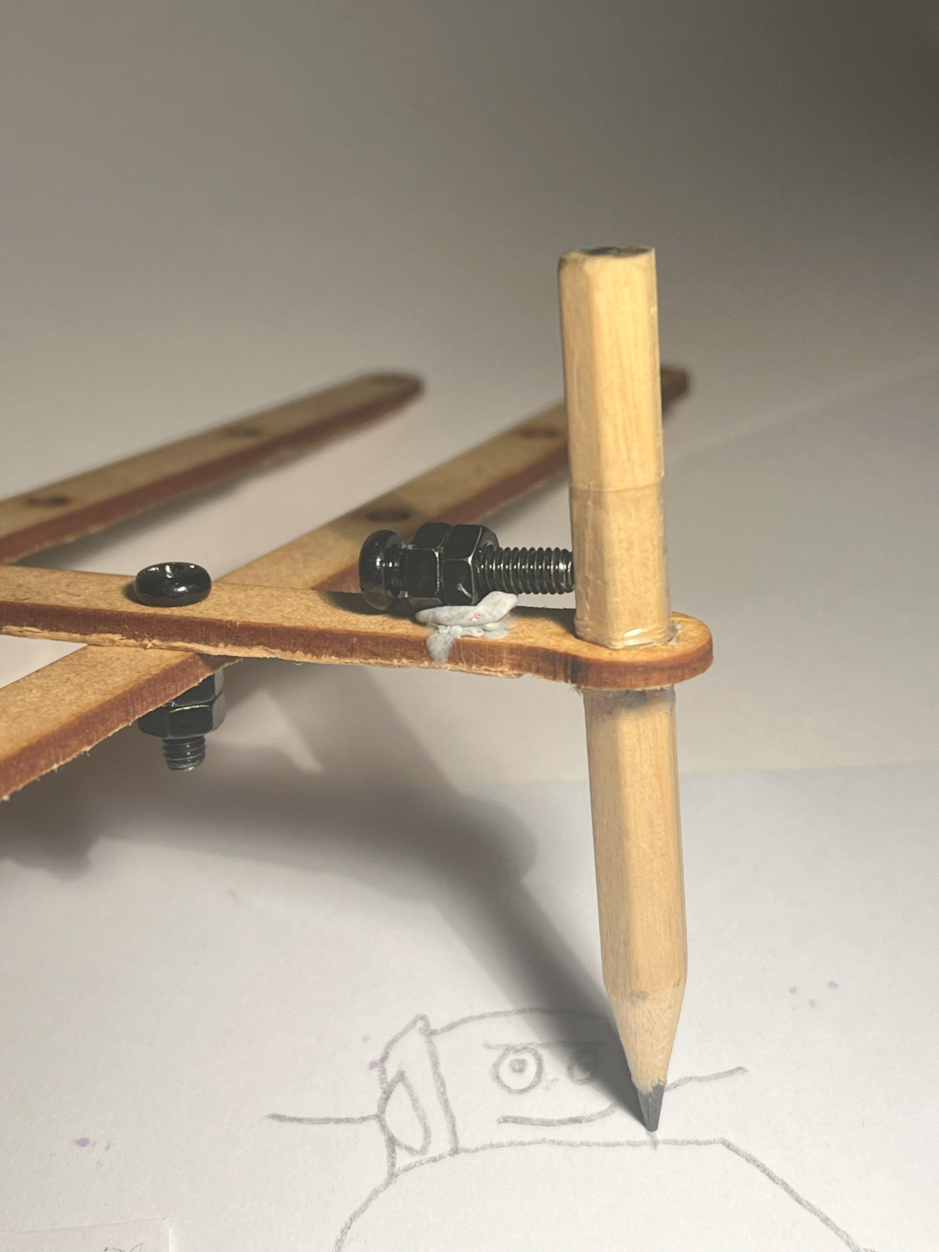
The other piece that needs some prep is the long arm for the pencil - for this one all we need to do is glue on a couple of nuts in line with the pencil hole so we can thread a bolt through them onto the pencil just like a set screw. I used two nuts since they're quite small and to make sure their threads would be in line I put a screw through them during the glue up.
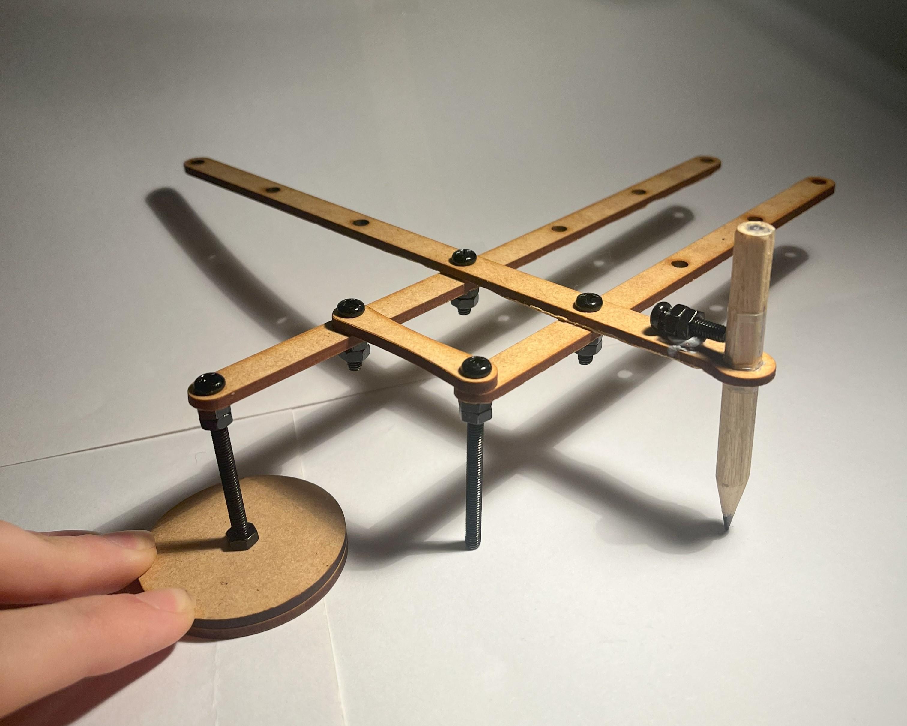
Construction
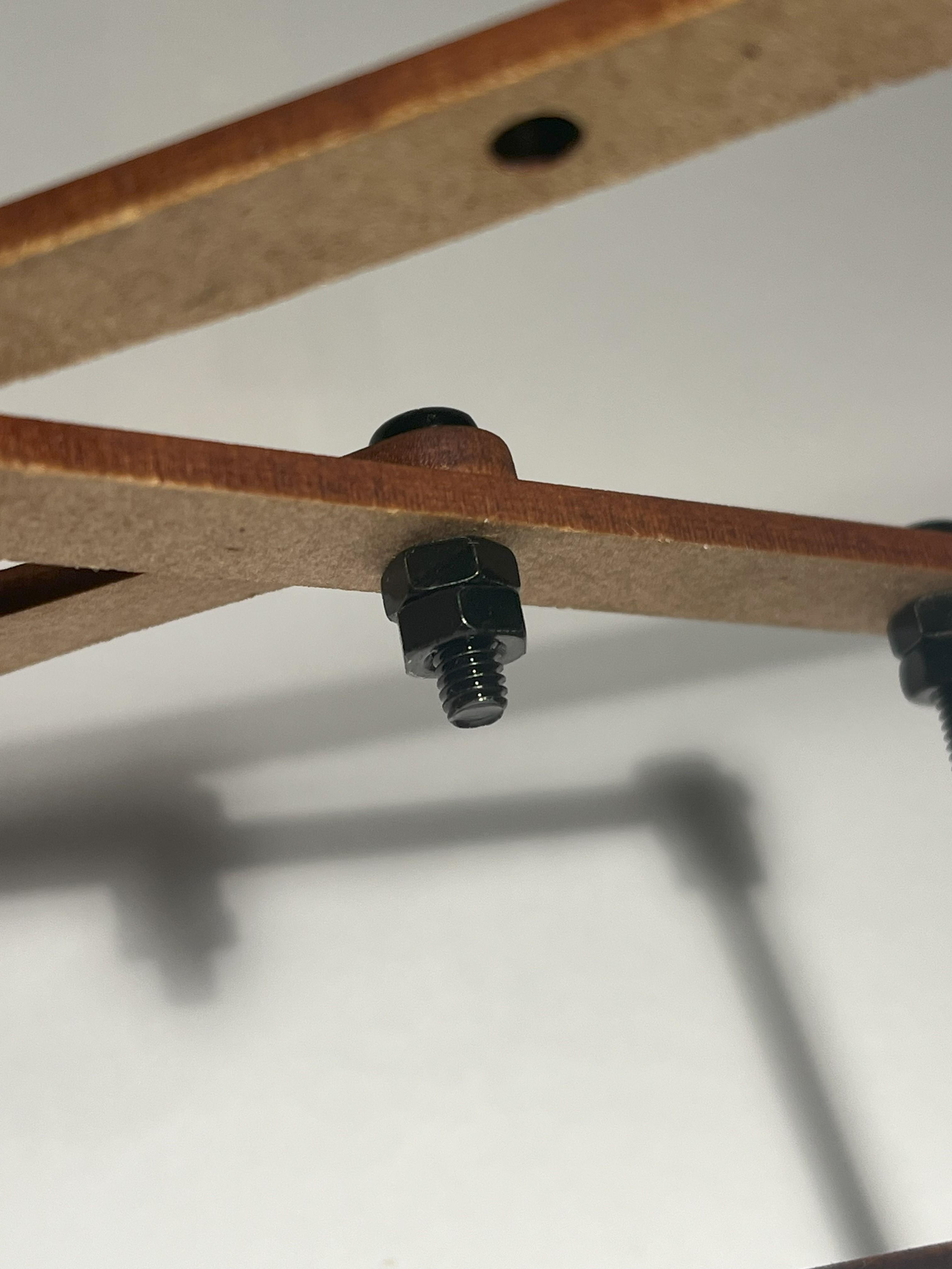
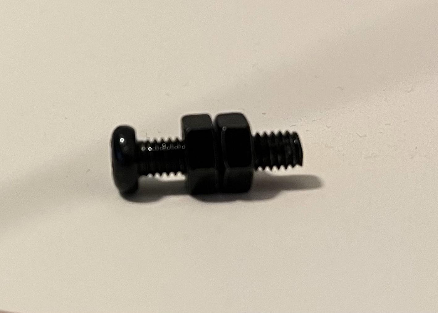
The whole system goes together pretty simply, just layer each of the beams and attach the joints with the smaller nuts and bolts. All of the joints should have two nuts tightened together on the underside as this will prevent them from coming loose during use.
The stand uses four nuts - two nuts to support the underside of the beam, one which goes above both base pieces, and the last pressed into the lower base piece.
The pantograph can be easily adjusted through any of the precut holes. The device will work fine to scale the piece so long as the fixed point, trace point, and image point are all along the same line as each other - this is like moving the tracing arm down and over by one notch.
Lastly, the pencil just slips in and is secured with the set screw so the height can be adjustable. Further, the height of the trace point can be adjusted as well. To do this just put a nut on the bolt before threading it through the beams and adding the nuts underneath. You can now adjust how high the bolt sits on the beams with these nuts.
*Note: If you're left handed, I would recommend that you invert all of the pieces, that way the base is on the right hand side.
How to Use (Text Demo)
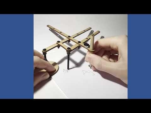
As you can see, the pantograph is perfect for enlarging text and maintaining the same proportions and style.
There are a few different approaches to using this, however, I find the easiest is as followed.
- Choose what level of scaling you're after and set up the joints as needed. Clamp the sheet of paper with what you're trying to replicate and the page you want to replicate it on between the base plates and then tighten like the videos above and below.
- Rest your non-dominant hand on the base plate. This will keep everything in place and secure for you to draw.
- Make sure the trace point can cover all of the image you're trying to replicate.
- Hold the pencil, and begin drawing by watching the movement of the trace point. At first this may feel a little strange, however, as the trace point is just doing the same movements of your hand but with smaller magnitudes it feels quite natural after a little practice. Then just go over the entire image!
Another way to use this which is more conventional for these type of mechanisms is to hold the bolt at the trace point, and move it along what you're trying to replicate. This way works as well, although only produces very feint lines that must be gone over afterwards and is sometimes harder to make sure everything lines up.
Testing & Videos
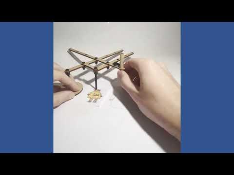
Here you can see that it can also trace out detailed images such as the Instructables logo! There are plenty more videos documenting parts of this project on my Youtube channel, I've made a playlist containing them all: Pantograph Project - AjarDesign
More Ideas
Thanks for clicking through my project and having a read - it was a cool one to learn about and construct and hopefully it's helpful to someone. This step is for a few ideas/changes I might make if I were to do it again and start from scratch.
In addition to scaling up text in diagrams for my study, I also find that it's always difficult to get this information back into compact form for use on things like formula/summary sheets that are often required - so I wanted to be able to use this tool both ways. Mechanically this is simple, we just have to swap the trace point and the image point - swapping where the tracing tool and pencil are located. However, the way I have designed the mechanism makes this much more challenging, especially whilst maintaining adjustability. This is something I plan to continue working on and release an update for eventually.