Designing Fully Parametric LEGO-compatible Pieces for 3d Printing
by GillyB2 in Workshop > 3D Printing
2925 Views, 44 Favorites, 0 Comments
Designing Fully Parametric LEGO-compatible Pieces for 3d Printing
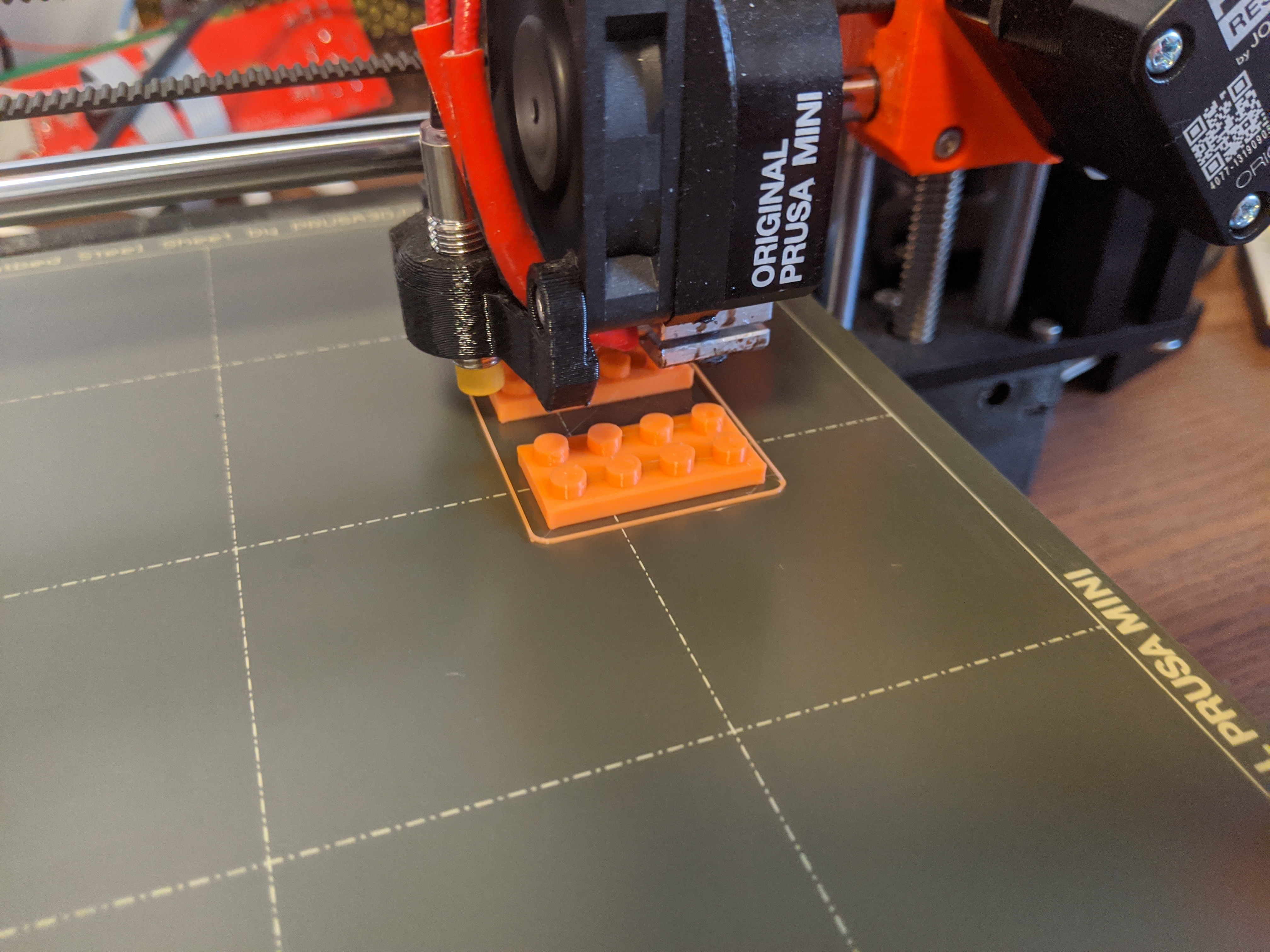
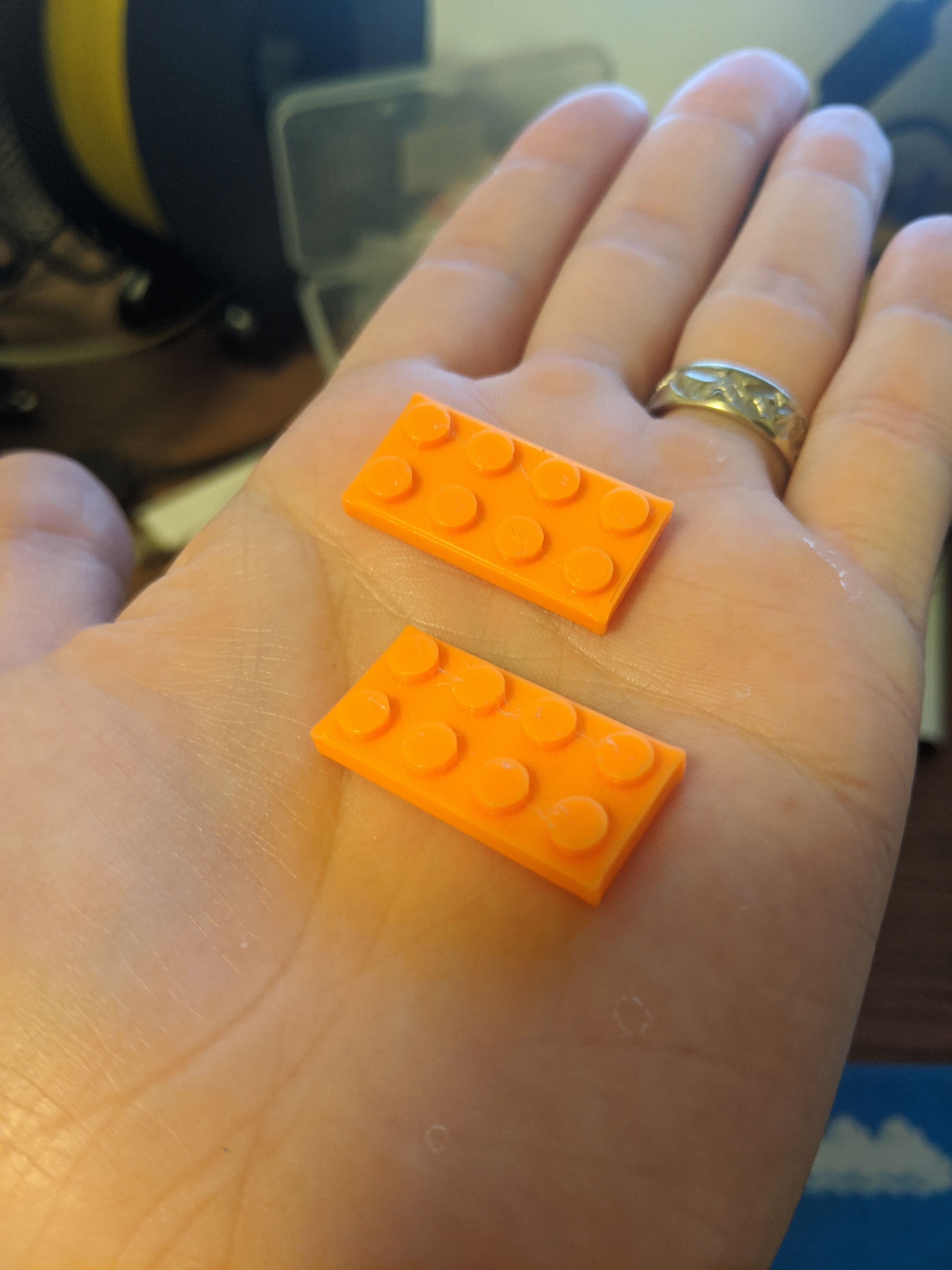
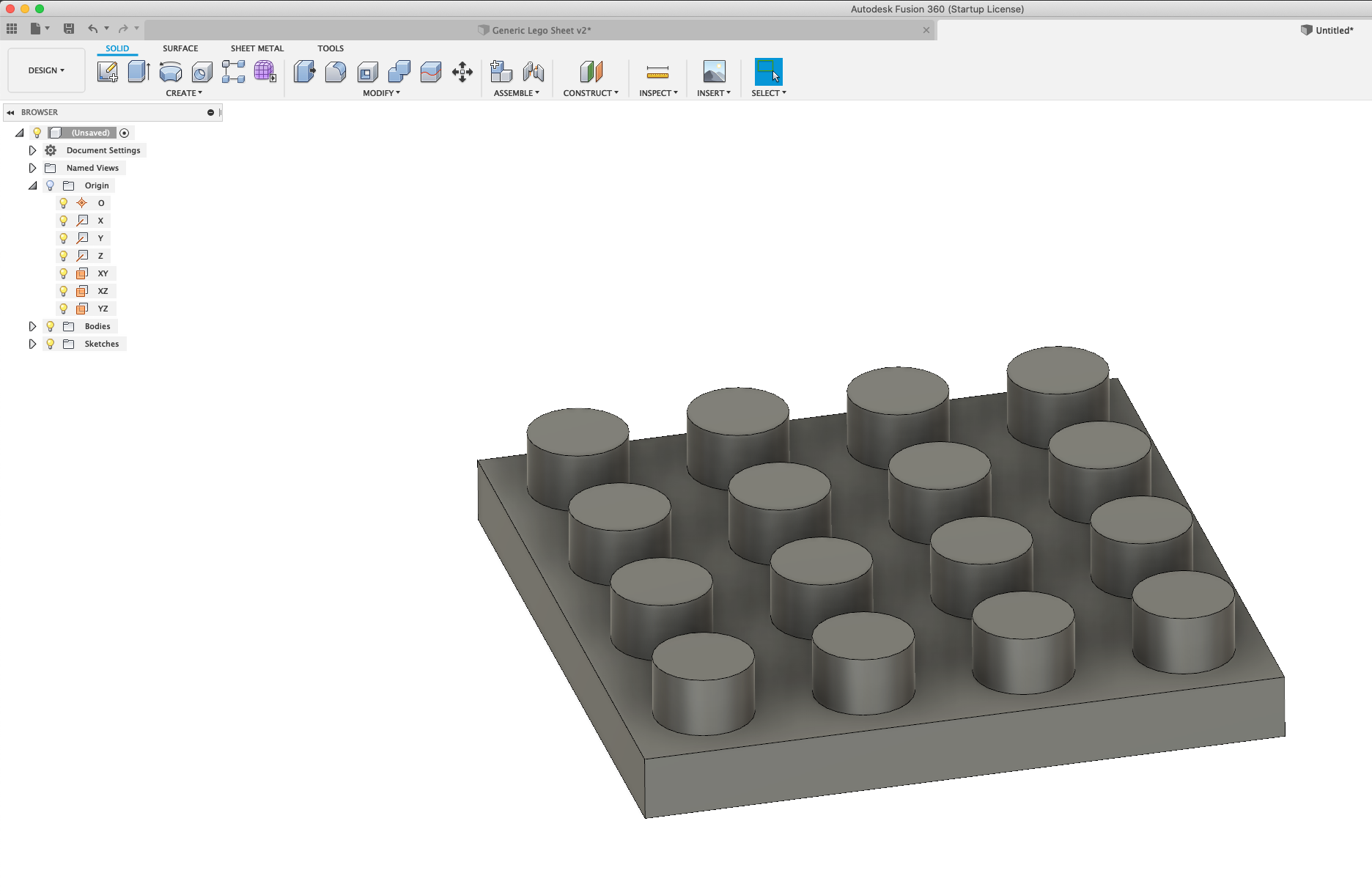
Every now and then I find myself missing a LEGO piece from one of my son's kits (or mine!) and need to print something. Since all "standard" lego pieces have the same pattern and just change in shape, I designed a LEGO piece in Fusion360 which is fully parametric, so I can modify the size and print it in any size I need.
In this guide I will show you how to build it fully parametrical. There are some advanced features here that I will explain (i.e. how to create conditional parameters in Fusion360!).
I'm assuming you have basic knowledge of creating a simple sketch and basic tools in Fusion. If you don't then there are some great videos on the official site (and you'll find a bunch on YouTube as well).
NOTE: If at any point you don't understand, or I missed something, I'm attaching the original files I created, so you can open them in fusion360 and check yourself.
Supplies
- Fusion360 installed on your computer (which is free for hobbyists/students).
- A 3d printer - I have a Prusa MINI, which is great. (If you're looking to save money and get something cheaper, I know some people that have a Creality Ender 3 and are very happy with it.)
- A digital caliper - for taking measurements. Cost ~$20 for a decent one. If you don't own one already I strongly recommend getting one!
Step 1: Examining a LEGO Piece and Taking Measurements
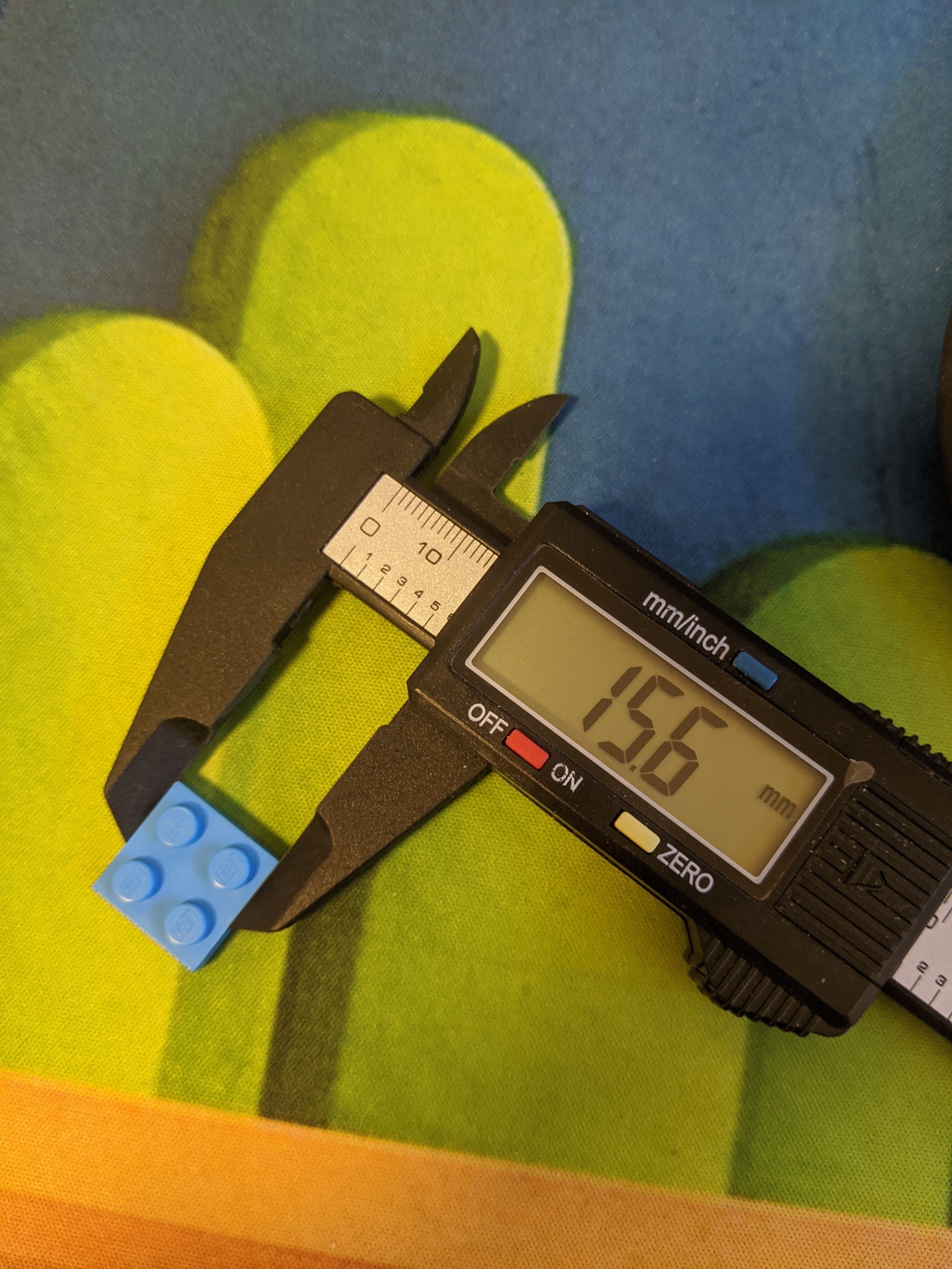
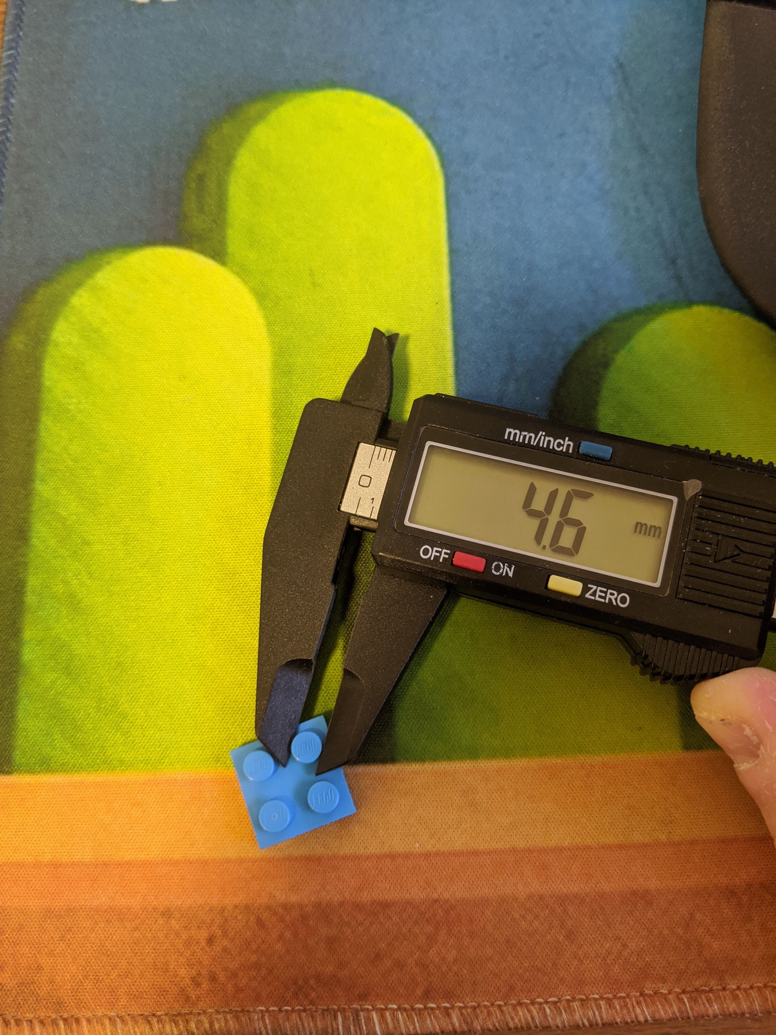
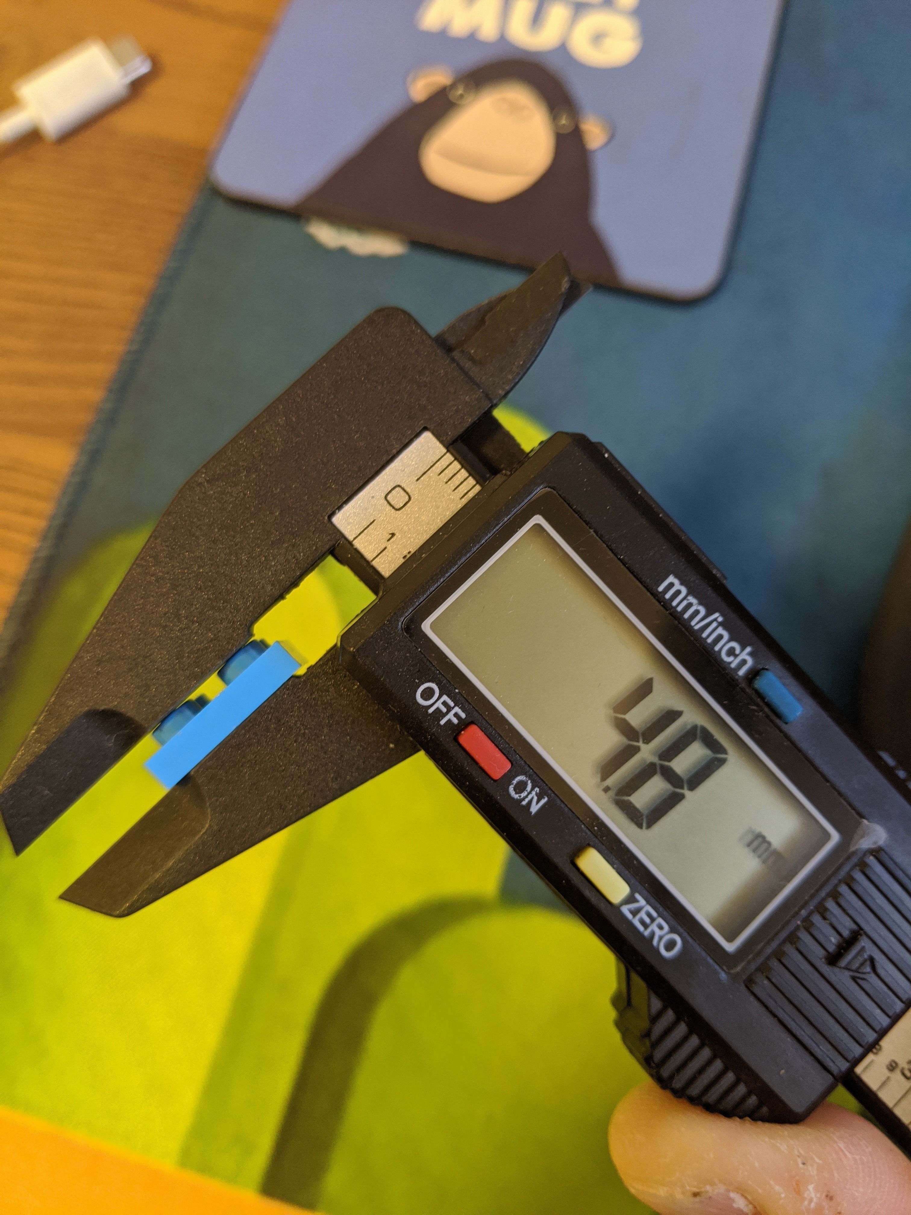
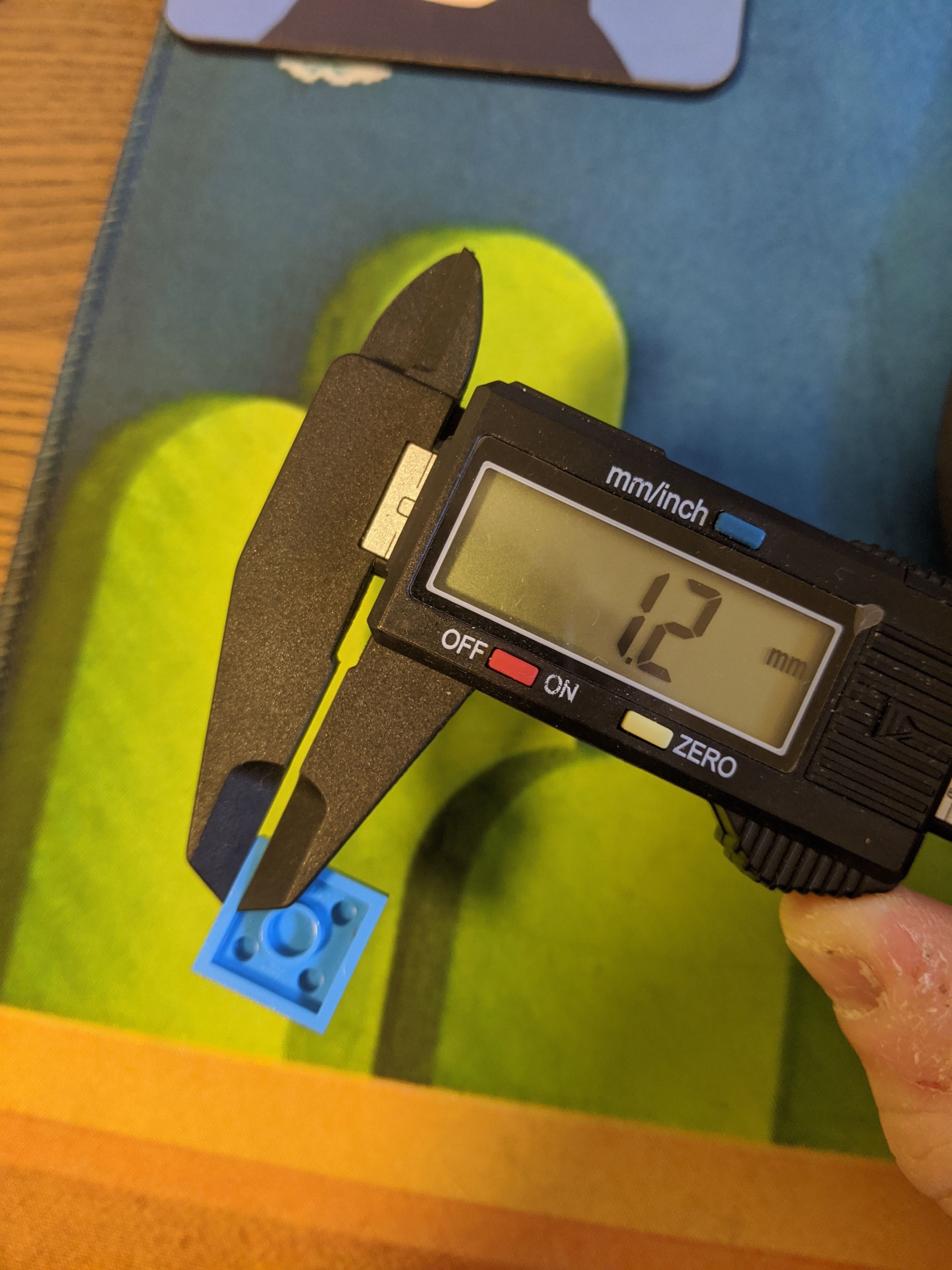
First step is to examine the LEGO piece...
Standard lego pieces are square or rectangular, and have a specific number of "studs" on them. I call the dots on the top side of it "studs" (not sure if that's the term, but I think I read that somewhere once). The pieces are usually 2x2, 2x4, 2x6, 4x4, etc. It can also be odd numbers, but they usually are sized by this increment.
I have added photos of images I found with the exact lego blocks measurements, but originally I measured all the pieces myself.
Each stud has a diameter of 4.7mm (from what I measured).
The bottom side of the LEGO pieces are made up of a border (which is the part that physically touches the floor), an inserted area (like a "roof" if looking from below), and "tubes" (which are what hold the studs of the piece they're placed on top of).
The space between the border and the tubes needs to hold the studs of the piece below it in place.
Measuring the border I got 1.2mm.
Looking at a piece that has a width of 1 stud, means its width is made of 2 borders and the diameter of a single stud. That would be (1.2 * 2) + 4.7 = 7.1mm
If I measure the width of a piece like this I get 7.6mm though - I'm assuming that's because there's an added "buffer" of space to allow the stud to actually slip in the piece above it.
For now, I'll call that the "bufferSpace" and we'll assume it's 0.1mm. We'll add it to our calculations as a parameter so we can change it later and test our prints till we get a perfect fit.
Step 2: Defining Parameters in Fusion360
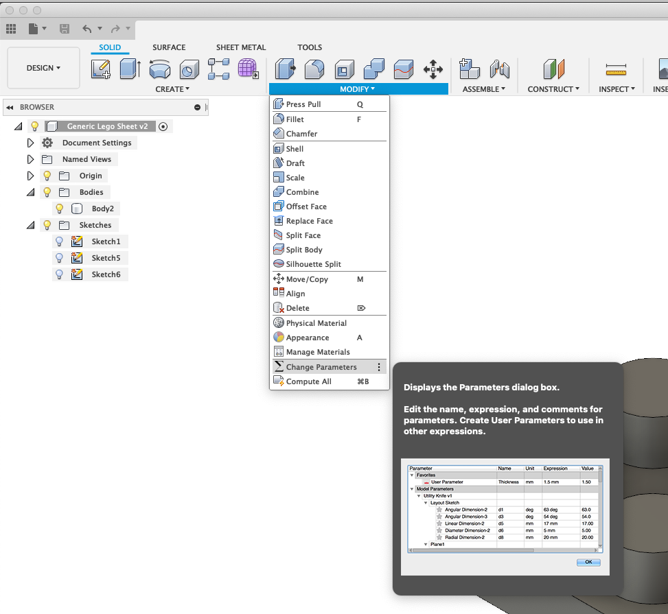
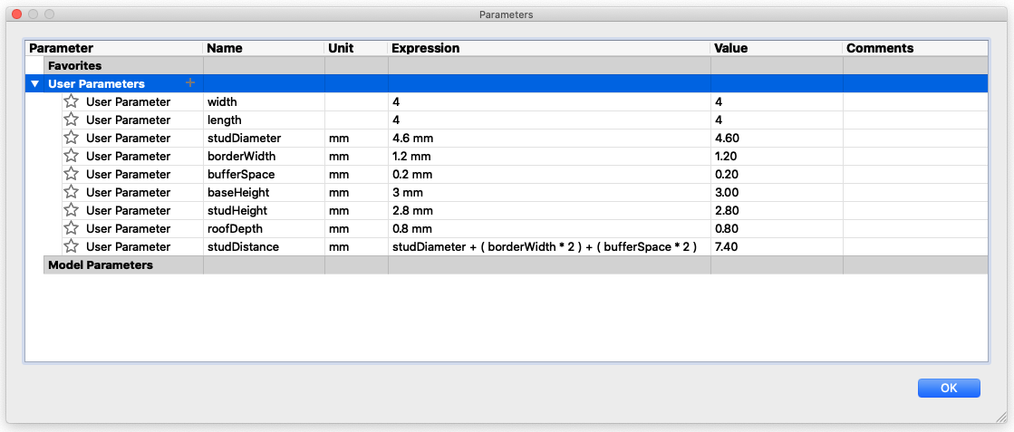
I like to start by thinking of all the parameters I'll need when designing the piece I'm working on, and defining them first so they're ready to use throughout my work.
To do that, click on the "Modify" menu, and choose "Change Parameters". A smaller window will open with a list of the parameters you defined, which if this is a new project will probably be empty at the moment.
In the row "User Parameters" you click the "+" button to add a parameter. Each parameter you need to assign a name (which you'll use a lot throughout your design), a unit and a value.
For my lego piece I'm adding the following parameters -
- width - This is a "unit-less" parameter, because it's the number of studs there is on one of the sides of the lego piece. I'll just enter '4' as the value for now.
- length - Same as "width" but the other side. (You could name these "x" & "y" - whatever's comfortable for you).
- studDiameter - This is in "mm" and I entered 4.6 for now.
- borderWidth - I measured 1.2mm
- bufferSpace - For this I'm starting with 0.2mm
- baseHeight - This is the height of the piece that's below the stud. Initially building this I did measurements on the flat lego pieces, so this had a height of 3mm.
- studHeight - 2.8mm
- roofDepth - This is the height of the base minus the height of the inset on the bottom. (If you imaging the inner space of the lego piece a house, then this means the measurement from the ceiling to the roof).
- studDistance - This is the distance from the center of a stud to the center of the stud next to it. This can be calculated using the other parameters we defined till now, and we can reference them by their name in the value. The distance between studs is: (studDiameter + (borderWidth * 2) + (bufferSpace * 2))
I know that placing two pieces with 1 stud next to each other take up the same space as 2 studs, which means that in between the studs there's a distance of 2*borderWidth. I'm adding twice "bufferSpace" cause i'm imagining that as a buffer on each side of each stud.
Great! Now we're ready to start sketching our piece.
Step 3: Creating the Base
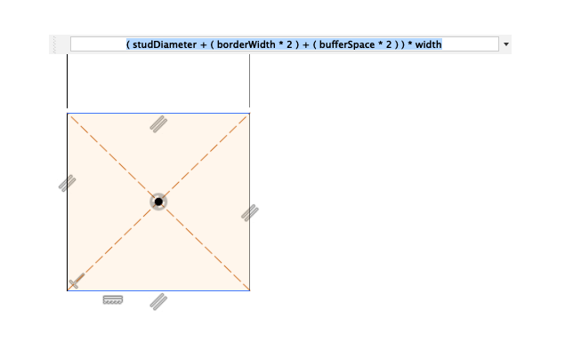
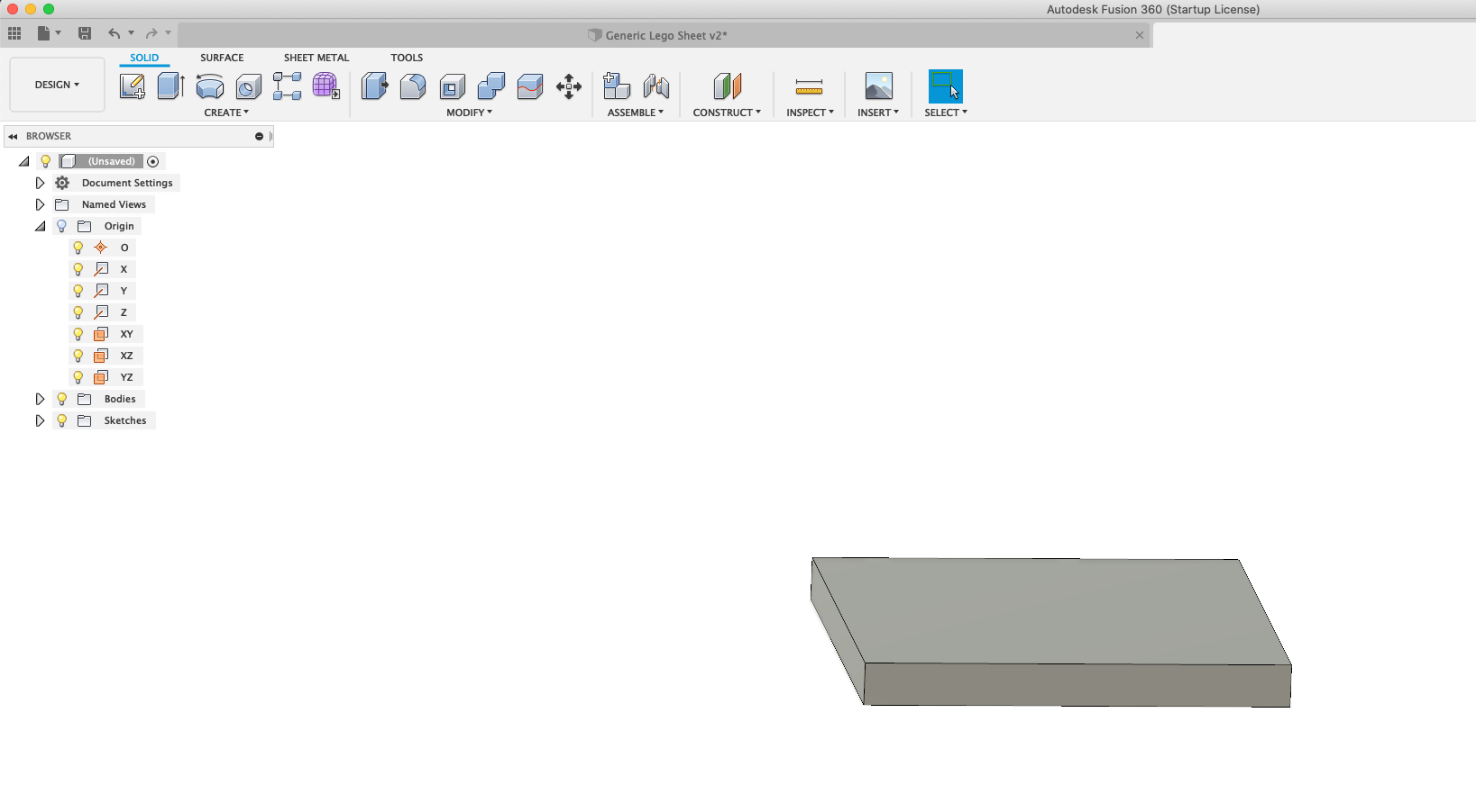
To create the base, we'll start by just sketching a square.
Click "Create Sketch", choose a plane to sketch on and choose the "rectangle" shape and just draw a rectangle.
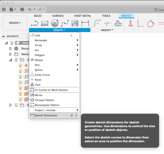
At first it doesn't matter the size, I just quickly create a rectangle. In the "sketch" menu, you choose "sketch dimension" (I do this by just hitting "D" on the keyboard) and now you can define dimensions for the square/rectangle you created.
Click on one of the sides and you'll get an input to enter the size. Here we will define the size only using our previously defined parameters.
First side will be:
(studDiameter + (borderWidth*2) + (bufferSpace*2)) * width
The other side will be exactly the same except for multiplying by 'length' instead of 'width'.
Hit "Finish Sketch" in the menu.
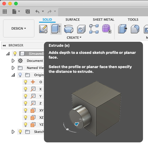
Now, let's extrude the piece, using the "extrude" button on the "solid" menu above.
You can also use the shortcut "e" for this.
We're going to extrude this by "baseHeight" (using our parameter).
Now you should have a block.
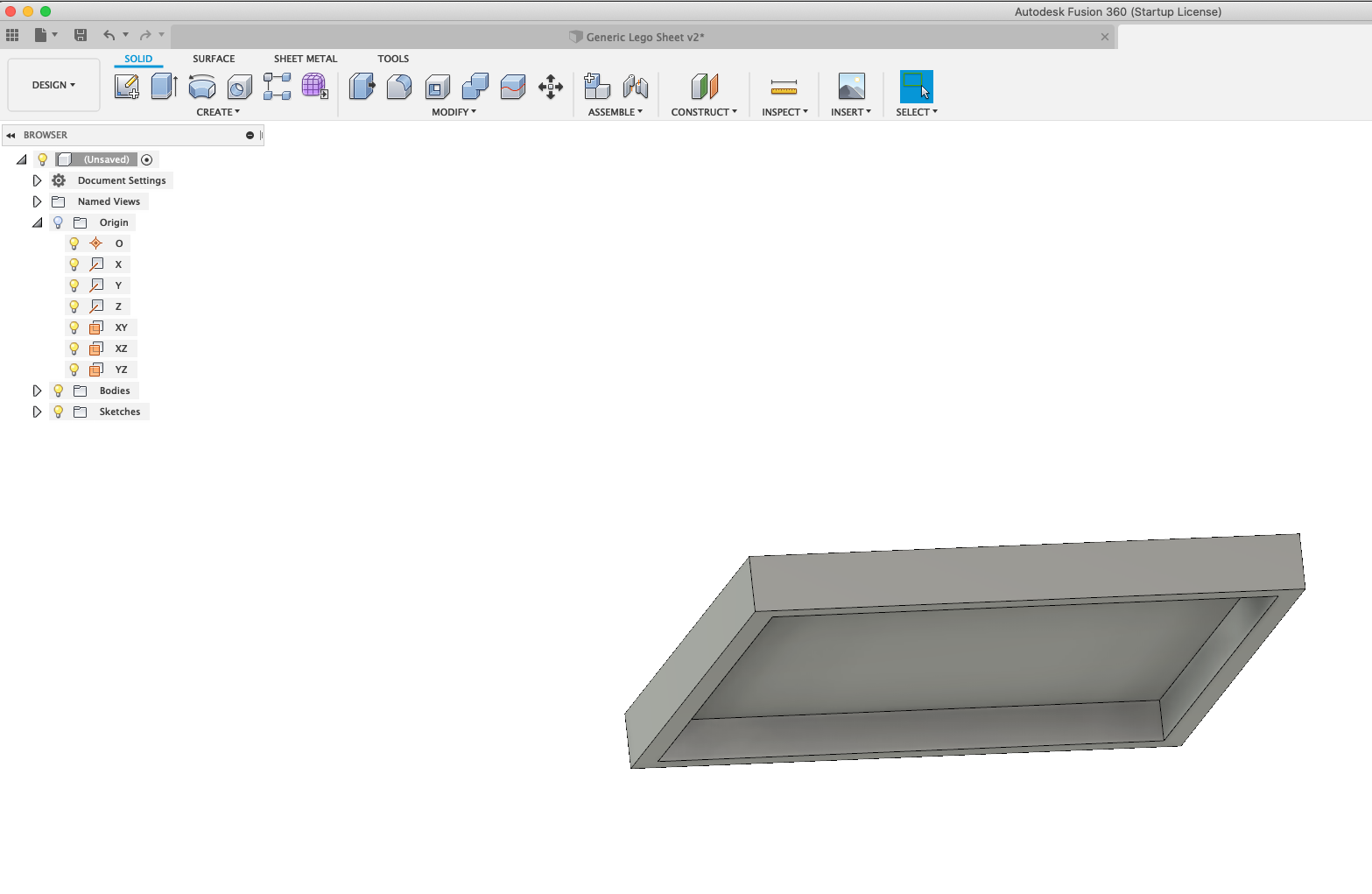
Now we're going to create an 'inset' on the bottom -
Rotate your block, select the bottom face, and right click and select "create sketch".
Draw a rectangle on the bottom that's smaller than the rectangle face we're drawing on, and add some dimension constraints - Using the dimension tool, we're going to define the distance between the new rectangle and the border. The distance here should be the size "borderWidth" on all sides.
Finish this sketch, select the new rectangle you just drew, and extrude again. This time we'll be extruding the inset, which should be
-(baseHeight - roofDepth)
Now we're done with the base of the block. All parametric!
You can already see the nice thing of parametric design if you open the "parameters" window and change the "width" or "length" to a different number, and you'll see the size of the base changes automatically!
Step 4: Creating the Studs
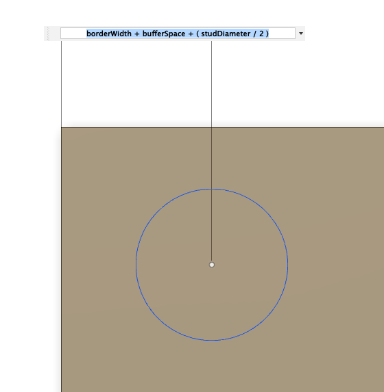
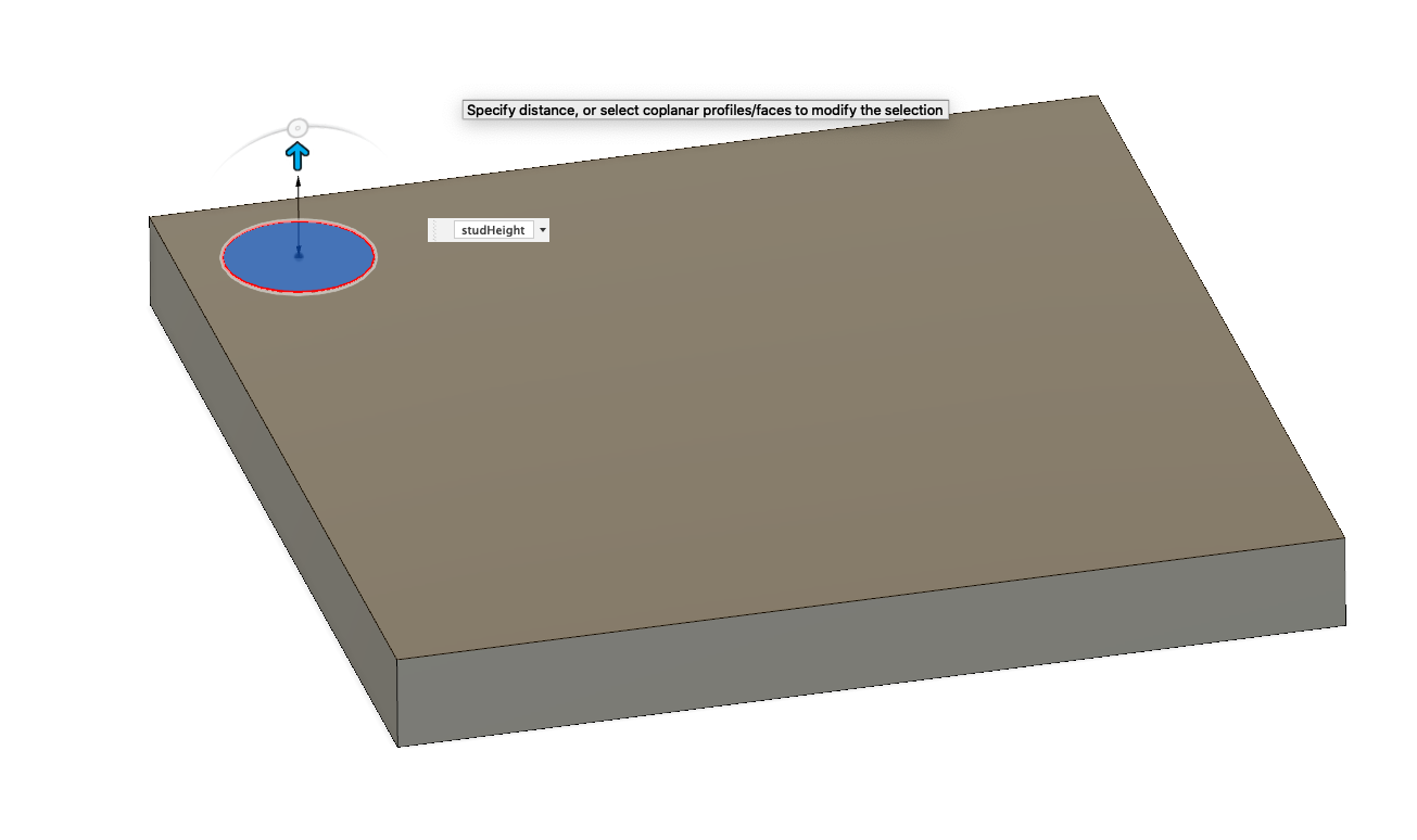
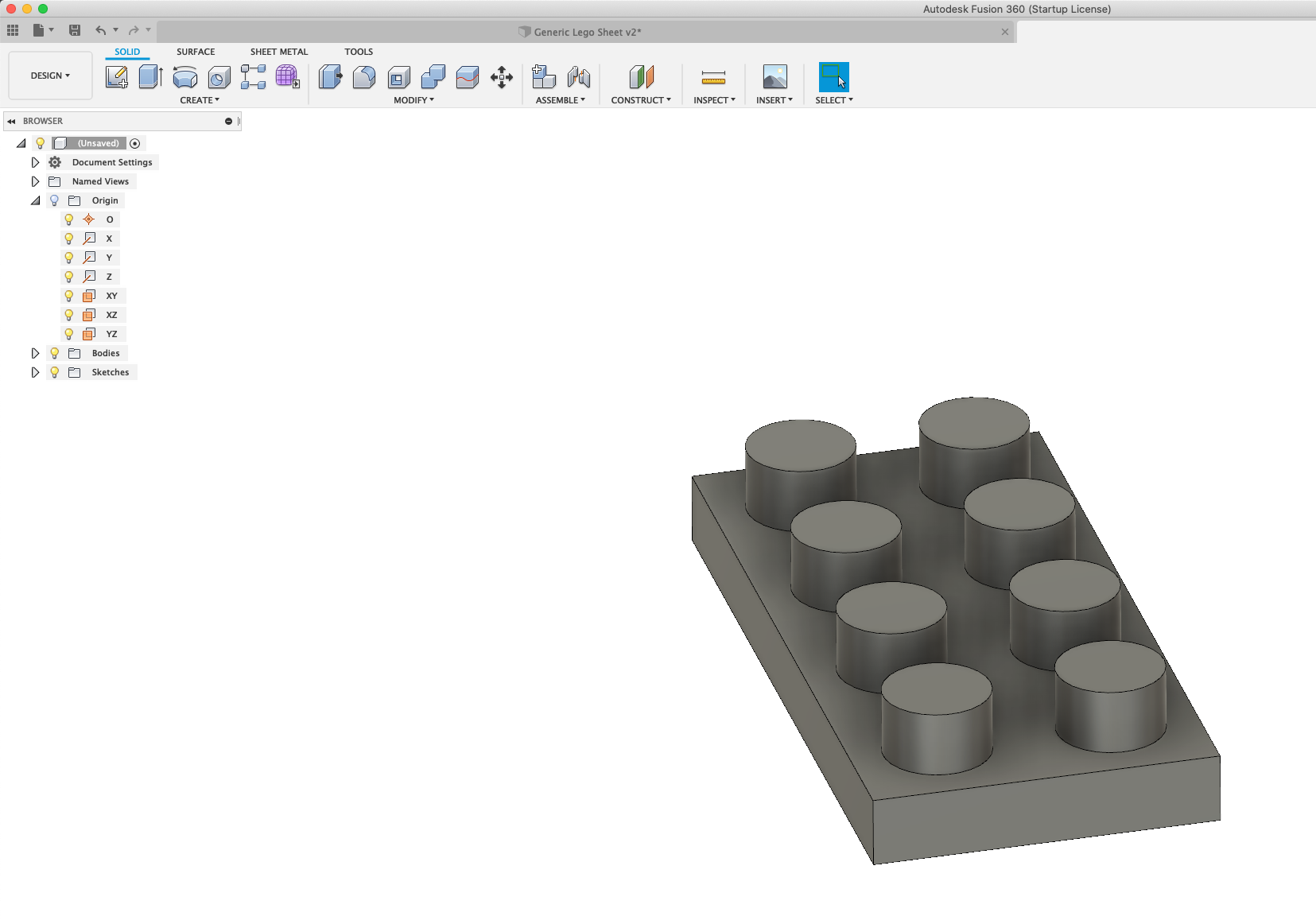
Click on the top face of the lego piece. "Create Sketch" and draw a circle next to one of the corners (position isn't critical at first).
We're going to add dimension constraints here - It's easiest to constraint the distance of the center of the circle to the sides of the rectangle. In this case the distance from each side will be:
borderWidth + bufferSpace + (studDiameter / 2)
The diameter of the circle we'll also constrain to "studDiameter".
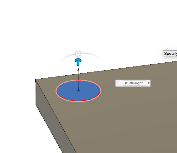
Rotate the block, hit "finish sketch", select the circle we just drew, and we're going to "extrude" it again. This time the size of the extrusion will be "studHeight".
Now for some magic!
Instead of creating each stud individually, we're going to define a "pattern"..
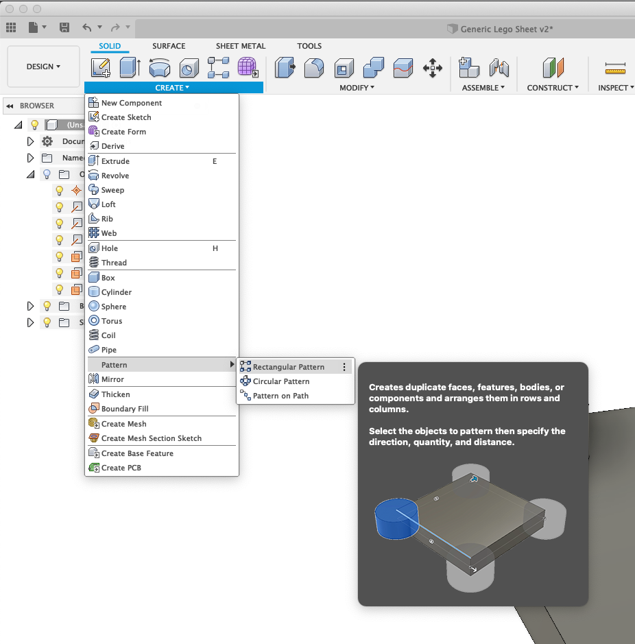
Click "Create" (under "Solid"), then "pattern", and then "Rectangle pattern".
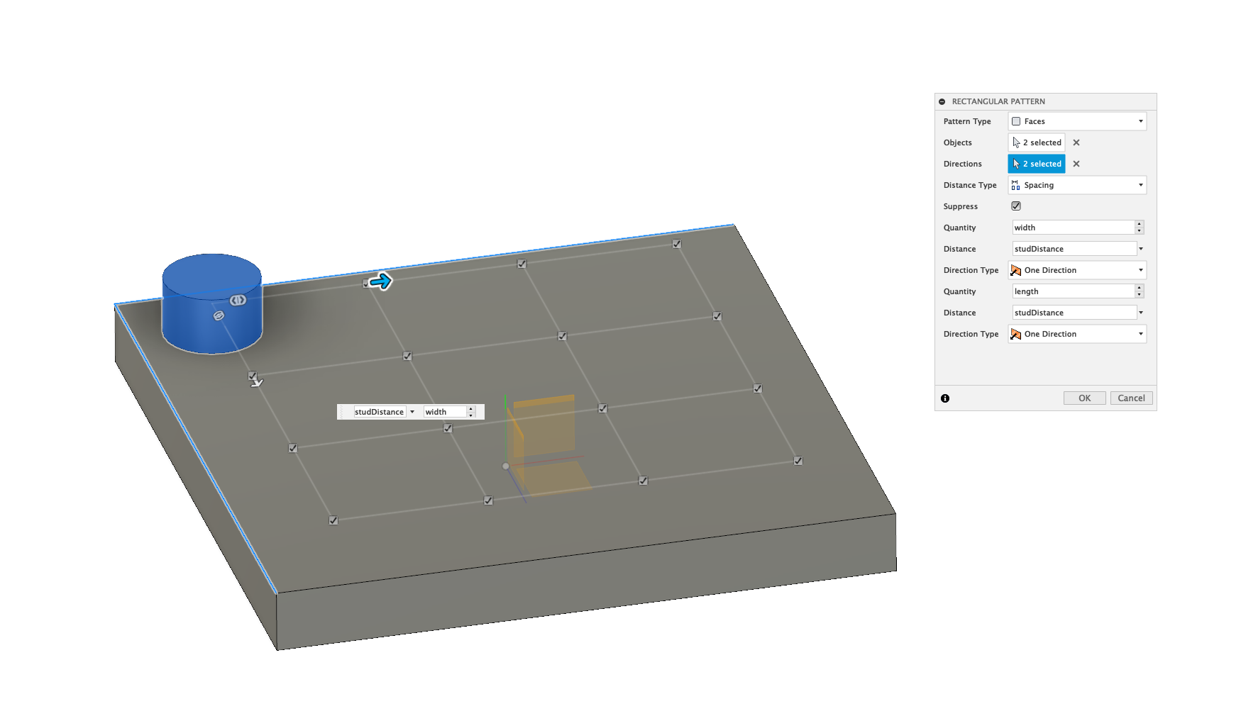
Then you'll need to select the faces of the stud - that means the top of the stud, and the cylinder itself.
In the small window that opened, you'll need to choose how many you want to repeat for each direction, and the distances between them.
For the amounts you enter on one "width" and the other "length".
For the distances between them just type "studDistance".
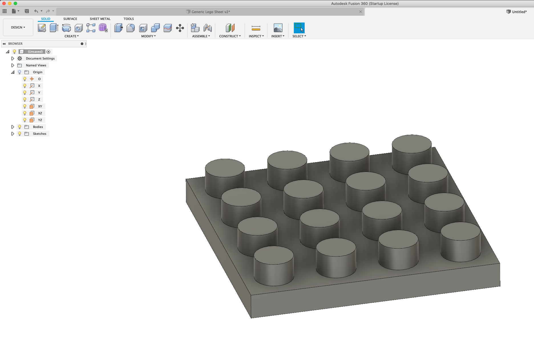
You should see the studs multiplied on the whole base if done correctly, after hitting "ok".
You can look at the images I added to see how to fill in the parameters properly.
Again, you can test our progress by opening the "parameters" window, change the width or length and make sure our block changes accordingly. (If you mixed up "width" and "height" in the pattern window, you'll realise that now, so just edit the pattern by right clicking on the "pattern" icon in the bottom part of the window on the timeline and choose "edit feature" - the pattern window will open again, and you can change the parameters of the pattern).
Step 5: Creating the Tubes
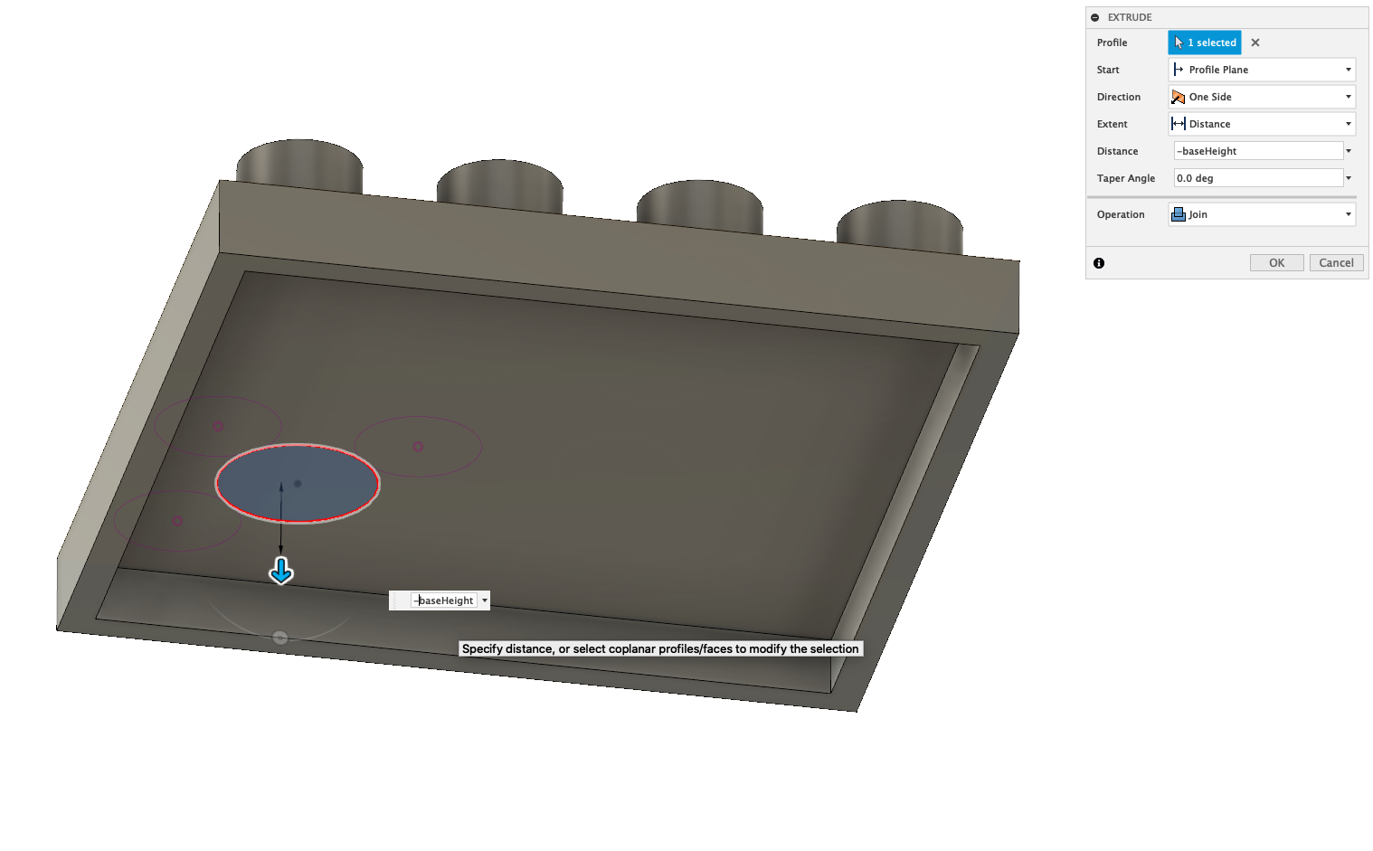

Right click on the top of the base again, and create another sketch. I'm doing this on the top of the base and not the bottom, because I want to use the help of the sketches of the studs for this as well.
Draw a circle approximately where the tube is supposed to be and just randomly size it. Then we're going to add a "tangent" constraint. Select "tangent" from the "constraints" menu at the top of the window (look at the images I added for reference).
We're going to click on the diameter of the circle, and then select the circles around it. We should do this to 3 circles, which is enough to 'fully constraint' the tube.
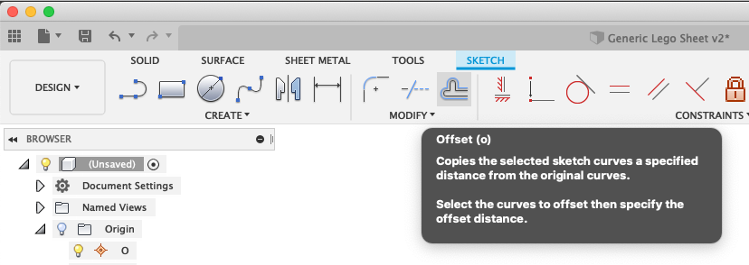
We don't want the tubes to be exactly at this size, since we want to leave that tiny buffer. So in the sketch menu we can choose 'Offset', and then select the circle we created. For the amount, enter "-bufferSpace".
Hit "finish sketch", select the new circle we drew (the smaller one), and hit "extrude". We're going to extrude this by "-baseHeight". Make sure in the "extrude" window you select "join" for operation (and not "cut").
Now, we have the first tube ready. Similar to the studs, here too we're going to use the 'pattern' tool to clone this in the exact shape of our lego piece.
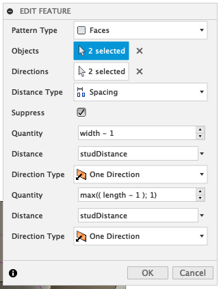
Select the "rectangle pattern" tool again, select the first tube we created and the directions. This time, for the amount of copies we'll need to enter "width - 1" and "length - 1" because there's 1 less tube in each direction than the amount of studs. For distance we'll enter "studDistance".
That's it! We now have a parametric LEGO piece!
You can go to the 'parameters' tool window, just change the 'length' or 'width' parameter to create any LEGO size block you want. You can also play with the 'baseHeight' and other parameters to create different variations as well.
Step 6: Advanced Parameters!
You might have realised that our LEGO pieces can fit any number of studs in any direction as long as there's at least 2 in each direction. In lego pieces that are 1x4 studs for example, the size of the tubes on the bottom of the piece are much smaller (since they don't need to fit in between 4 studs when connecting on another piece, but only between 2 studs).
So, in order to make our LEGO piece generic enough to handle this case as well, we'll need to make two major changes to our design:
- Change the size of the tubes to be parametric - meaning dependant on the other parameters we defined already.
- Add a condition to the 'tubeSize' parameter that we'll add, so that if there's only a single row of studs it will be a certain value, and if it's 2 or more, then it will give us another value.
The first step:
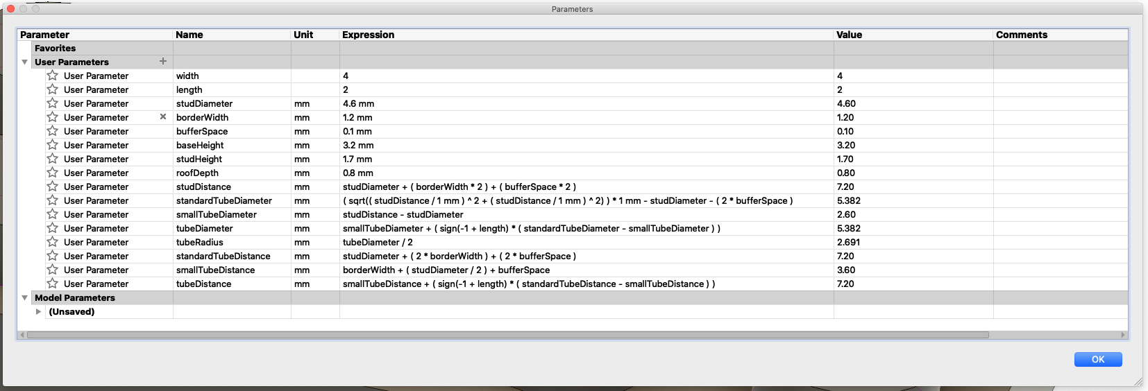
We actually need to create two new parameters - 1 will hold the tube diameter when there's two or more studs in each row, and the second parameter will have the tube diameter when there's 1 stud in one of the rows. We'll call these parameters "standardTubeDiameter" and "smallTubeDiameter" respectively.
Let's go to the parameters window, and create the first parameter (standardTubeDiameter), and for the expression we'll do some arithmetic calculations (based on the Pythagoras theorem) to reach the value of:
(sqrt((studDistance / 1 mm) ^ 2 + (studDistance / 1 mm) ^ 2)) * 1 mm - studDiameter - (2 * bufferSpace)
Now create another parameter, called "smallTubeDiameter", and for the expression we'll enter the value:
studDistance - studDiameter - (2 * bufferSpace)
Ok, we have two parameters - one for each tube size. Now we need to create two different parameters for the distance of the tube from the edge, since when there's only a single row of studs then the tube is also closer to the edge.
Create another set of parameters called "standardTubeDistance" and "smallTubeDistance" and for their expressions enter:
standardTubeDistance = studDiameter + (2*borderWidth) + (2*bufferSpace)
smallTubeDistance = borderWidth + (studDiameter/2) + bufferSpace
Go back to the original sketch, edit it, remove the 'tangent' constraints we added, and edit it so the distance from both edges will be "standardTubeDistance". (In the next paragraph i'll explain about creating conditions in the parameter expression, so we'll change one of these distances).
Now we'll need to add our condition so that it will be dynamic depending on the length and width of the lego piece we want to create. This is the interesting part (in my opinion!) !!
Second step:
Fusion360 doesn't really have a syntax for creating a condition inside a parameter expression, but with some clever math tricks we can get around this limitation :)
There is a method called 'sign()' which given an expression, returns '0' if the result is less or equal to '0', and it will return '1' when the expression is greater than zero. If we multiply this by a certain number, then in the case of zero we'll get zero, and in the case of '1' we'll get the number we multiplied by.
Using this trick allows us to create a 'condition' that we can use for our parameters. I'll give a simple example of how to use this trick before using it with our parameters to make sure that it's clear.
Let's say I want a parameter to return '2' if "length" is 1 and for any "length" greater than 1 I want our parameter to return '6'.
In pseudo code this will look like this: If (length == 1) return 2; else return 6;
(I'm assuming here that 'length' can't be negative).
Using the trick I explained above, we can write the expression in fusion like so:
2 + (sign(-1 + length) * 4)
Try different values here for 'length' and see what you get!
So, in our case, we'll create another parameter that will return "smallTubeDiameter" if "length" is 1 and will return "standardTubeDiameter" if "length" is greater than 1.
Our expression will look like this:
smallTubeDiameter + (sign(-1 + length) * (standardTubeDiameter - smallTubeDiameter))
To define the dynamic tube distance from the edge, we'll use the same trick. So create another parameter called "tubeDistance" and we want this expression to return "smallTubeDistance" when "length" is 1, and to return "standardTubeDistance" when "length" is greater than 1.
It will look like this:
smallTubeDistance + ( sign(-1 + length) * (standardTubeDistance - smallTubeDistance) )
Now you just need to fix the distance of the tube from the edge in the sketch so the distance from one edge is "standardTubeDistance" and the distance from the other edge is "tubeDistance" (which is our dynamic value).
Once you're done with all these new parameters, it's time to test it by changing the length of the lego piece in the parameters window. If you change it to '1' you should see it work out.
While I was testing this myself, I ran into a small bug in my design... Fusion360 told me there was an error with the 'pattern' feature I created for the tubes, so I opened the window to edit the parameters. Turns out that when 'length' is '1', then the quantity is '0' which is an invalid value. To overcome this I used the 'max' function, so I changed the Quantity value to be:
max(length - 1; 1)
This means if 'length - 1' is zero, then it will return '1' and if not, it will return 'length - 1'
Step 7: Printing the Parts
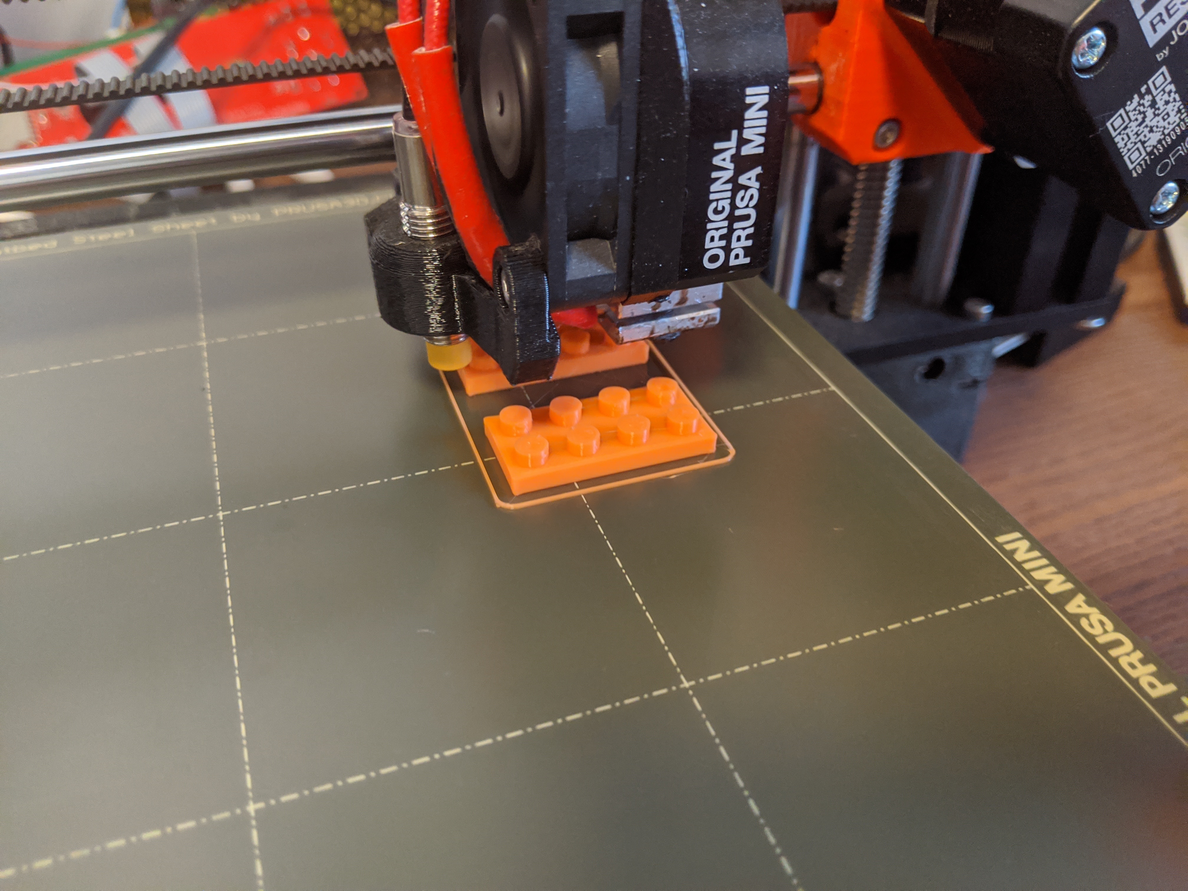
Finally we're ready to print and test out our design!
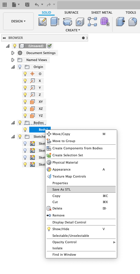
To export from fusion you just select the body in the browser tree on the left, right click on it and select "export to STL".
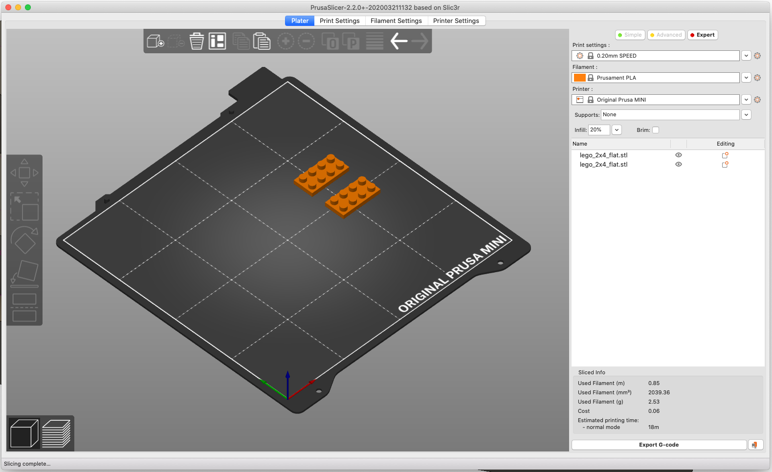
I then slice it with the PrusaSlicer.
I have a Prusa MINI, so I just choose the slicing profile for PLA, and choose "Quality 0.2mm" with 20% infill, place the lego pieces on the heatbed in the slicer and hit "Slice Now".
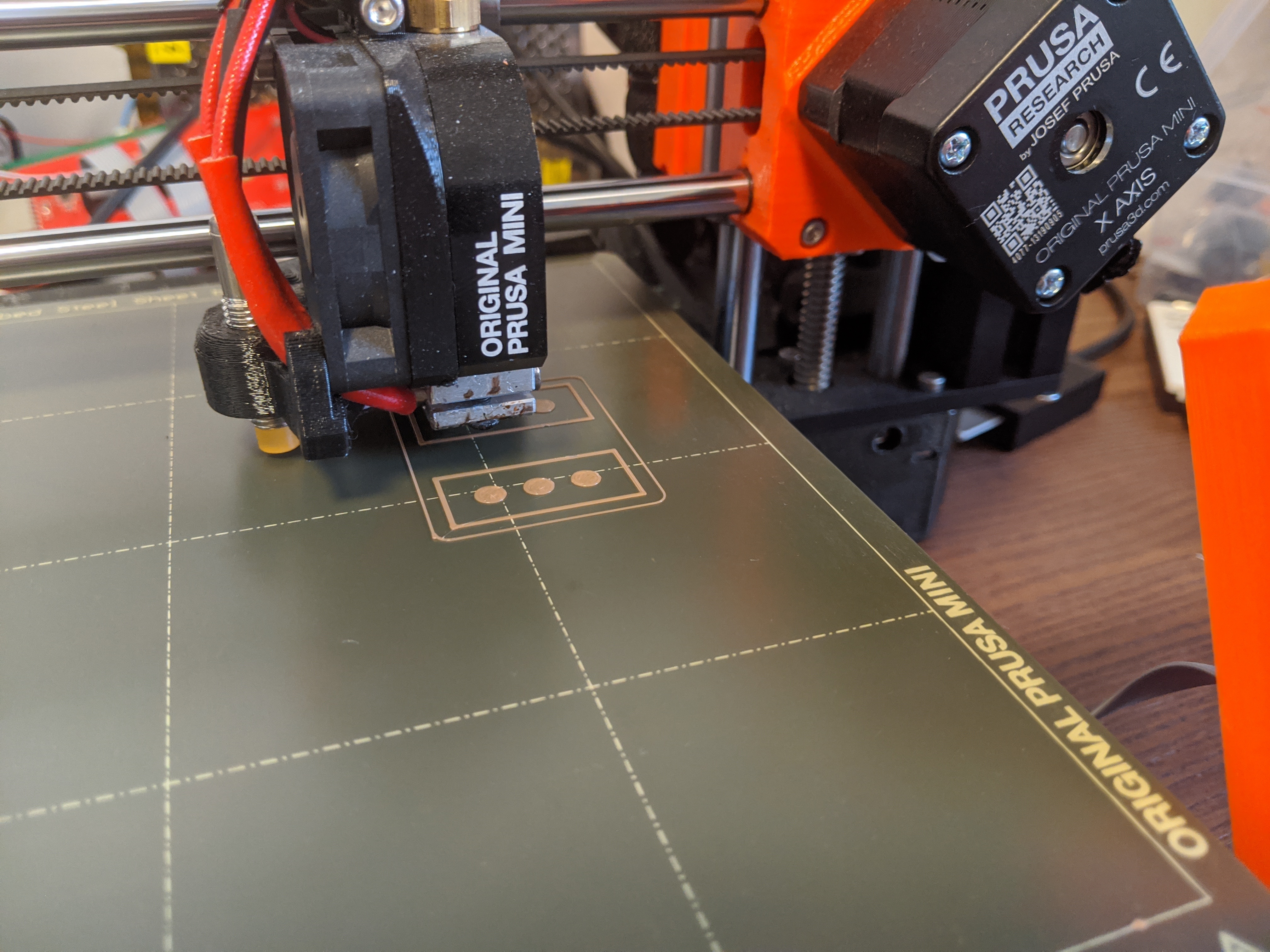
I'm literally printing this for the first time while typing this instructable!
Turns out the lego pieces don't fit together that well and seem to have too much 'moving space' between them. I tweaked the size a little, especially the "bufferSpace" and reprinted.
After reprinting with bufferSpace=0.1mm it still had too much moving space in my opinion, so I made it 0 and then it came out good in my opinion.
You might need to tweak this a bit, it really depends on the resolution and quality of your 3dprinter.