Design for Mini Airplane
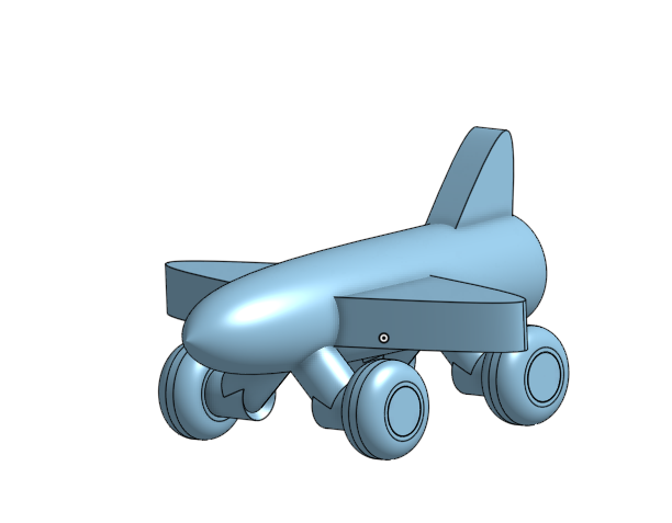
The airplane is one of the biggest and unique inventions made by man. The average airplane is around 200 feet in length and 150 feet in width. With this project I took an airplane and scaled it town to a size that would fit in the palm of your hand. This airplane will be 4 inches in length and 3 inches in width. I decided to enter in the 'Big and Small' contest to make a unique invention and turn it into something that is very small.
Supplies
- OnShape on Computer - for the designing process
- 3D Printer - So you can actually make it
Body of Plane
.png)
.png)
.png)
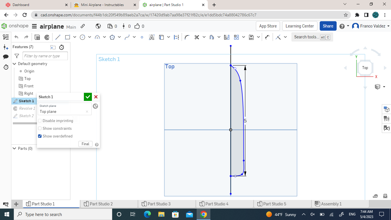
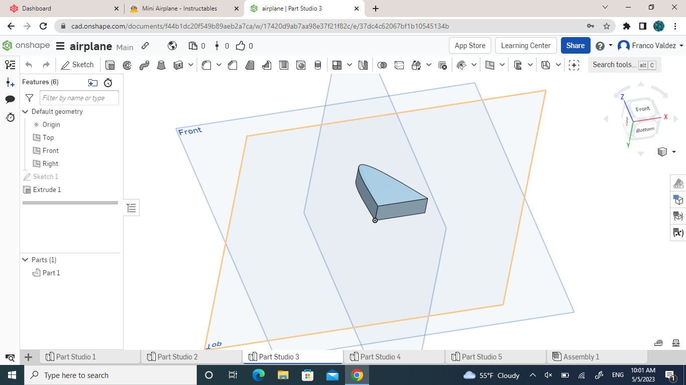
- First, you will make a sketch on the top plain
- On that sketch you will make a line 4 inch line vertically since we are making a plane small
- You will use the spline tool to create the shape of your plane
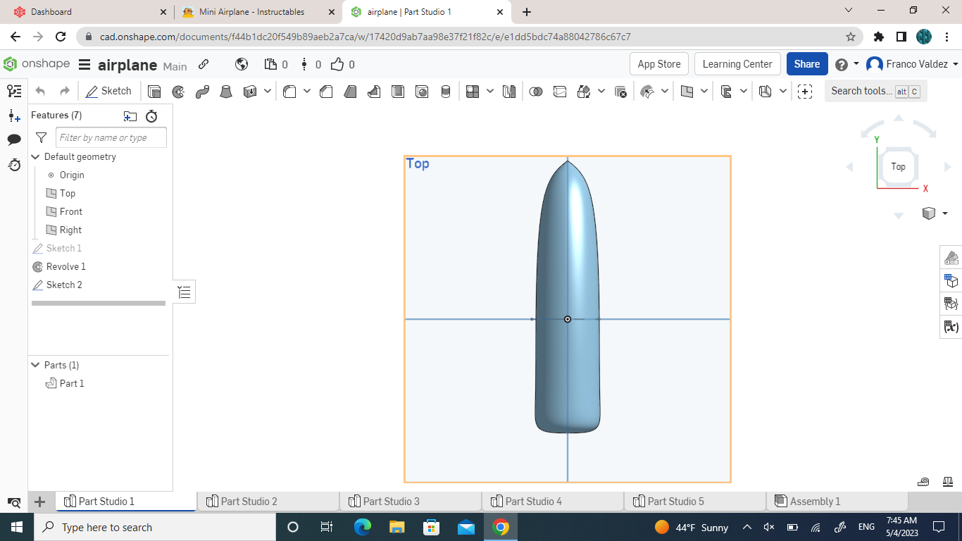
- After you're done with that sketch, you will revolve the shape you created to make it into 3D
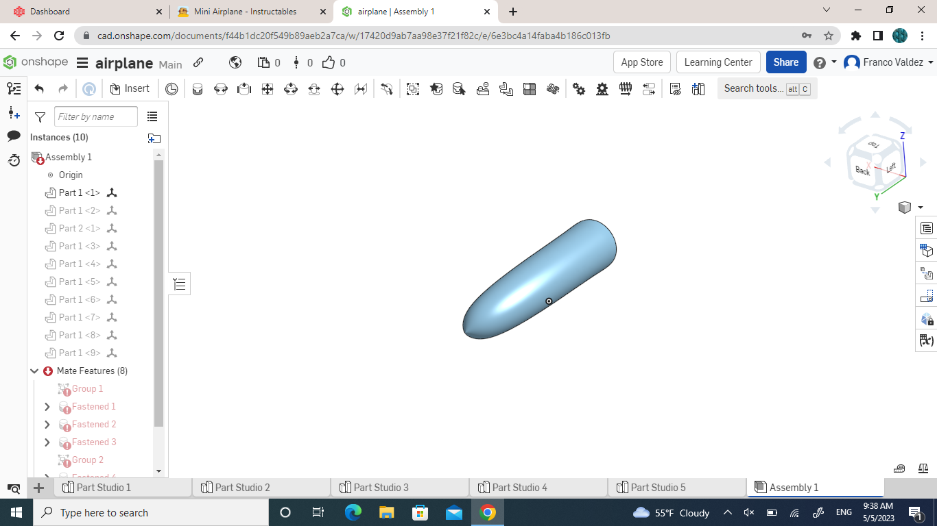
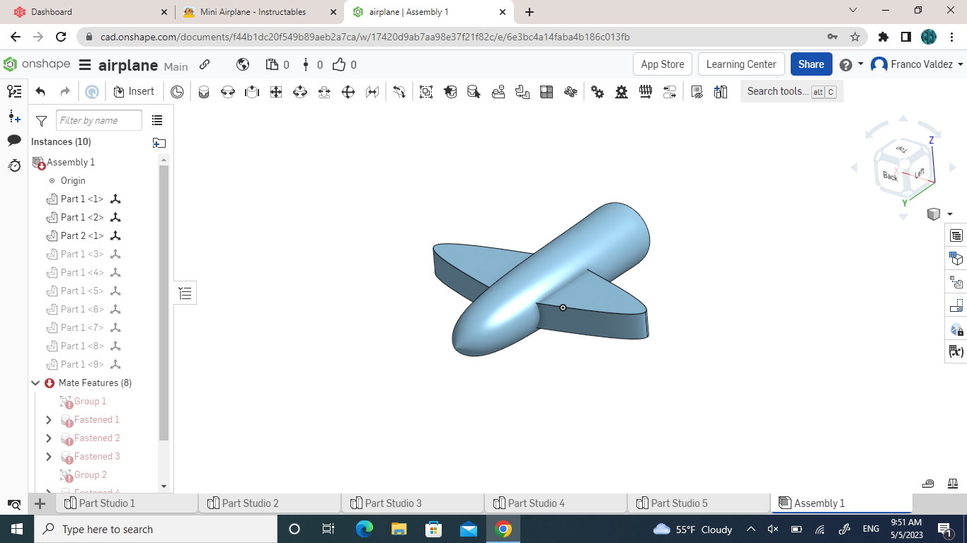
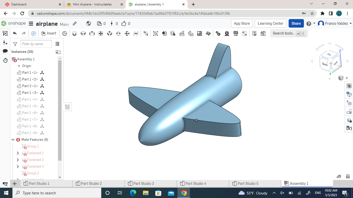
- You will then insert it into the assembly page
Wings
.png)
.png)
.png)
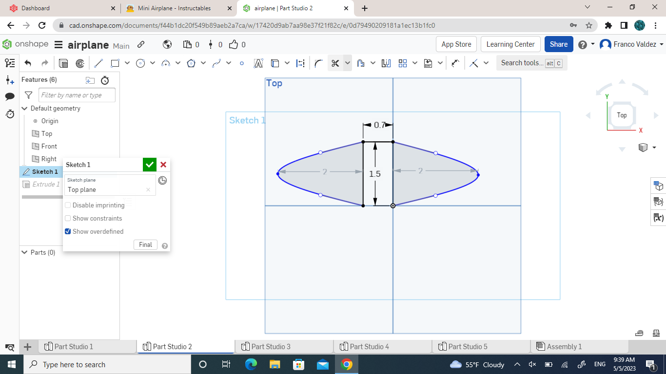
- For the first step of this part you will create a new part studio and create sketch on the top plain, and you will create a line that is 1.5 inch vertically
- Then, with the spline tool you will start from the top of the 1.5 inch line and go out 2 inches and connect it to the bottom of the 1.5 inch line
- And you will space out the other wing .7 inch from the first wing and will follow the exact same steps as you did to make the first wing.
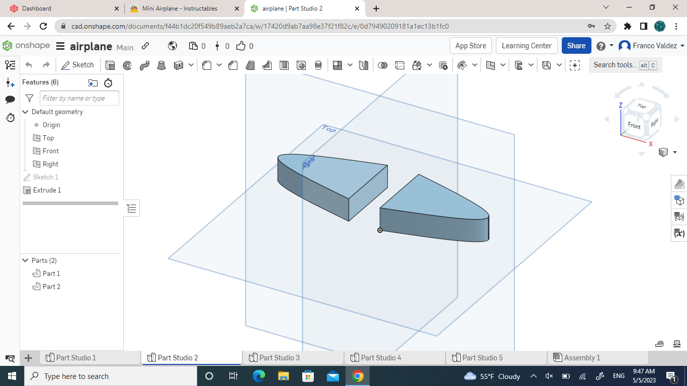
- After you are done with that sketch, you will then use the extrude tool and extrude both of the wings 0.5 inch
- And you will insert those in the assembly page and connect them with the body of the plane
Tail
.png)
.png)
.png)
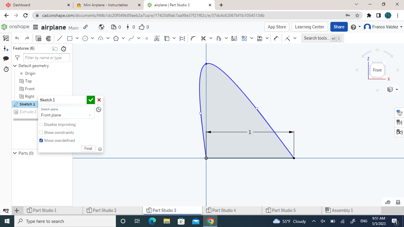
- On this step you will create a new part studio and create a sketch on the front plain and make a 1 inch line horizontally
- Then, using the spline tool you will start at one end of the line, and make any design of a plane tail and connect it to the other end of the line
- When you finish the sketch, you will extrude the tail 0.5 inches.
- You will then insert it into the assembly page and connect it to the end of the body of the plane
Wheel Holders
.png)
.png)
.png)
.png)
.png)
.png)
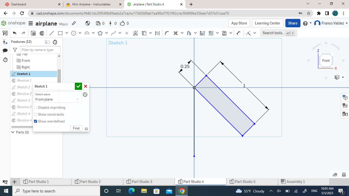
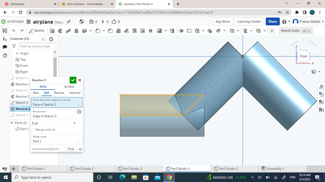
- For this you will create a new part studio and make a sketch on the front plain. Starting from the middle, you will make a line 1 inch long that is 45 degrees from the horizontal line and from the middle you will make a 0.25 inch line that will go up 45 degrees from the middle. connect those two lines to create a rectangle and you have yourself your first tube like object
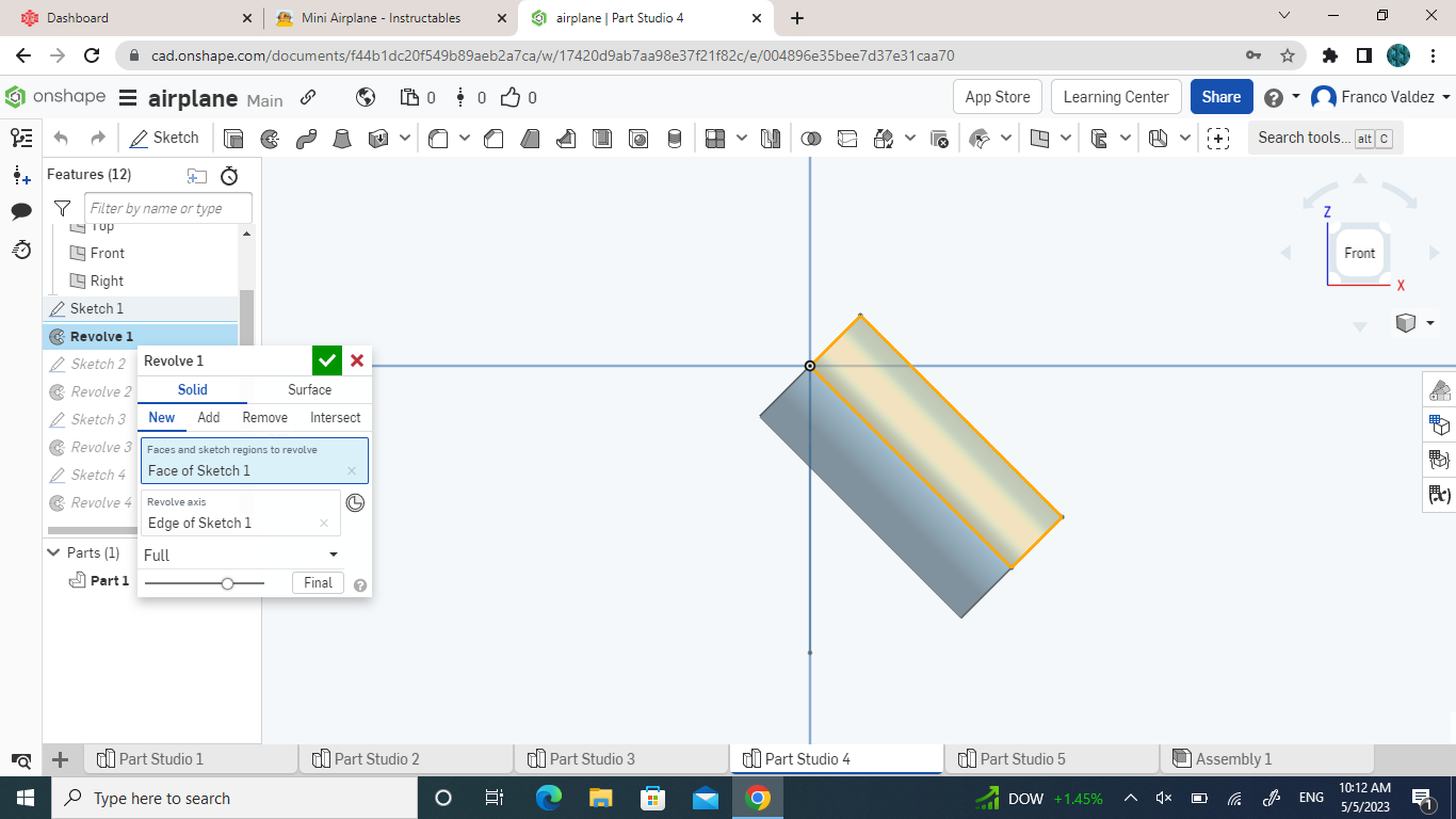
- You will go ahead and revolve this shape around the axis of the bottom line that you created
- On a different sketch on the same plain, you will repeat all of those steps to get the same shape on the other side
- On a different sketch on the same plain, you will make a line from the middle at the bottom of the tube like object and make it 0.75 inches long, you will go 0.25 inches up and connect it inside the object.
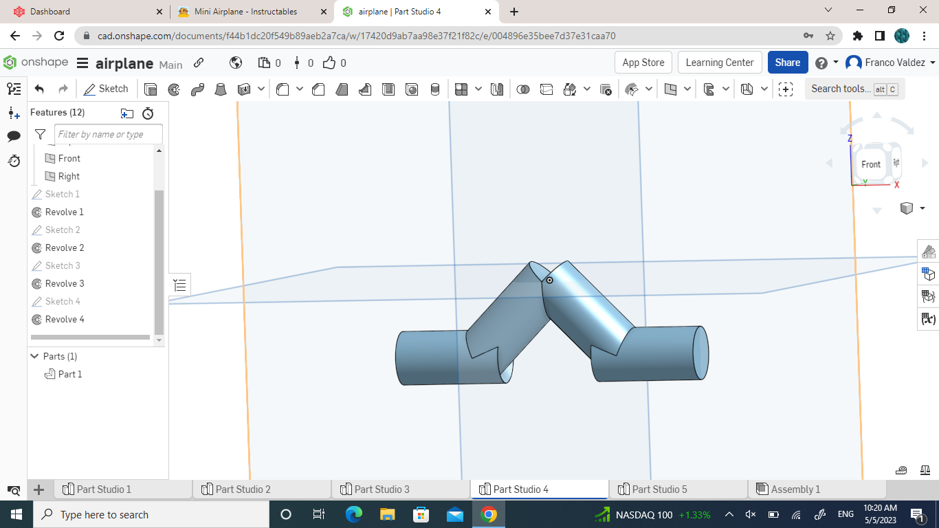
- Revolve that object around the bottom horizontal line you made.
- Repeat the last 2 bullet points on the opposite side
- You then insert this object twice into the assembly page to have one in the front and one in the back
- Connect these two to the bottom to have set in the front and a set in the back
Wheels
.png)
.png)
.png)
.png)
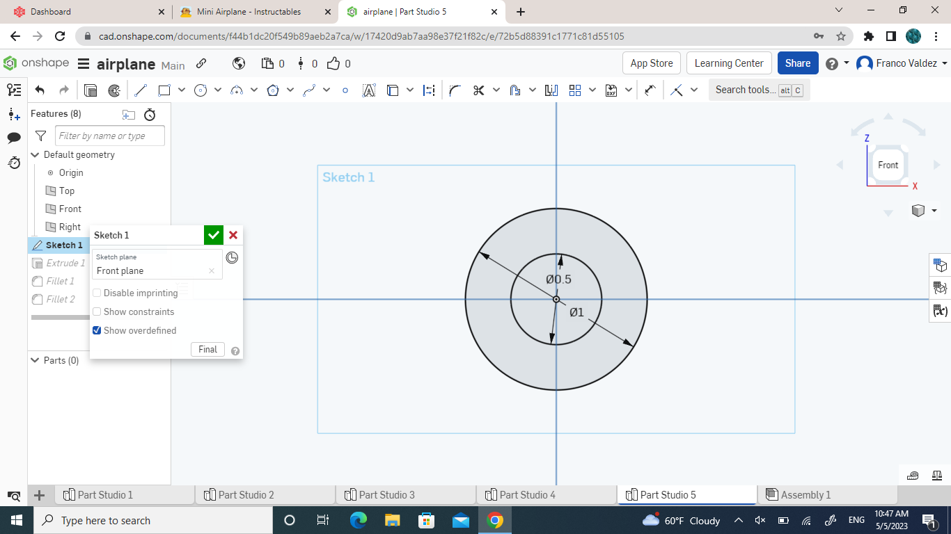
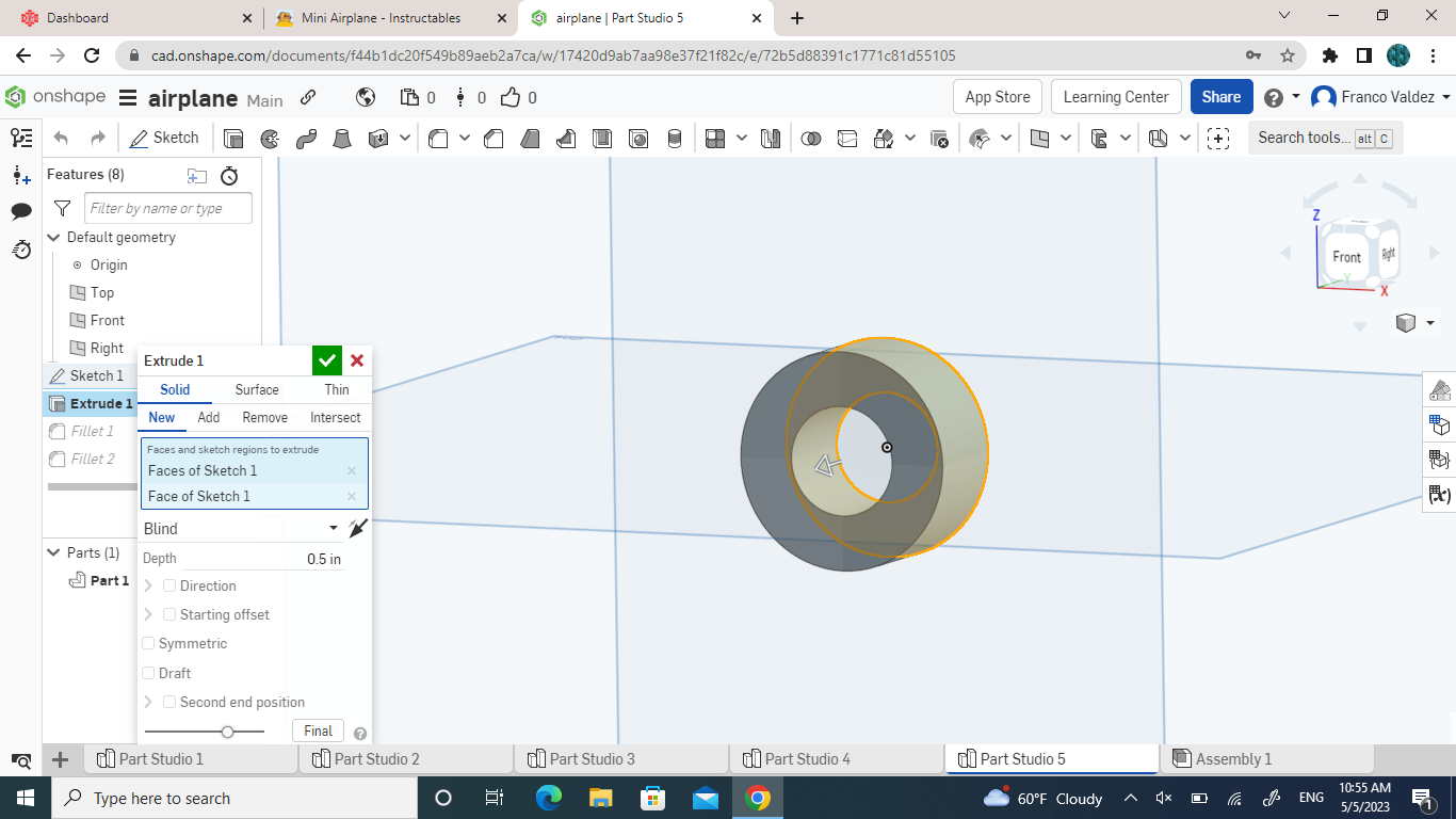
- To begin to make the wheels, you want to make a new part studio and create a sketch on the front plain
- Make two circles from the middle, one with a radius of 1 inch and a smaller one with the radius of 0.5 inches
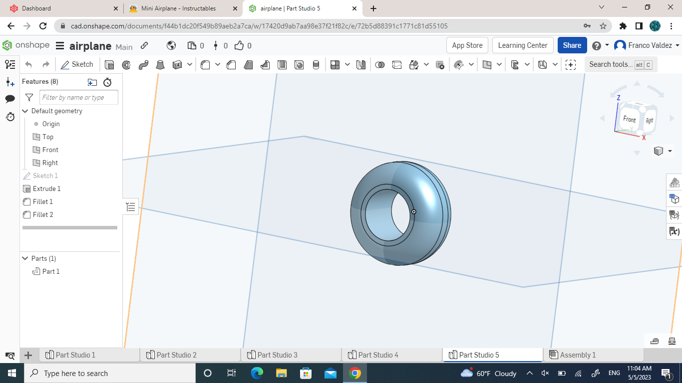
- Once finished with that sketch, you will extrude the outer layer of the circle 0.5 inches
- Then you will use the fillet tool on the left outer edge and fillet it by 0.2 inches
- Do the same thing to the right side
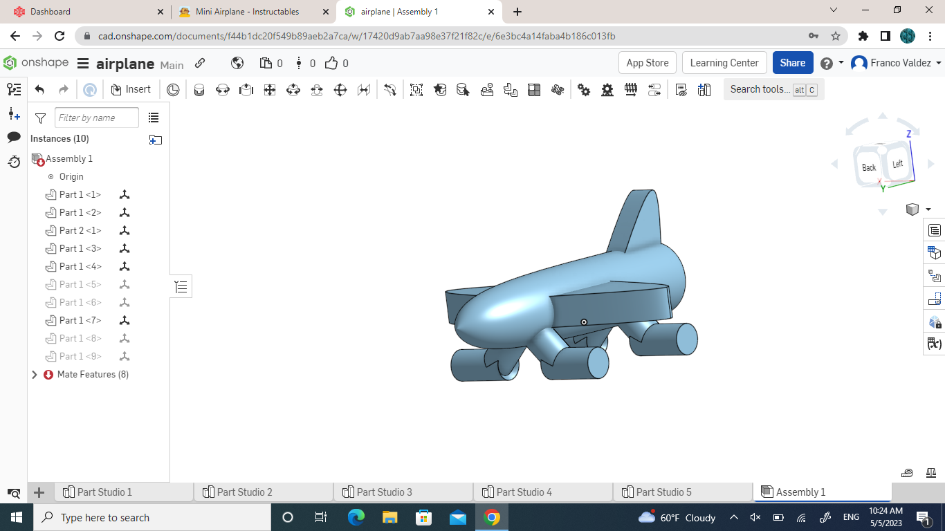
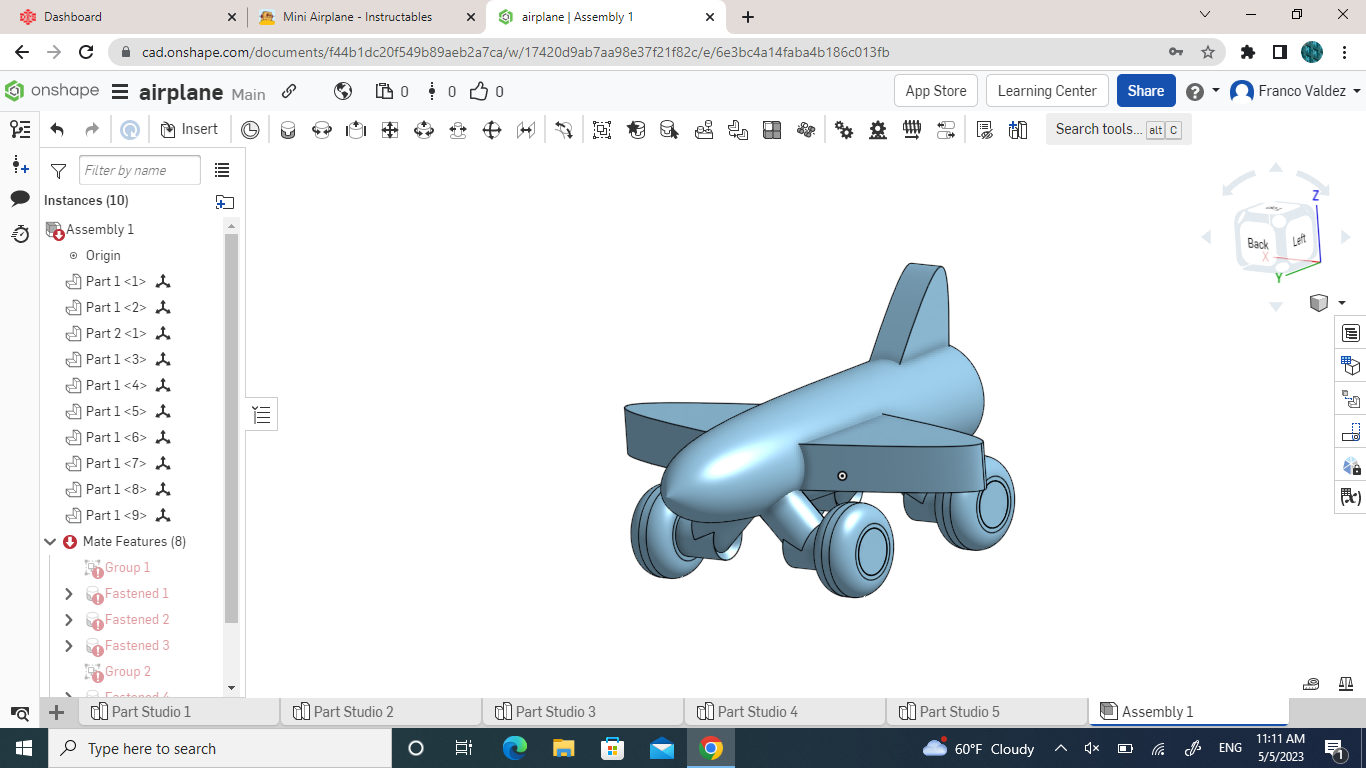
- Insert the wheel 4 times into the assembly page and connect them too each one of the wheel holders on the plane
- Your design for small plane should all be finished now
3D Printing
- For this step you will have to 3D print the model that was created in OnShape, and you will end up with a mini airplane