Design and Build a Glider Using Fusion 360
by Airbus Foundation in Teachers > 3D Design
12487 Views, 44 Favorites, 0 Comments
Design and Build a Glider Using Fusion 360
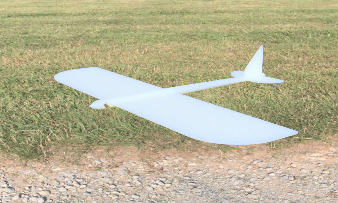

This Instructables tutorial guides through how to design and manufacture your own Airbus Glider! Before we jump into this guide, start by first visiting Airbus Discovery Space where you can find some amazing lessons on why things fly. This will help to inform your glider’s design and help to fly further than the competition.
Using Autodesk Fusion 360, you’ll be taken step by step through the process of how to design and manufacture a glider using a 3D printer, laser cutter or just scissors. There’s multiple ways to design and make your glider so why not try as many as possible to see what works best.
If you’re more comfortable with Autodesk Tinkercad, you can follow the tutorials below:
Getting Started
Instructions:
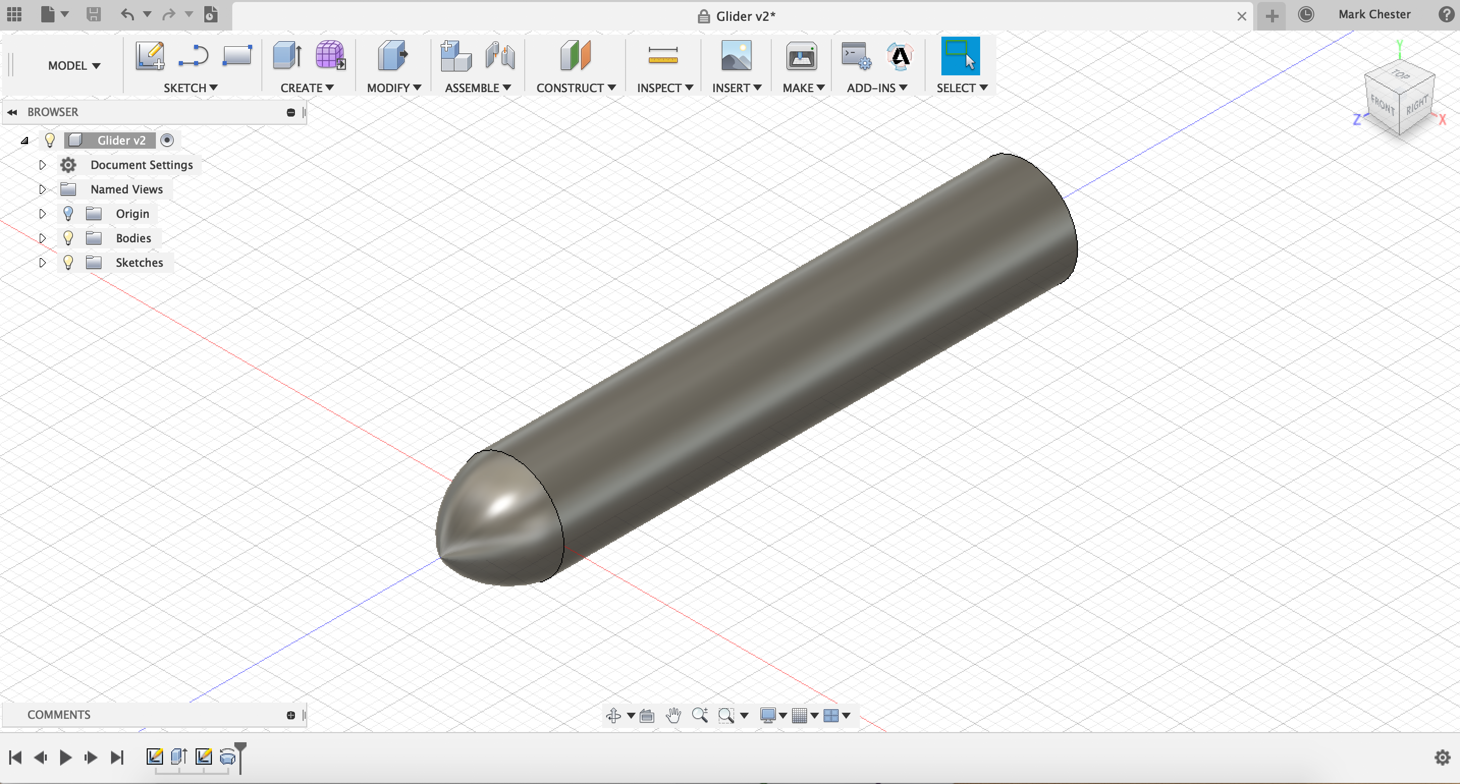
- Start by going to the toolbar and clicking into the sketch menu, then go to create sketch.
- Next, create a sketch on the XY plane by clicking on it, notice how the view cube has changed to the front view.
- Go back into the sketch menu and open the circle menu, select the centre diameter circle.
- Select the origin as the centre of the circle, create a circle 10mm in diameter.
- Once complete, go to the end of the toolbar and click finish sketch.
- Next, go into the create menu and click on extrude.
- Extrude the previously drawn circle by -50mm.
- Now, create a new sketch on the YZ plane, notice how the view cube changes to the right view.
- Using the line tool, create a line going 7mm out from the origin.
- Next, go into sketch and use the project tool to trace around the front edge of the glider.
- Go back into the sketch menu and select the 3-point arc tool.
- Start by selecting the outside edge of the body, then select the end of the line going out from the origin.
- Select a third point on the grid to complete the arc and then finish sketch.
- Finally, go into the create menu and select revolve. Select the profile inside the arc as the profile and the line as the axis.
- Congratulations, you have successfully create the main body of the glider.
Creating a Loft
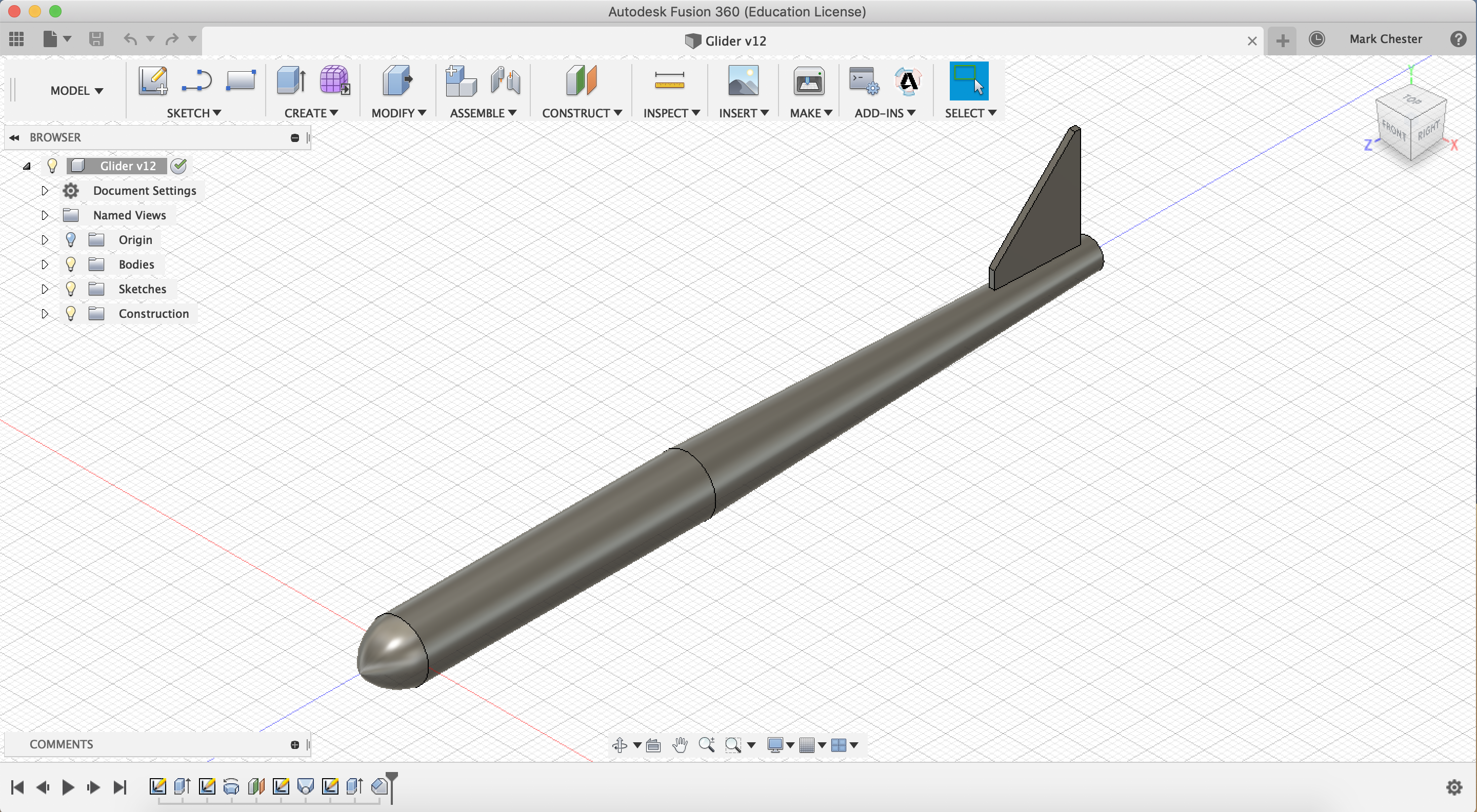
Instructions:
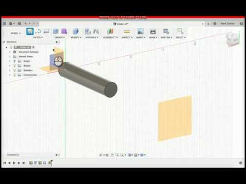
- Start by going to construct on the toolbar and select offset plane.
- Offset the XY plane by a distance of 70mm.
- Create a sketch on the newly constructed plane, notice how the view cube changes to the front view.
- Go back into sketch and select a centre diameter circle, draw a circle on the origin with a diameter of 5mm and finish sketch.
- Next, go into create and select the loft tool. Select the back face of the cylinder as profile 1 and the new circle sketch as profile 2.
- Create a new sketch on the YZ plane, notice how the view cube changes to right.
- Use a 2 point rectangle tool to draw a rectangle with a width of 15mm and a height of 20mm, make sure the first point is a small distance away from the back edge of the glider.
- Next, select the dimension tool under sketch, dimension the back edge of the glider and the rectangle by 2mm.
- Extrude the rectangle rectangle, make sure to change the direction to symmetric, change the distance to 0.5mm and check the operation is set to join.
- Finally, go to the modify menu and select chamfer. Select the top inside edge of the rectangle, chamfer by a distance of 14mm.
Creating the Wings
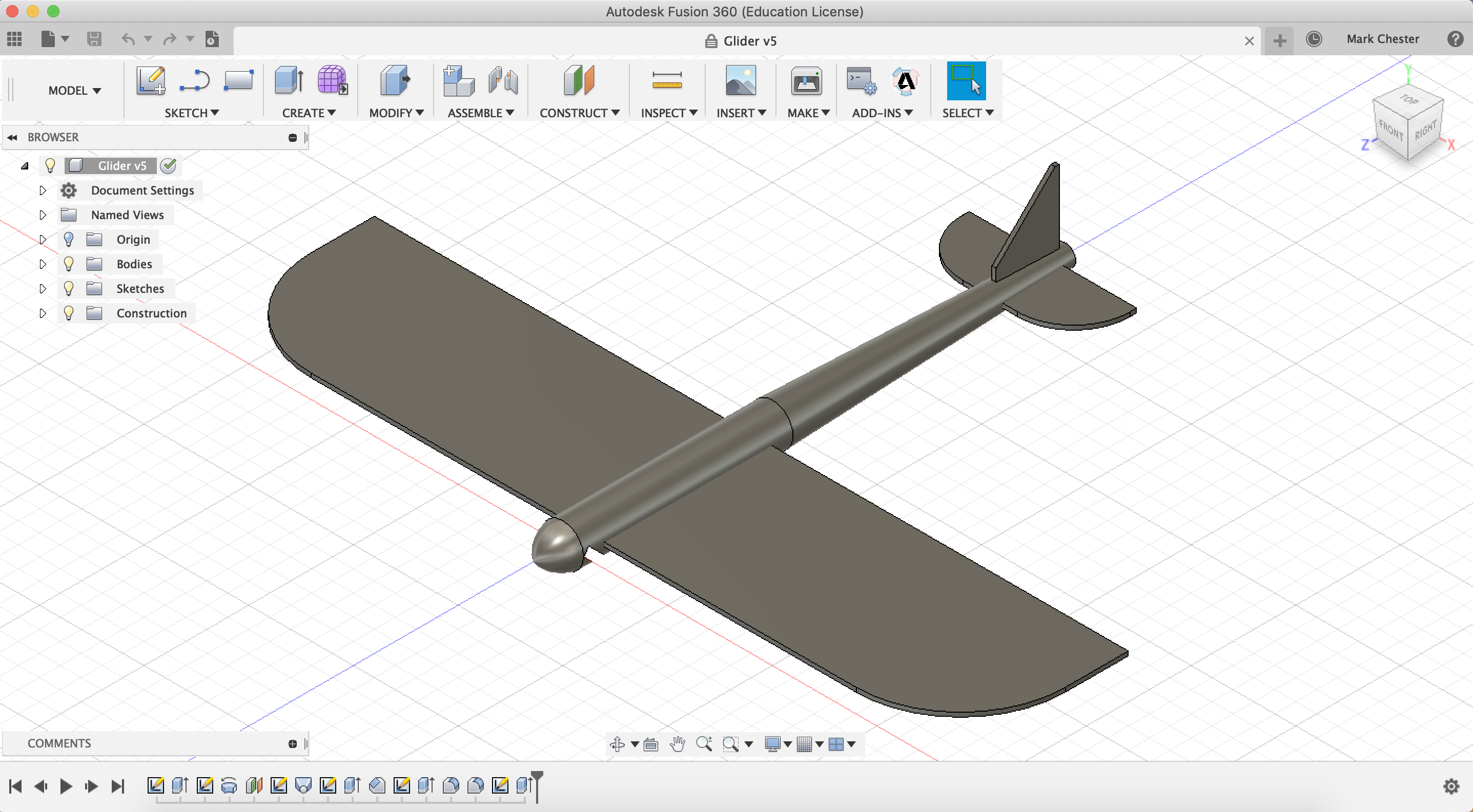
Instructions:
- Create a sketch on the XZ plane, notice how the view cube changes to the top view.
- Using a centre point rectangle, place the centre of the rectangle roughly in the centre of the main body, change the dimensions to 180mm wide, by 40mm high. (This will depend on the size of your 3D printer or laser cutter)
- Next, use the dimension tool to dimension the front edge of the rectangle away from the origin by 5mm.
- Create another centre point rectangle, this time roughly in the centre of the back fin, change the dimension to 40mm wide and 15mm high.
- Again, use the dimension tool to dimension the outside edge of the smaller rectangle from the edge of the glider by 3mm, then stop sketch.
- Use the extrude tool to extrude the wings, change the direction to symmetric and the overall distance to 1mm. Make sure to change the operation to New Body. (This will depend on the thickness of your card.)
- Go into modify and select fillet, use the fillet tool to round the front corners of the wings by a radius of 25mm.
- Again, use the fillet tool to round the front corners of the back wings by a radius of 13mm.
- Create a new sketch on the YZ plane, notice how the view cube changes to the Right View.
- Using the line tool, create a line going on angle of 45 degrees from the origin with a distance of 2mm.
- Then, use a 3 point rectangle to create a rectangle along the line with dimension of 2mm wide and 10mm long.
- Use the extrude tool to cut the rectangle profile, change the direction to symmetric, the distance to 11mm and make sure the operation is on cut.
Preparing for Laser Cutting
Instructions:
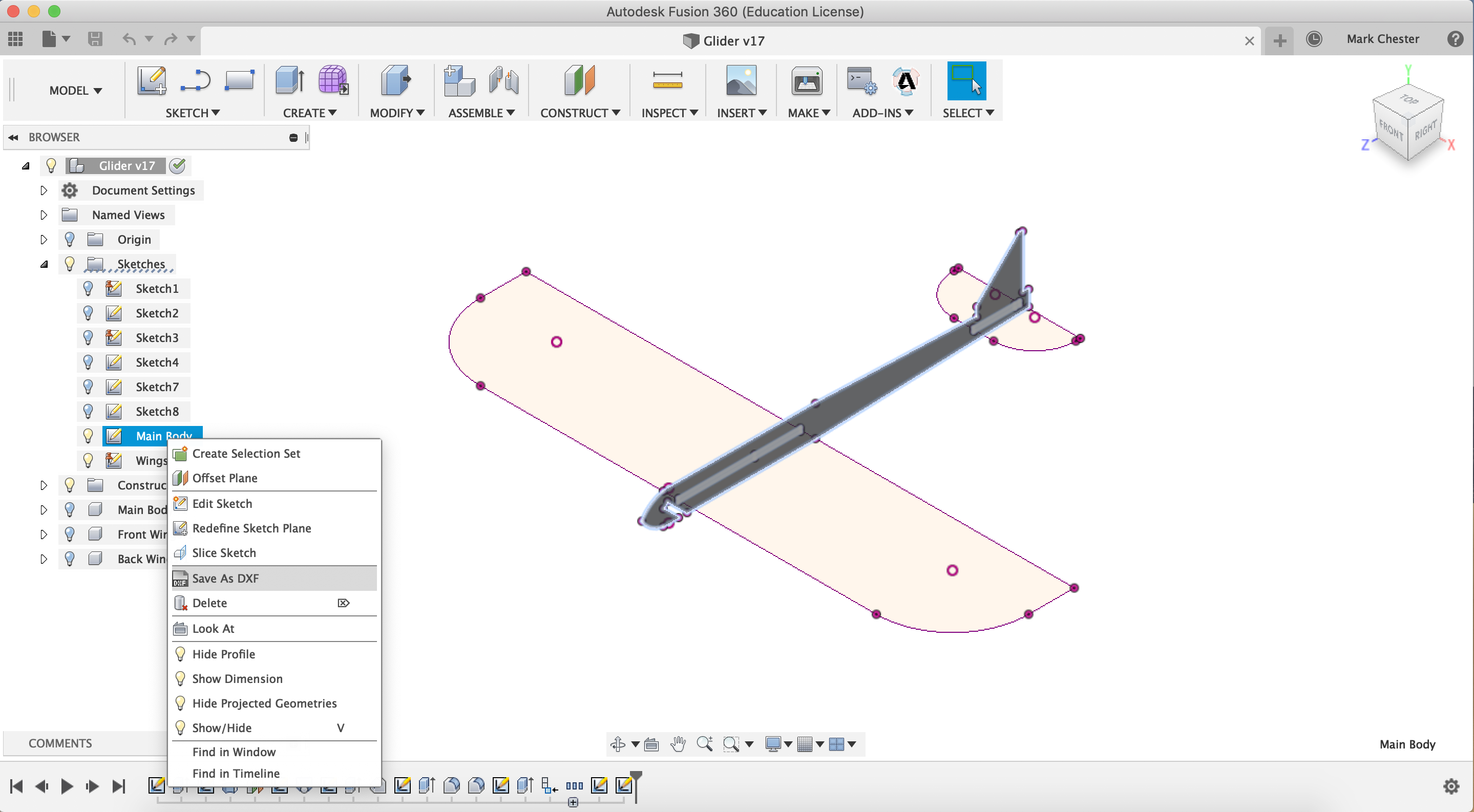
- Go into the Browser on the left side of the screen and open the Bodies folder.
- Double click on body 1 to change the name to main body.
- Repeat this step with body 2 and 3, rename body 2 as Front Wings and body 3 as back wings.
- Right click on the main body and click onto create components from bodies.
- Repeat this step for the Front and Back wings, creating 3 components in total.
- Create a new sketch on the YZ plane, notice how the view cube changes to the Right View.
- Using the project tool, trace around the Main Body of the glider and the Wings, then finish sketch. (You may need to use the offset tool to add tolerance around the wing slots)
- Go into the Sketch folder in the Browser, rename the last sketch Main body.
- Next, create another sketch, this time on the XZ plane. Notice the view cube has changed to the top view.
- Again, use the project tool to trace around both wings of the glider, rename this sketch Wings and finish sketch.
- Finally, to export the sketch as a DXF file, right click on the sketch you want to export in the Browser and go to Save as DXF.
- Tutorials on how to setup a DXF for laser cutting can be found on Instructables.
Creating a Drawing
Instructions:
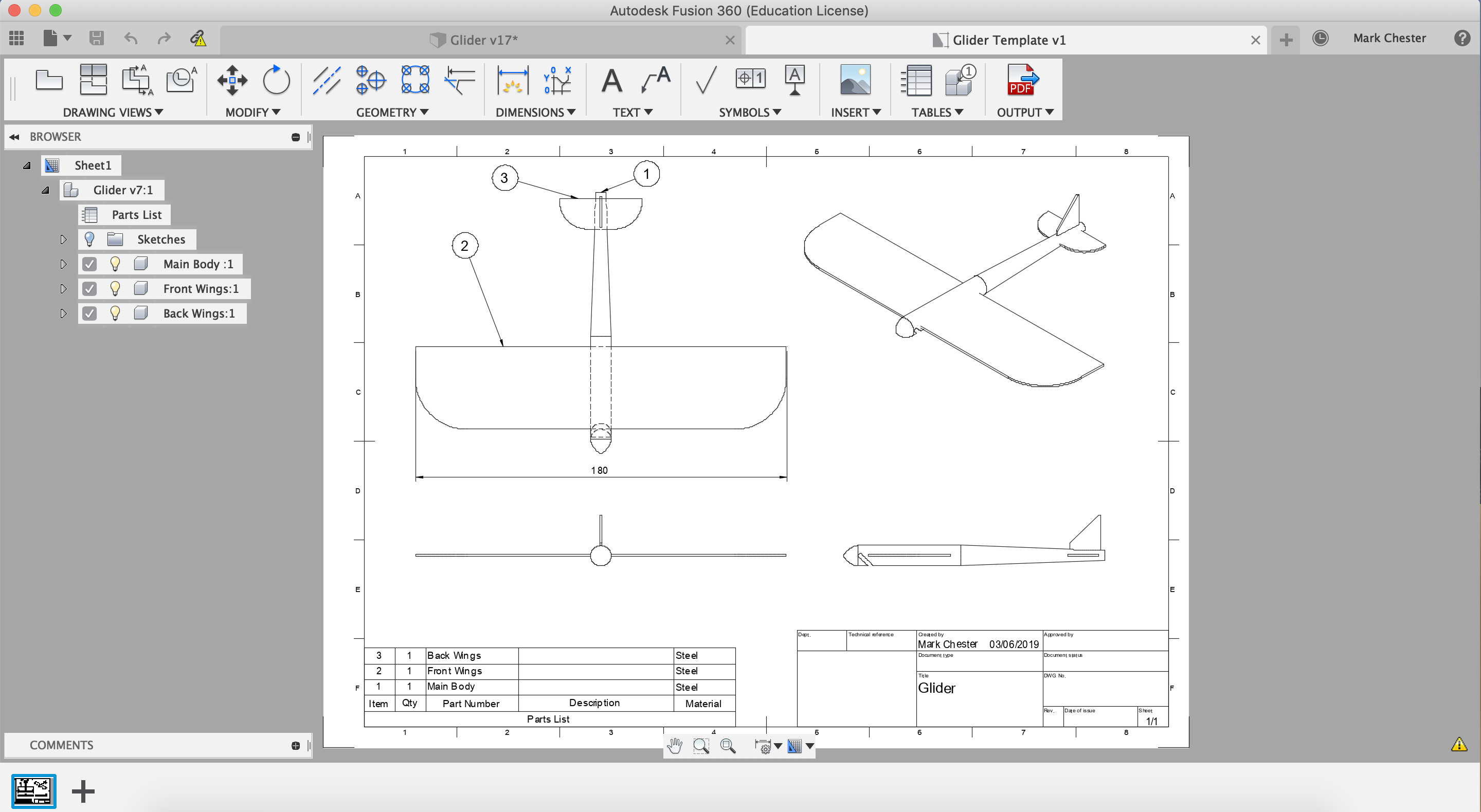
- Go to the start of the Toolbar and click on model, change the workspace to drawing from design.
- A menu will appear called Create Drawing, keep the defaults settings and click OK.
- Start by placing a base view of the glider in the bottom left hand corner of the drawing, change the scale to 1 to 1.
- Next, use the project view tool to add a top, isometric and side view of the glider to the drawing.
- Use the dimension tool to add dimension to your drawing, select an edge, radius or two points you like to measure between.
- Go to Tables in the toolbar, create a table by place it in the bottom left hand corner of the drawing. Notice how it creates a list from the components created earlier.
- Finally, change the Title block in the bottom right hand corner of the drawing by click on the table twice.
- To print the drawing, either go to file and then print or export the drawing as PDF.
Preparing for 3D Printing
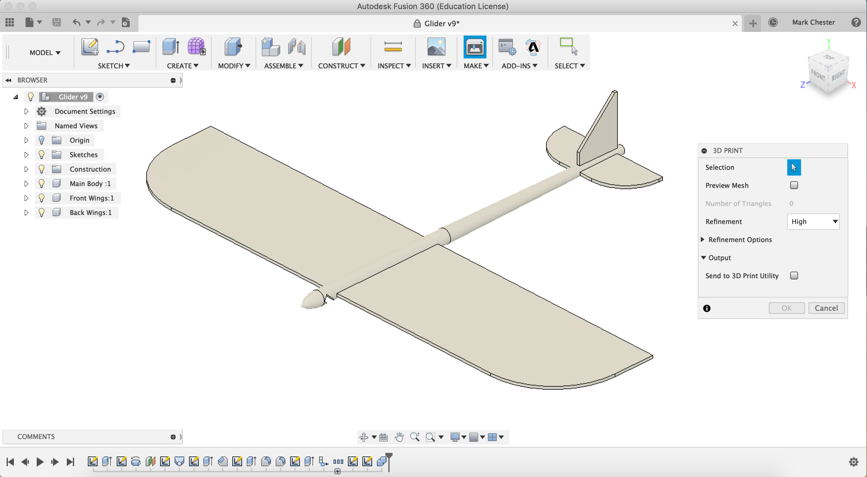
Instructions:
- First, go to modify and then Physical Materials, in the materials library go into plastic and find ABS plastic, click and drag this on to all three components. Make sure to close the Physical Materials Library by click close.
- Next, go to the top of the Browser and right click on the top line. Then end up properties to view the weight of your design.
- To reduce weight, go into the first sketch and change the dimension of the circle to 5mm in diameter. Notice how the size of the glider changes when you click finish sketch.
- Also, go back into the third sketch in your design and change the dimension of the circle to 3mm in diameter.
- Go back in to properties and measure the weight of your design, notice how the weight has reduced.
- Next, go into modify and then combine. Select the main body as the target body and the wings as the target body. Make sure the operation is set to join.
- Finally, go to make in the toolbar, then 3D print. Select the glider as the object to export. Change the refinement of the STL to high for better resolution.
- Tutorials on how to setup a STL file for 3D printing can be found on Instructables.
Flow Design
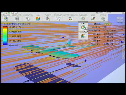
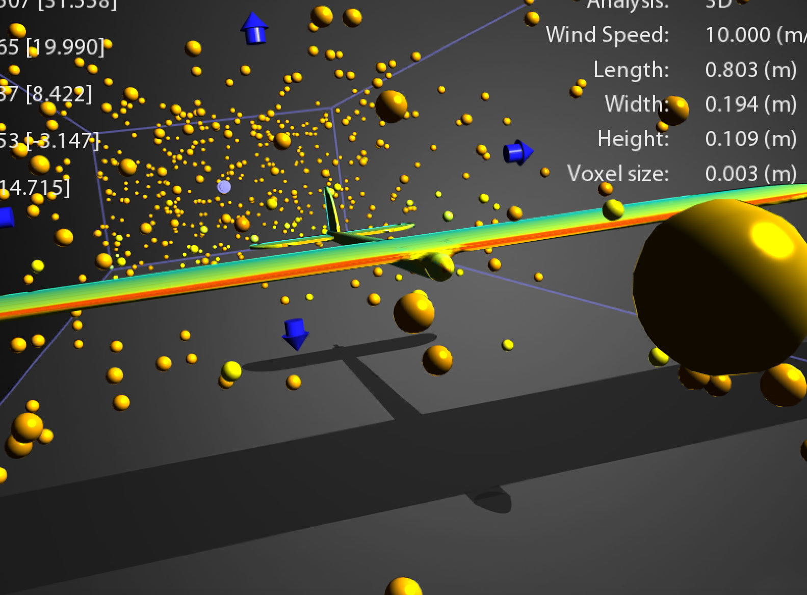
Instructions:
- Download Autodesk Flow Design by following this link. You will need an Autodesk Education Account. (Please note this software is only available until 2020.)
- Open Autodesk flow design, then import the STL export of your design into the software.
- You will need to change the orientation of your design so it is following the direction of the air flow.
- Analyse how air flow interacts with the design of the glider.
- Improvements can be made to the glider in Fusion 360 and then brought back into Flow Design.
Design, Iterate and Build!
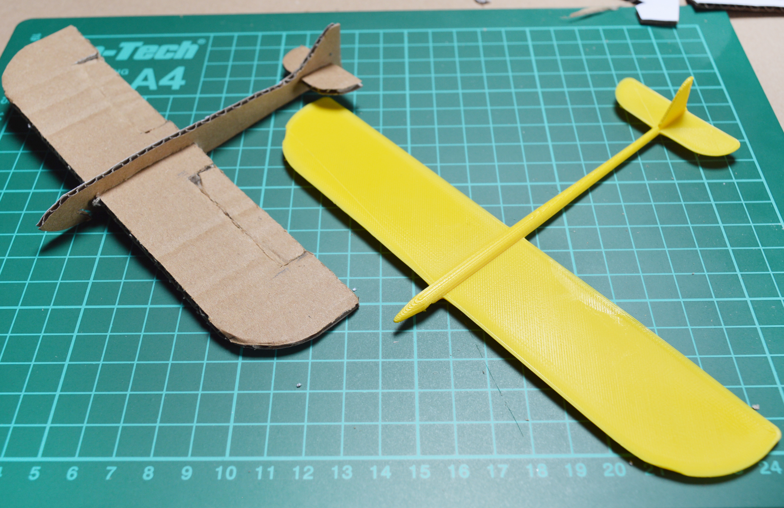
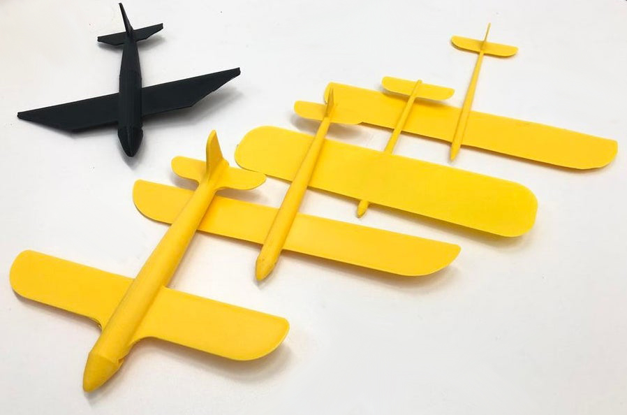
Once you've completed your first glider, try changing the design using Fusion 360. Why not also try using different ways of manufacturing your glider to see which method works best.
Why not try downloading one of the example STL or DXF files? Make sure to share your glider with us, thank you for watching this tutorial. Happy gliding!