Design a Moon Rover in Fusion 360
by Airbus Foundation in Teachers > 3D Design
7939 Views, 7 Favorites, 0 Comments
Design a Moon Rover in Fusion 360
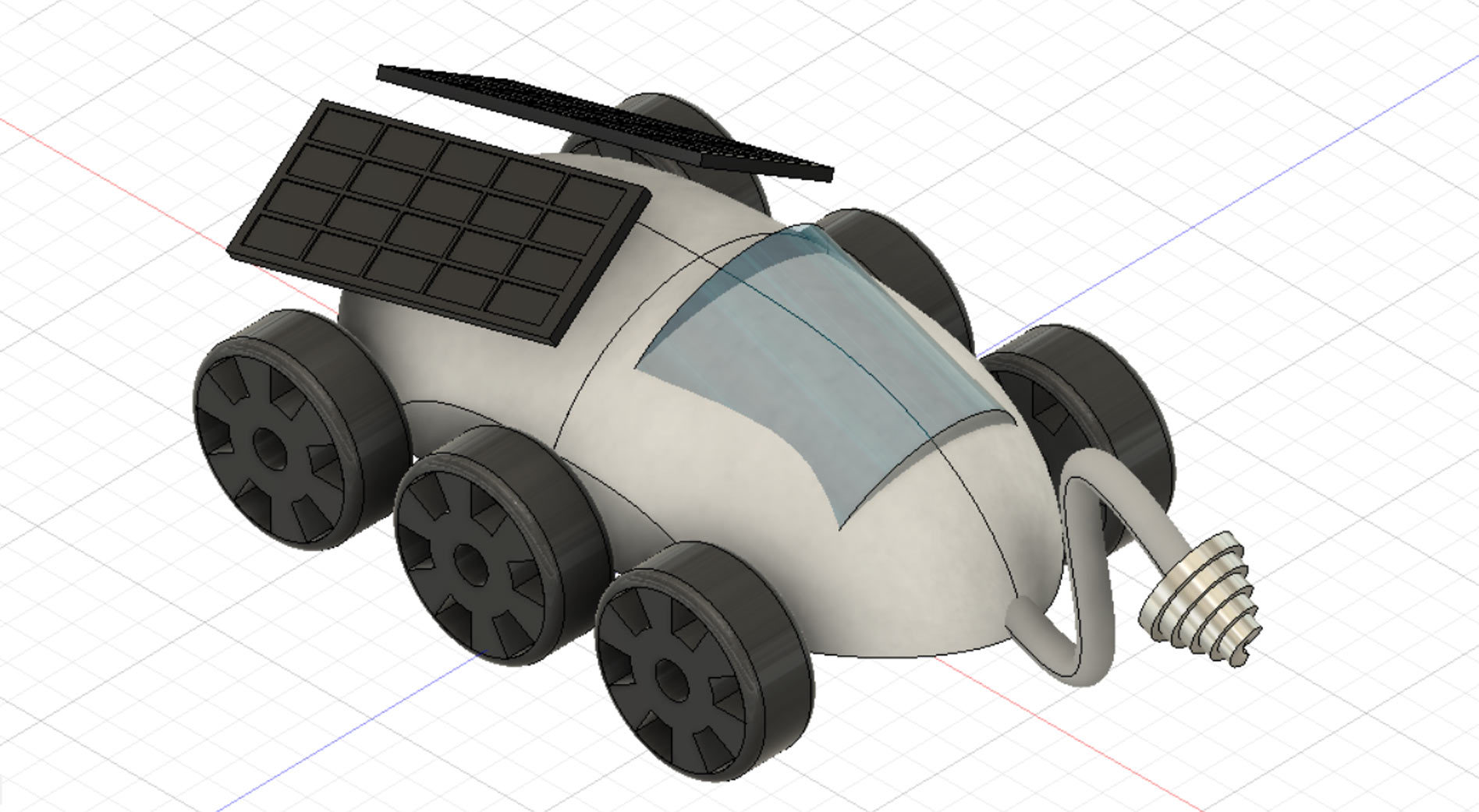
The bumpy and unpredictable terrain of the Moon’s surface necessitates rugged vehicles for commuting, cargo transport, and exploration – and helper robots will need sturdy construction, too! Design your own Moon Ranger and purpose – build it for any mission you can imagine!
Your Daily Commute on the Moon
What’s the best way to travel on the Moon with rocks, boulders, and craters in our way? And when settlements expand, what will our lunar infrastructure look like?
The future of space travel lies in the hands of designers and engineers, just like you. In this Instructable we'll explore designing a Moon Rover using Fusion 360, a professional computer aided design program that has everything you need from parametric design to rending your final design.
Below is the Moon Rover design we will be making together. Take a moment to interact with the model below and see it from all angles before we get started.
The moon is closer than ever with new advancements in space technology. The next breakthrough in space design could come from a designer such as yourself. Let's get making this Moon Rover!
Sketch Body
Start by downloading Fusion 360, and making a free account.
Fusion 360 works by creating 3D models from 2D sketches on a workplane. Since Fusion 360 is parametric, you can make changes to your sketches at any time and the 3D shapes derived from those sketches automatically updates to he new values. You may find using this feature helpful if your design isn't working the way you want.
For this Moon Rover we'll start by designing the body, then attach parts to that.
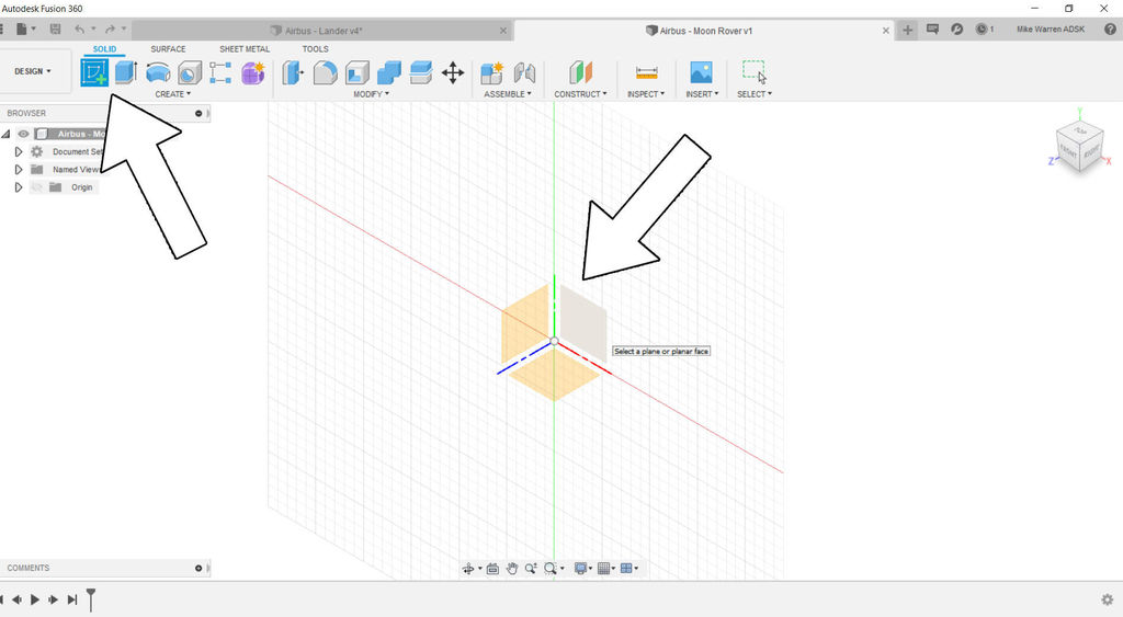
Start by creating a new sketch, then selecting one of the vertical work planes to start your sketch.
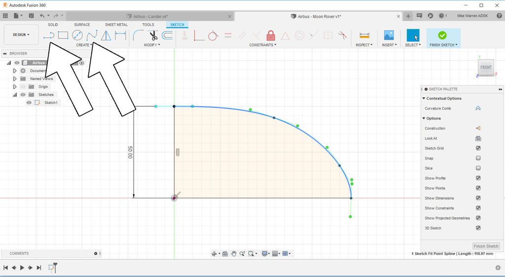
With the sketch interface started, you can start designing in 2D like most CAD software and create your shape outline. W'll use this outline shape to generate 3D geometry later. Start by making a curved shape with a right angle joining the ends. With the shape closed the sketch changes to a pale yellow to show the geometry is closed. In the image above, I used the line and spline tools to create the shape.
When you're happy to the shape click finish sketch on the right side of the top toolbar to finish sketching andreturn to the solid modeling interface.
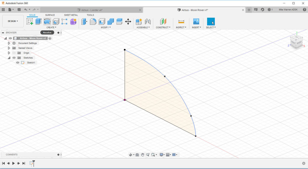
moving around our sketch we can see it exists in 3D space as a 2D drawing. To create the 3D shape we'll use the create tool menu.
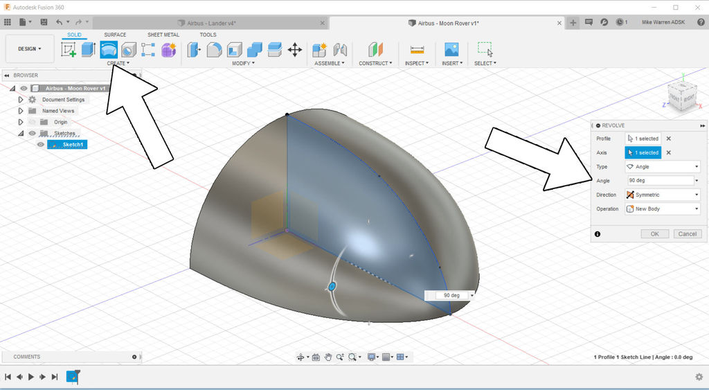
We want this sketch to be revolved around an axis to create the shape. Find the revolve command and chose the sketch as the profile. In the revolve menu that pops up you can select which axis to revolve around, the angle to revolve, and the direction (one side or symmetrical). For this model we want to revolve around the bottom axis, 90 degrees and symmetrical, which will do 90 degrees on both sides of the sketch. Click OK to finish the command.
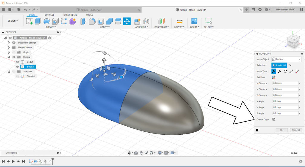
This is only half the Rover body. To create the other half we can select the body (likely Body 1 in your design) and then find the move command located in modify > move/copy, alternatively you can press M on your keyboard as a shortcut. In the move/copy menu ensure the create copy button is selected.
Arrows will appear on your model body allowing you to move the copy. We will want to rotate this body bu using the circular icons that appear outside of the arrows on the body shape. Use rotate to turn the copy 180 degrees and complete the other half of the Rover body.
Rover Body
The current shape for the Rover is decent, but could be a little more refined. We'll shave the sides off this shape to make the body narrower.
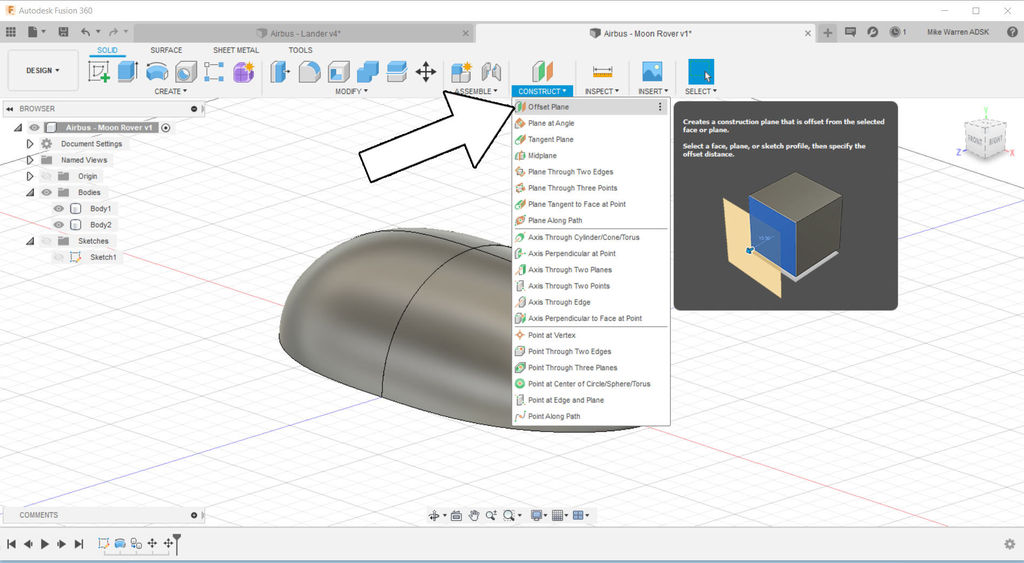
To slice off the sides we start by making a new plane for us to reference, this can be found in construct > offset plane in the toolbar.
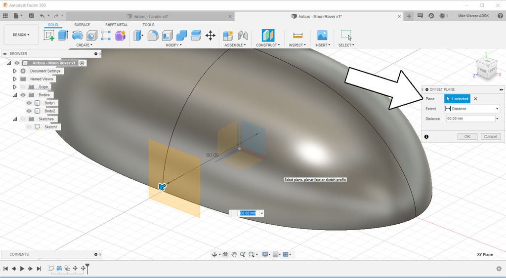
The offset menu lets us chose which plane to use as the offset, and the distance away from the plane we want the offset to be. I chose a distance that was a little outside the edge of the Rover. Click OK to finish the command.
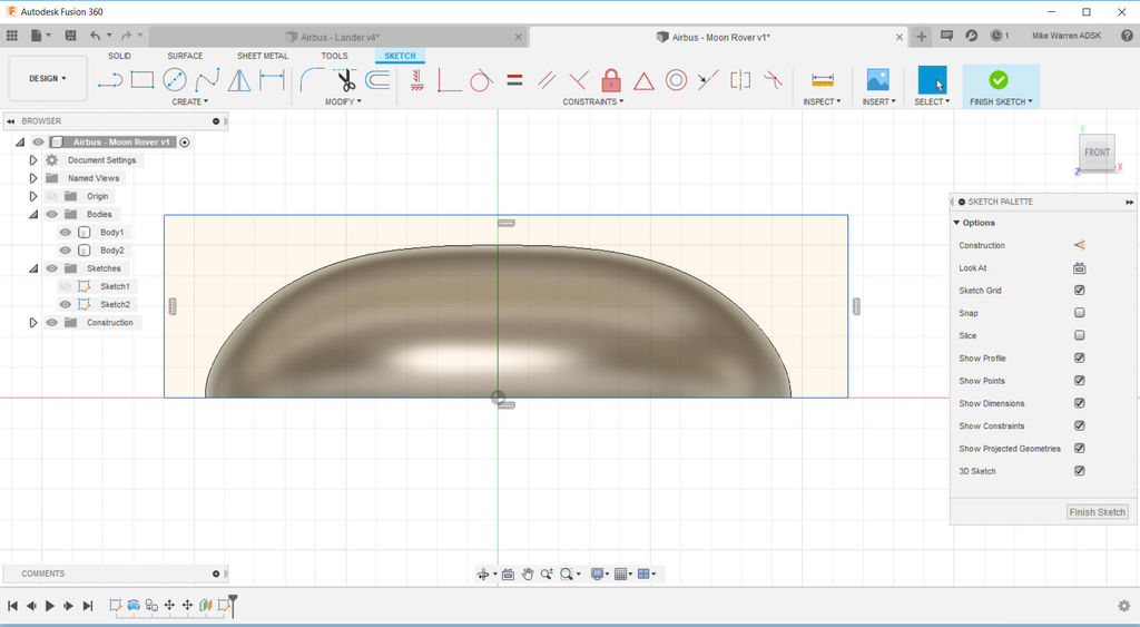
There is now a new plane we can select when we start a new sketch. Click new sketch and then click on the offset plane as the plane we wish to sketch on. The view will change to look at our model from the side. Sketch a rectangle that is wider and longer than your Rover, then click finish sketch to end this sketch. In the model workspace chose extrude and extrude the rectangle shape away from your model.
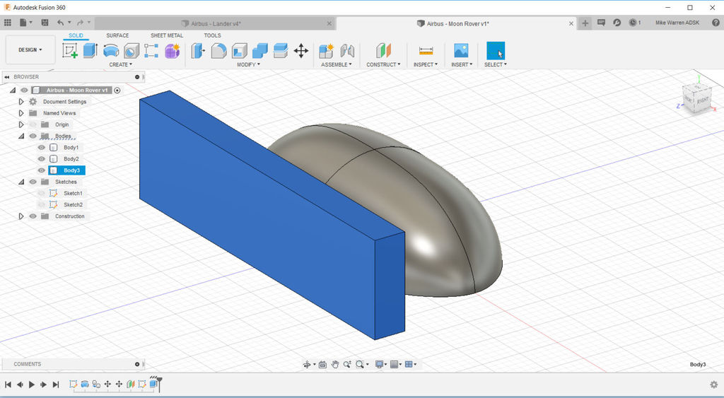
f
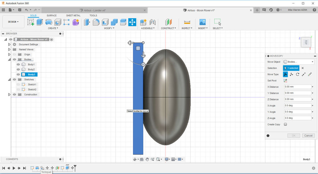
Chose move (shortcut key M) to rectangle close to your Rover body, overlapping the side we want to cut off.
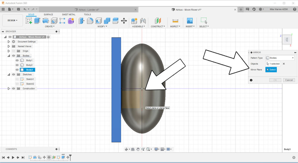
We'll make an exact copy of this rectangle so we can shave off the other edge. Find the mirror tool in create > mirror and use the center line of the Rover body as the mirror plane. Pressing OK will finish the command and create a copy mirrored on both sides of the Rover body.
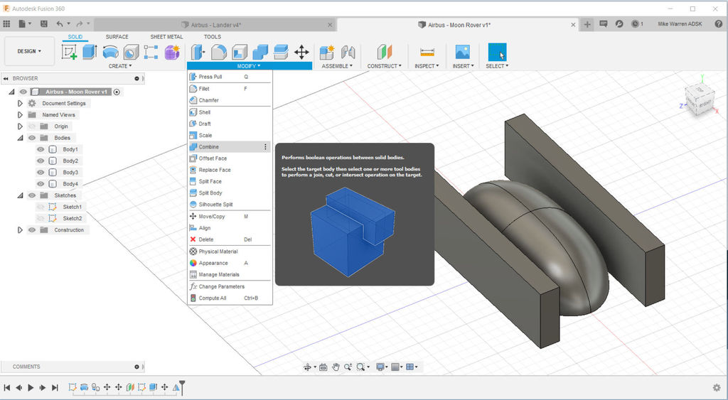
We will use these two rectangle shapes to shave the edges from the Rover by using the combine command, found in modify > combine.
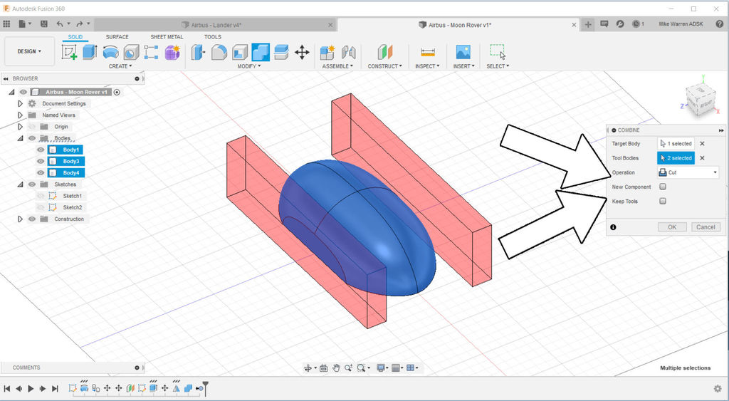
This operation lets us determine which body to keep (the target) and which bodies to use as the removal (tool bodies). Select the Rover shape as the target, and both rectangles as the tool bodies. In the dropdown we want to use the cut operation to cut into our target shape.
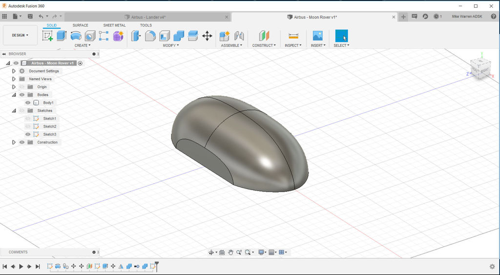
Click OK to finish the command and see the result.
Wheel Design
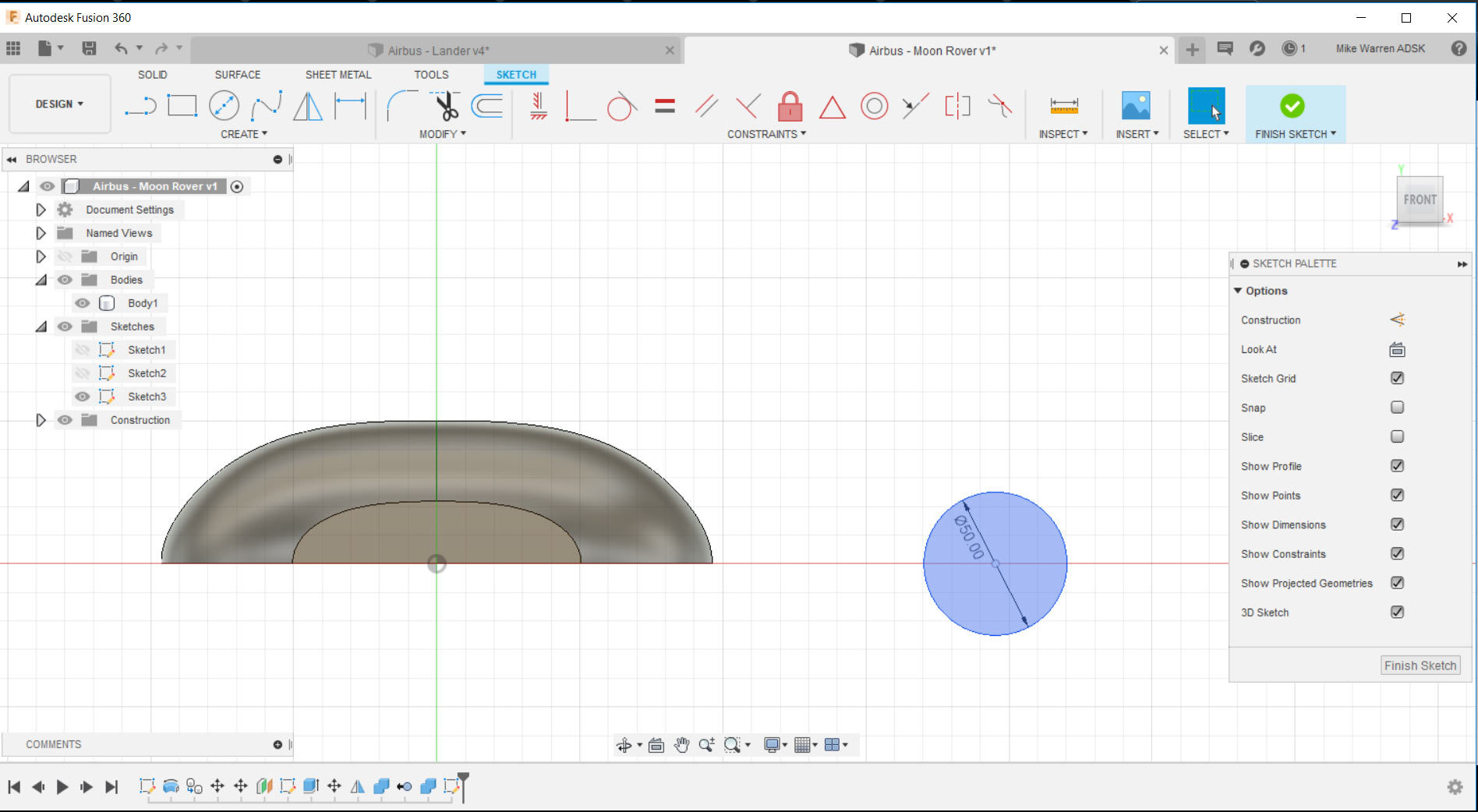
With the Rover body finished we can turn to designing the wheels. Start a new sketch using the same plane as before to make the Rover body.
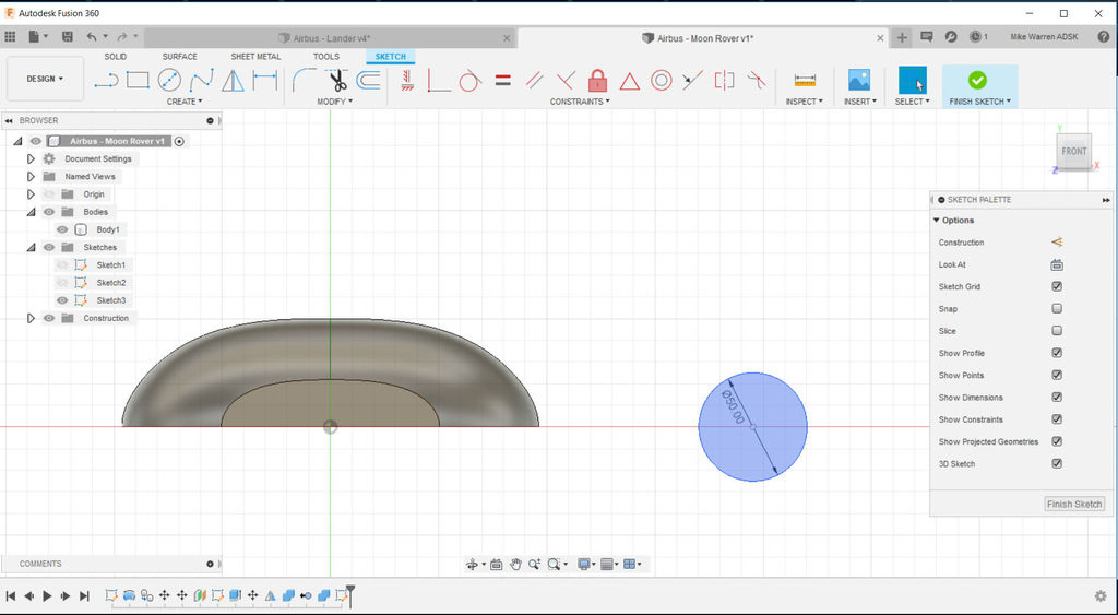
Sketch a circle, which can be found under create > circle or by using the shortcut key C. Draw a circle the diameter of your wheel, using the Rover body for scale. Draw a few more concentric circles to build up the wheel geometry (see image below).
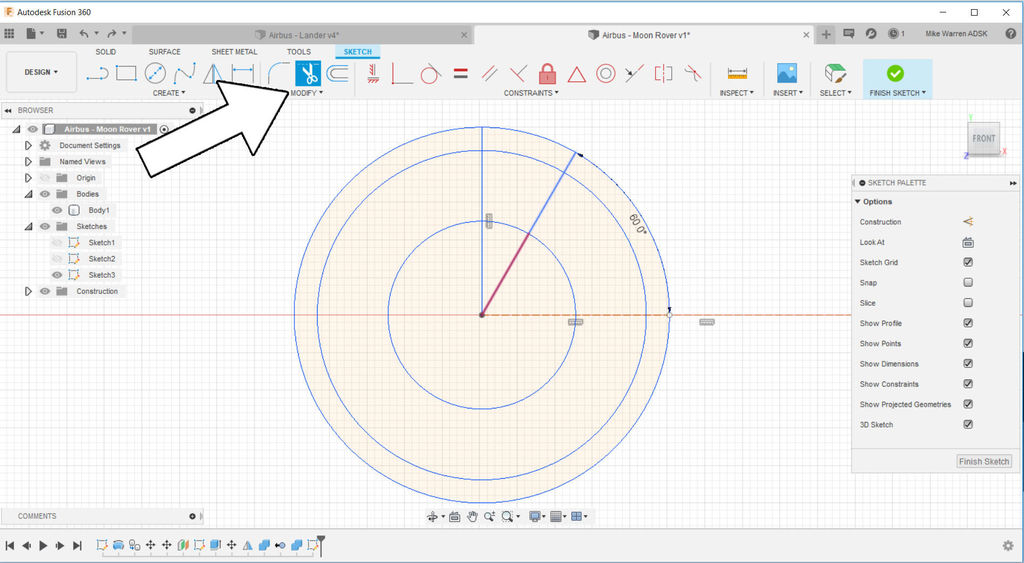
Use the line tool to create radial lines from the center of your circle, these will be used to create openings in our wheel design so it's not a solid puck shape. Extra lines can be trimmed using the trim tool and hovering over the lines to trim, they will turn red which then you can click to delete.
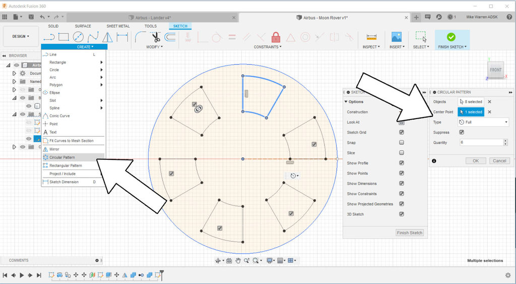
I made one opening design I liked and then used the create > circular pattern to make an array around the wheel. When you're satisfied with your wheel shape click OK to finish the command.
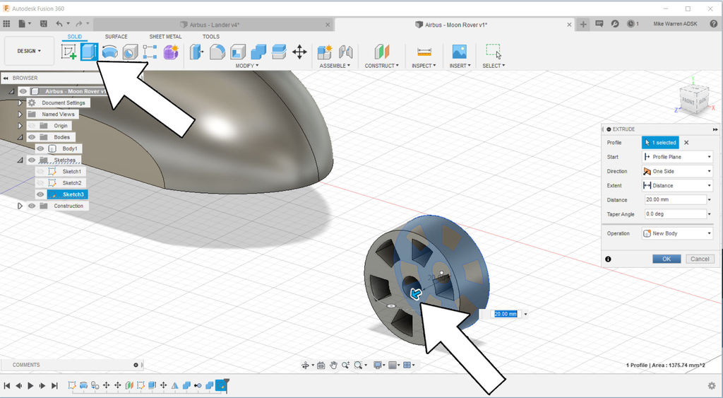
back in the model workspace use the extrude command to pull the wheel sketch into a 3D shape. Click OK to finish the shape.
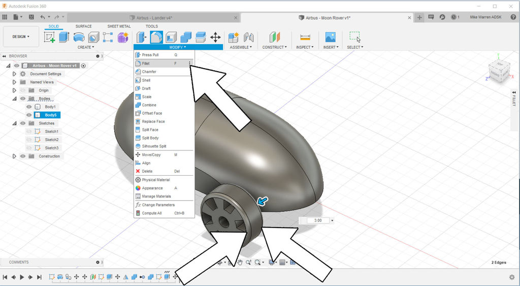
To get a smoother edge on my wheel I used the fillet command found under modify > fillet. Click on the edges you want to fillet and then drag the mouse inwards to create your desired fillet.
Multiply Wheels
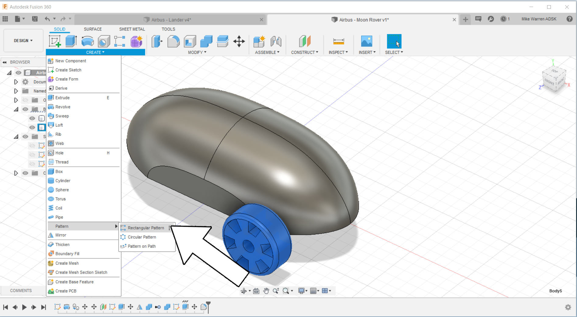
With our wheel design complete we can move the wheel into it's desired location on the Rover body. You can move the wheel anywhere on the body, but to use the pattern tool the wheel can't be in the middle of the body.
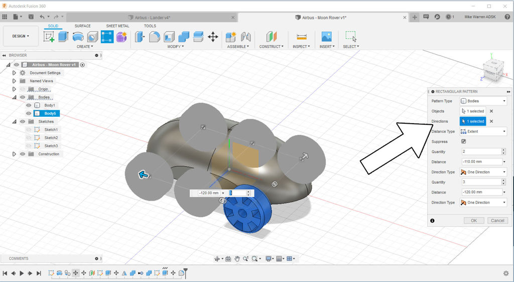
With the wheel in position we will use the create > rectangular pattern tool to make an array around our Rover. In the rectangular array menu you can specify the number of wheels, and the distance apart on each axis.
Since the wheels I made are symmetrical the rectangular pattern was a good choice. If your wheels are different on both sides you can do the rectangular pattern command on one side, then try the mirror command to flip a copy onto the other side of the Rover.
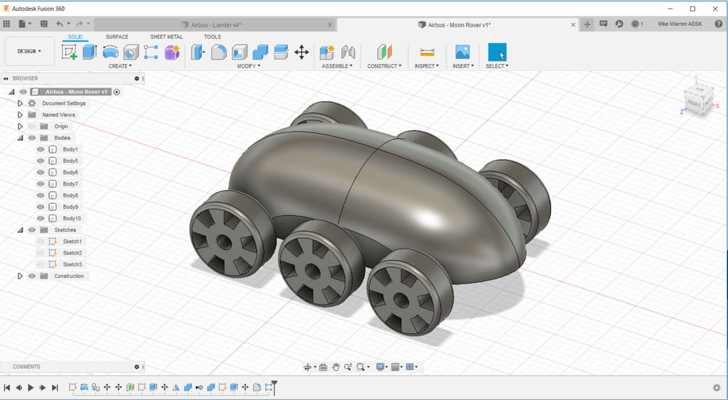
Here is what my Rover design looks like at this stage.
Solar Panels
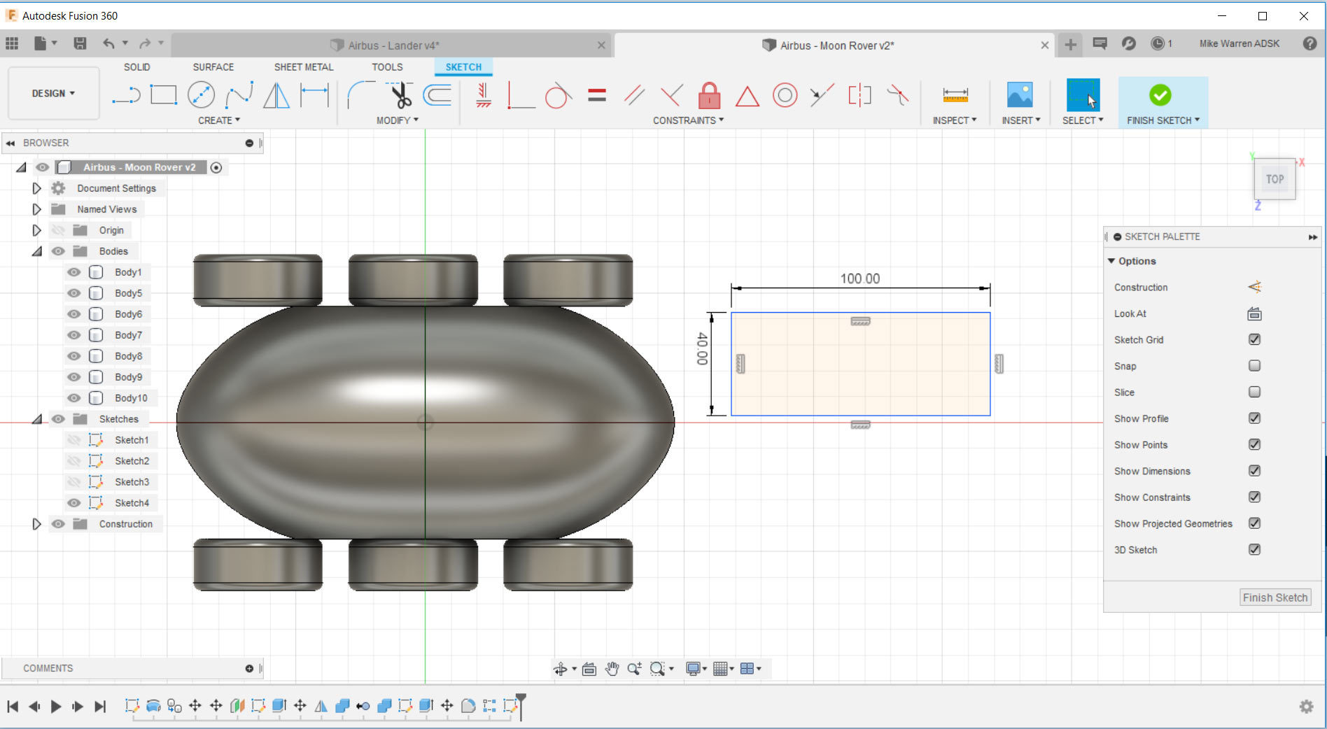
This Rover uses solar panels on the back to stay charged. To make these panels I started a new sketch, using the ground/floor as my workplane.
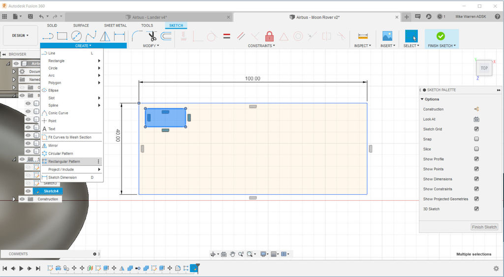
A large rectangle was drawn to be the outside of the solar panel. You can resize this rectangle any time by clicking on the measurement values on the outside of the rectangle and putting in a new value.
A smaller second rectangle was drawn inside the large rectangle, this will be one of the solar cells. We'll make more using the rectangular pattern tool to fill out the solar panel.
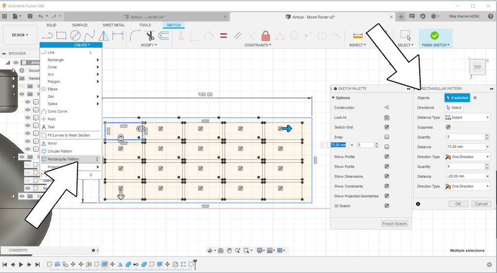
Using create > rectangular pattern to fill the solar panel outline with the solar cells. Use the small rectangle as the object and then move the arrows on the shape to fill out the panel with your desired cells.
Click OK to finish the sketch and return to the model space.
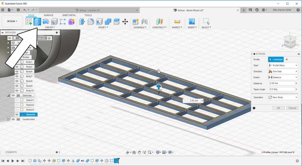
Next, extrude the panel shape to create a raised area for the solar panel. Since this is only a model we only need to visually show a difference between the outer shape of the panel and the cells inside. I chose to do this by extruding just the panel and not the individual cells. Click OK to finish the command.
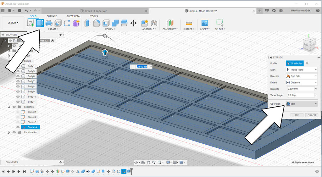
Now use extrude again to extrude the individual cells, but a little shorter than the solar panel. This will give the cells definition. Make sure the join operation box is selected, this will join the solar cell extrusion to the solar panel outline we just make. Click OK to finish the command.
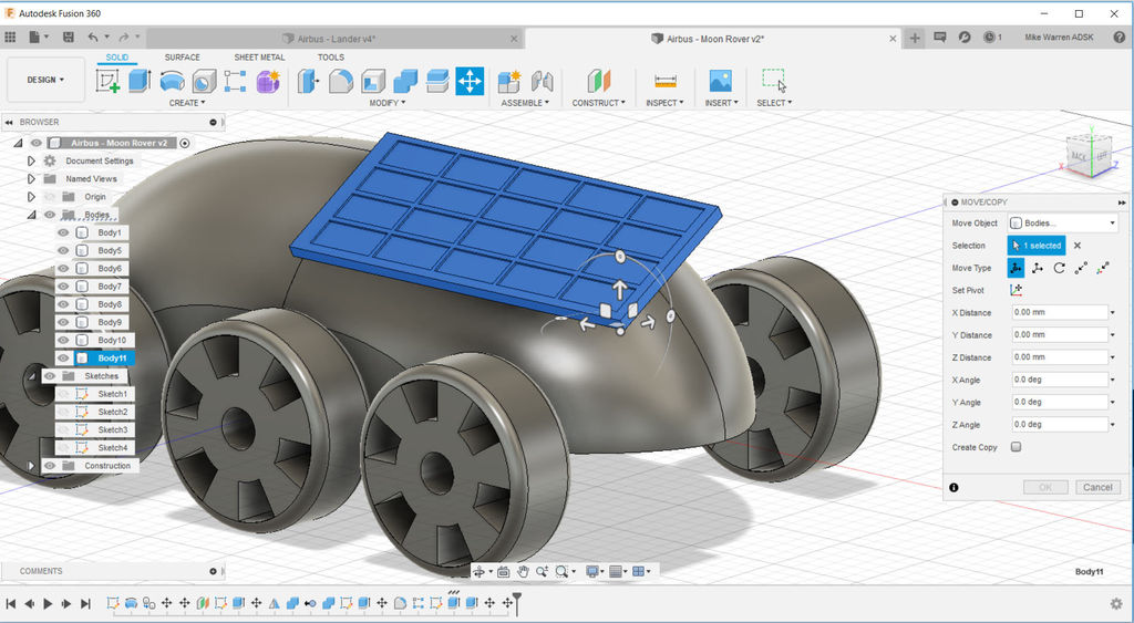
Use the move command to move the solar panel onto the Rover. It doesn't have to touch the Rover body, partly because we'll be adding more parts between the Rover and the solar panel, and partly because this model is a design only and not meant to be functionally complete.
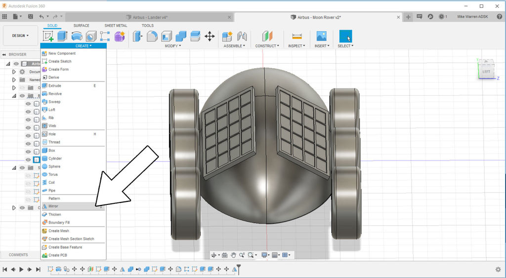
The last step to do here is mirror the solar panel to the other side of the rover to have two.
Cockpit
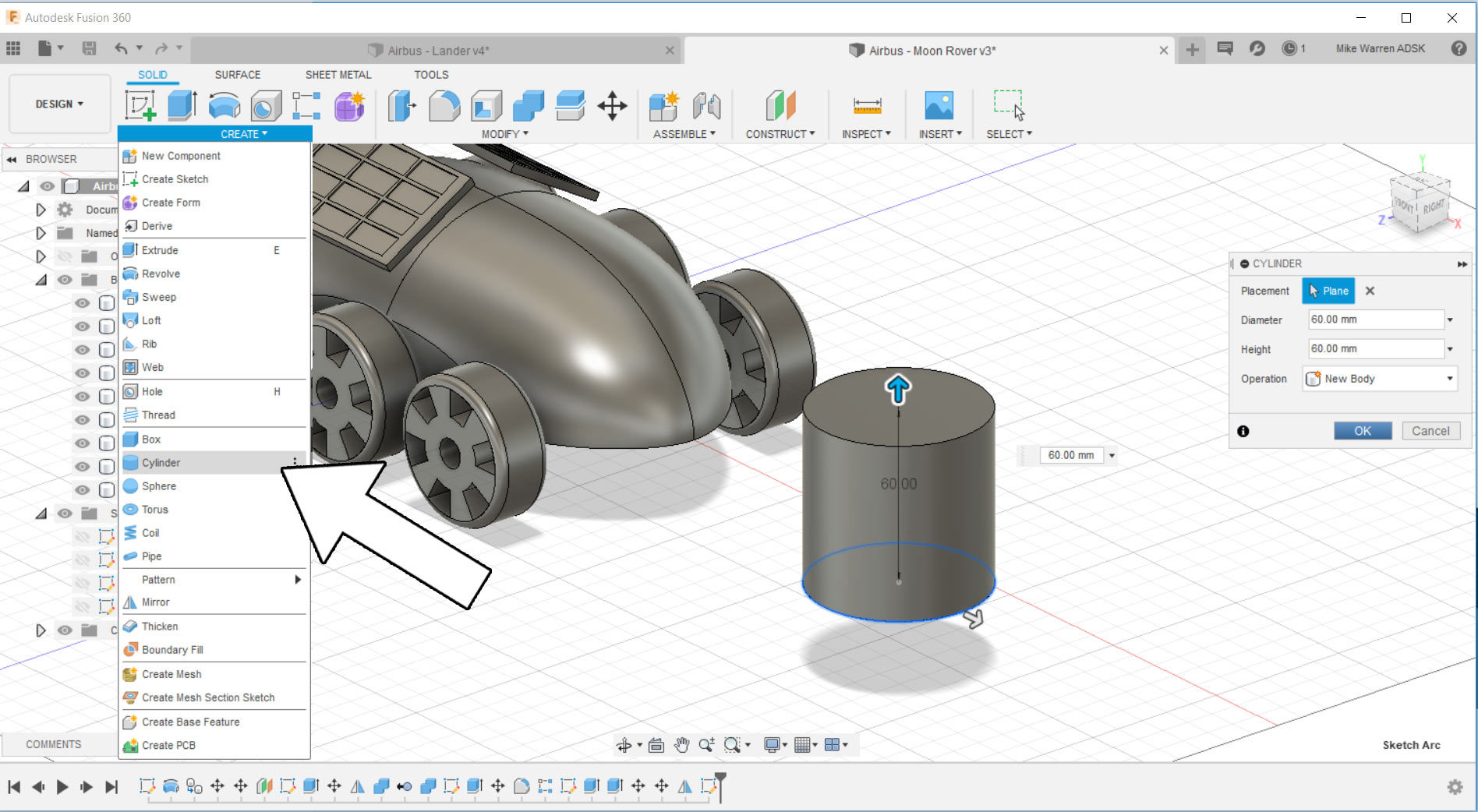
Next we'll add a place for our Rover driver to sit. To keep things simple I deceided to use a cylinder as the cockpit shape. Make a cylinder by using create > cylinder, then draw on the floor plane a circle that will be the bottom of the cylinder, after you will be prompted to pull the cylinder upwards to create the shape height.
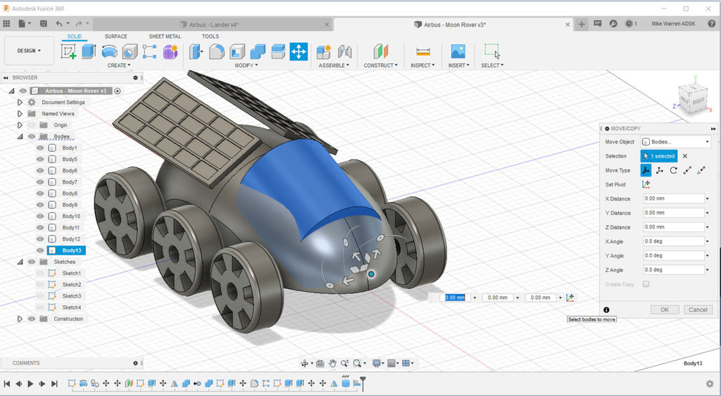
Move the cylinder over the Rover body and rotate to make a cockpit shape. If you find your cylinder is too long you can always shrink it down using the press/pull found under modify.
It may look like a solid block right now, but we can apply a material to the cockpit later to make it look like glass.
Wheel Axle
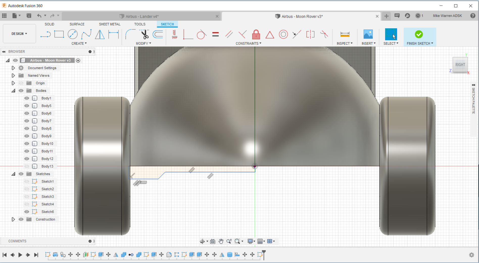
We have wheels for this Rover, but will need an axle for them to ride on. This is an optional detail, but I think it's important as it's a visible element in our design, and it helps keep our CAD skills sharp.
Start a new sketch on whichever plane allows you to look at your Rover head-on. I made a simple sketch for my axle that is wider on the end closest to the wheels. I only need to draw a small part of this axle, as well by using the revolve command to turn the profile into a round axle, and then the mirror command to extend the axle to the other side of the Rover and connect the wheels.
Finish the sketch to return to model space.
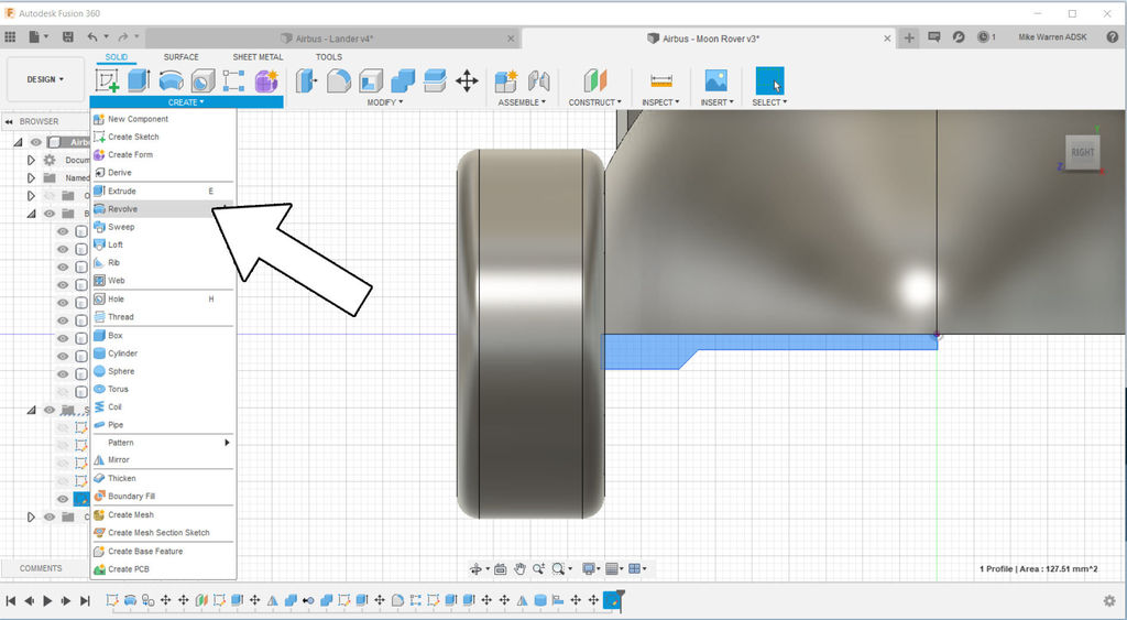
We'll use the revolve command to turn the axle sketch into a round axle.
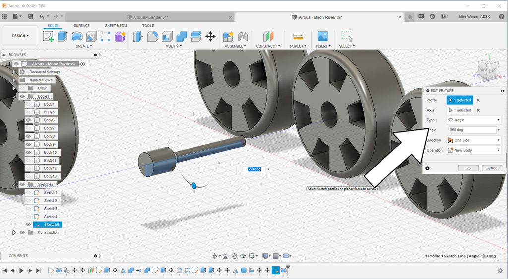
Use your sketch as the profile and then set your angle to 360°. Chose the new body operation and then click OK to complete the action.
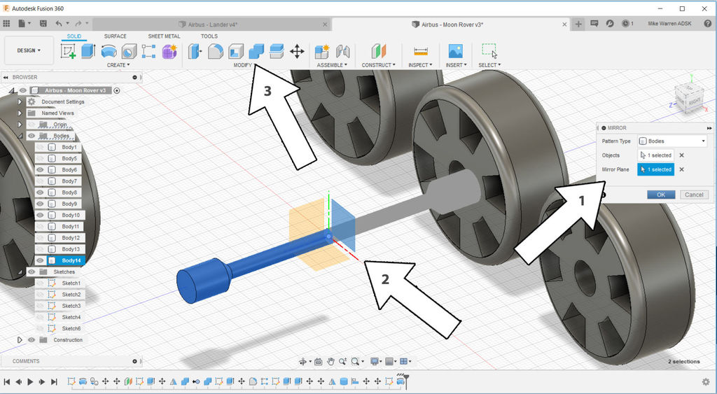
Using the mirror command again, select your new axle body and mirror along the Rover center line. Lastly combine the two axle halves to make one axle that connects both wheels.
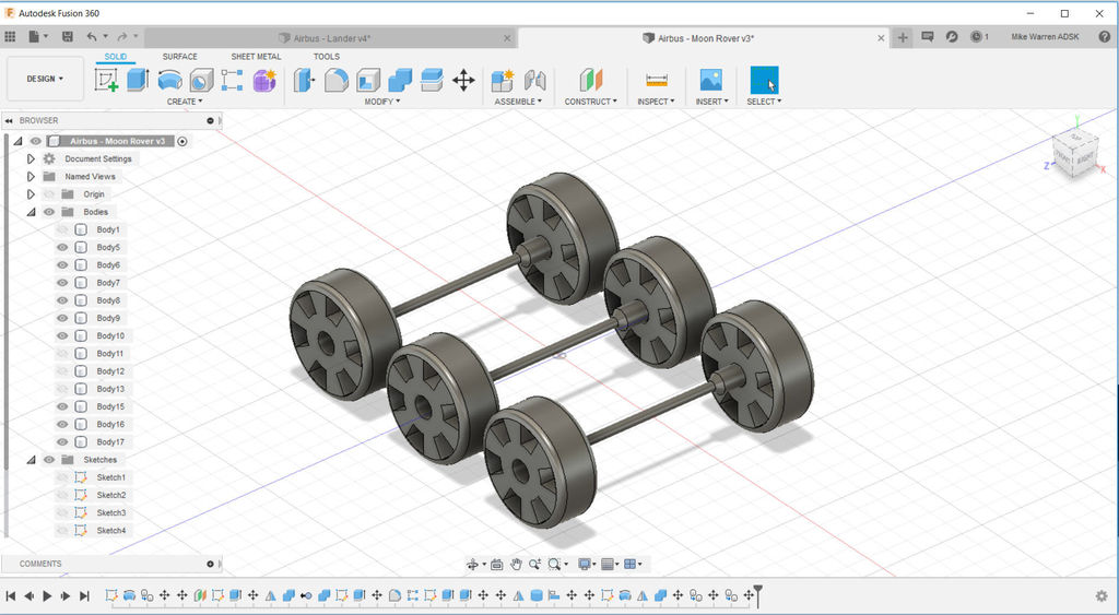
To make axles for the other wheels you can use the move/copy command, or the rectangular pattern command. Here is what my Rover axle and wheels look like.
Gears
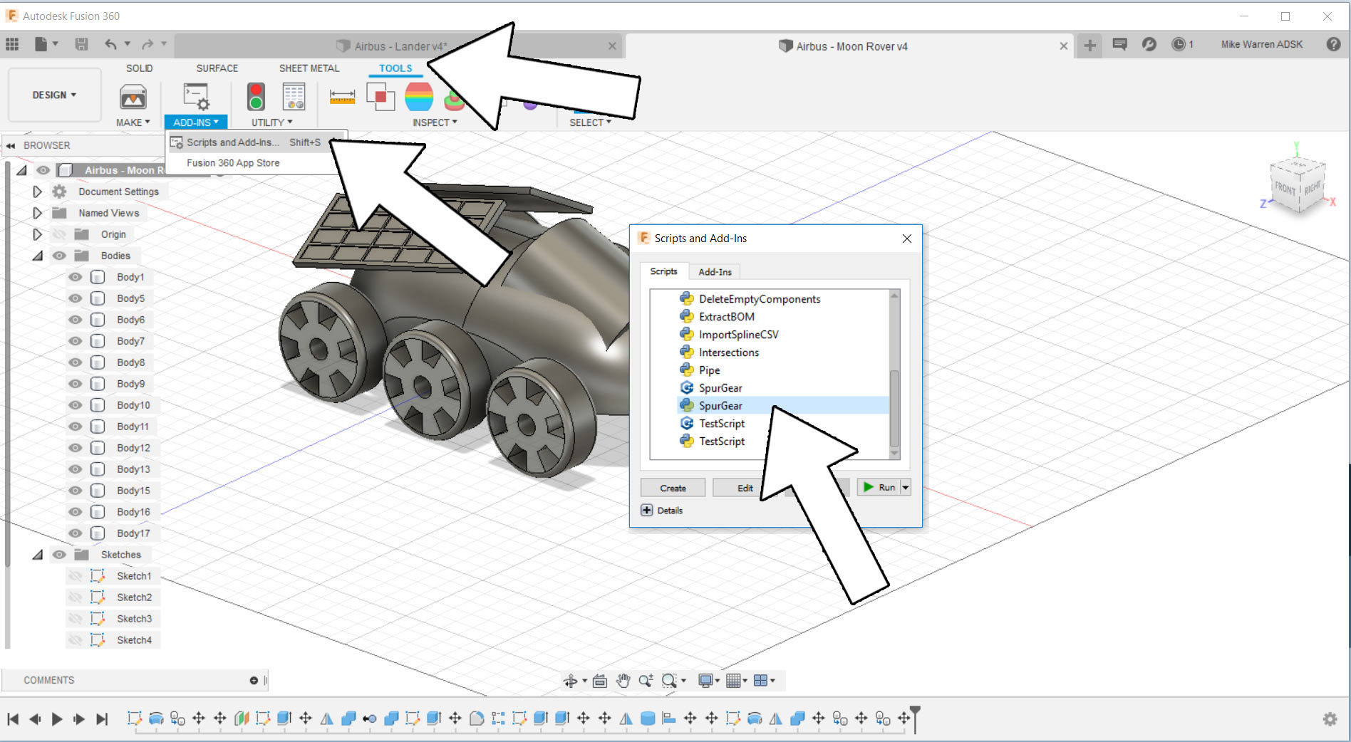
For some flair I added in a few exposed gears to my design. Fusion 360 has a gear generator built in, but needs to be turned on before you can use it.
In the top toolbar tools > add-ins > scripts and add-ins then scroll down to Spurgears, then click run.
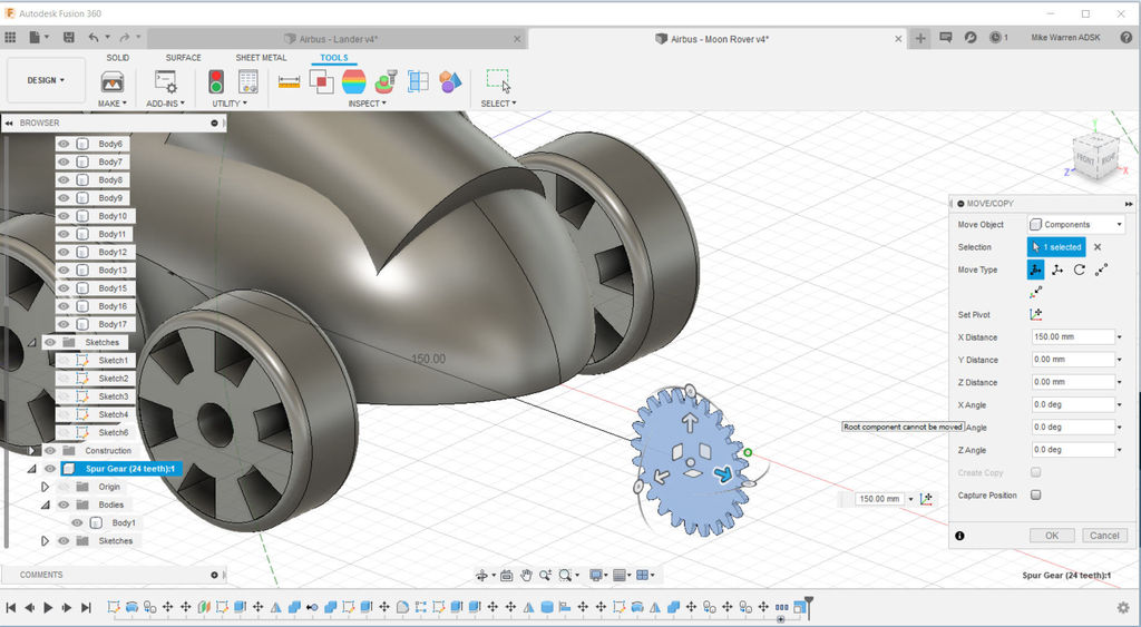
A gear will be placed on your work space, you cna then move it around to where you need it to go.
It's important to know that we're not using this gear in the way Fusion 360 intended. Fusion 360 is designed to work with gears like this to make functional assemblies, but we're using it as a non-functioning visual element.
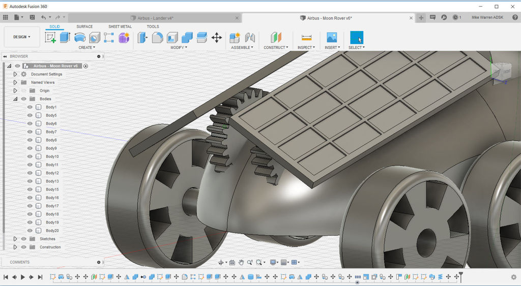
I tucked my gears under the solar panels to show my intention on how these panels could be operated.
Drill Appendage
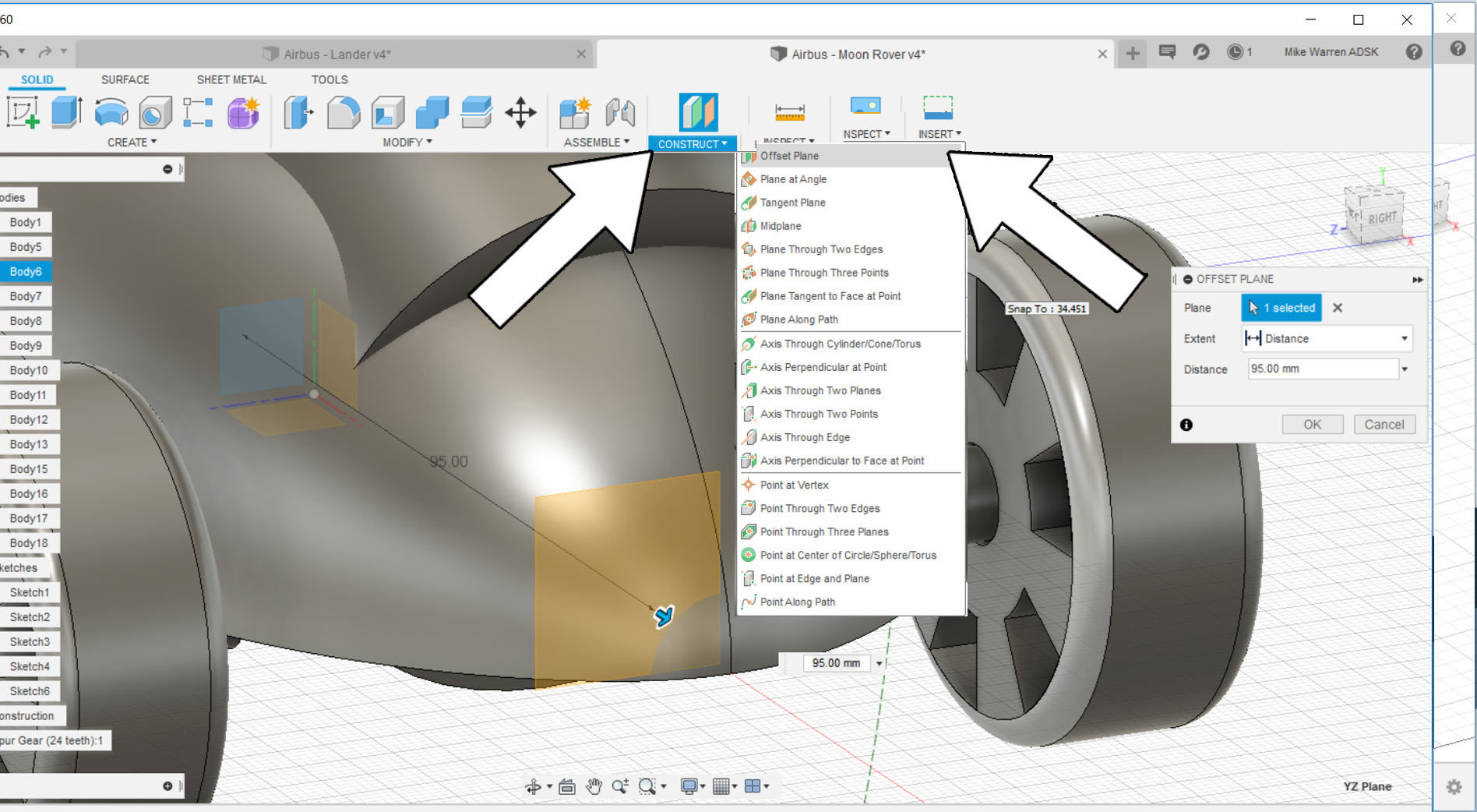
Our Moon Rover is almost complete. The last element I want to add is an arm that can have a drill or other tool attached.
To start we can make another offset plane to the front nose of the Rover.
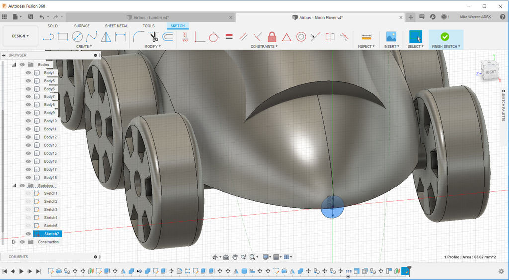
Start a new sketch and use the offset plane on the nose of the Rover as your plane. On the nose draw a small circle, this circle will be used as the shape for our appendage. Click finish sketch to complete this step, we'll make the appendage next using the circle as our shape guide.
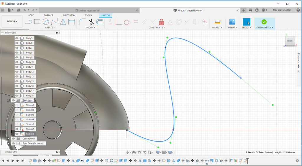
Start another new sketch on the profile of the Rover and create > spline to make an appendage profile extending from the nose of the Rover. When you're satisfied with your spline shape click finish sketch to return to the model environment.
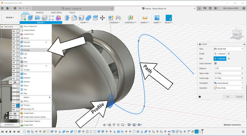
To make the appendage we can use the sweep command. The sweep menu will ask for a profile and path for the sweep. The circle we drew first on the nose will be the profile, and the spline sketch we drew second will be the path. Click OK to finish the command and see your appendage shape.
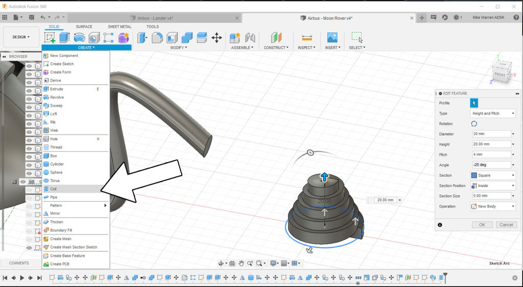
To make the drill representation I used create > coil, and then played with the coil settings to get a drill shape. You can use my settings in the image above as a reference.
The drill coil was then moved to the end of the appendage.
Appearance (optional)
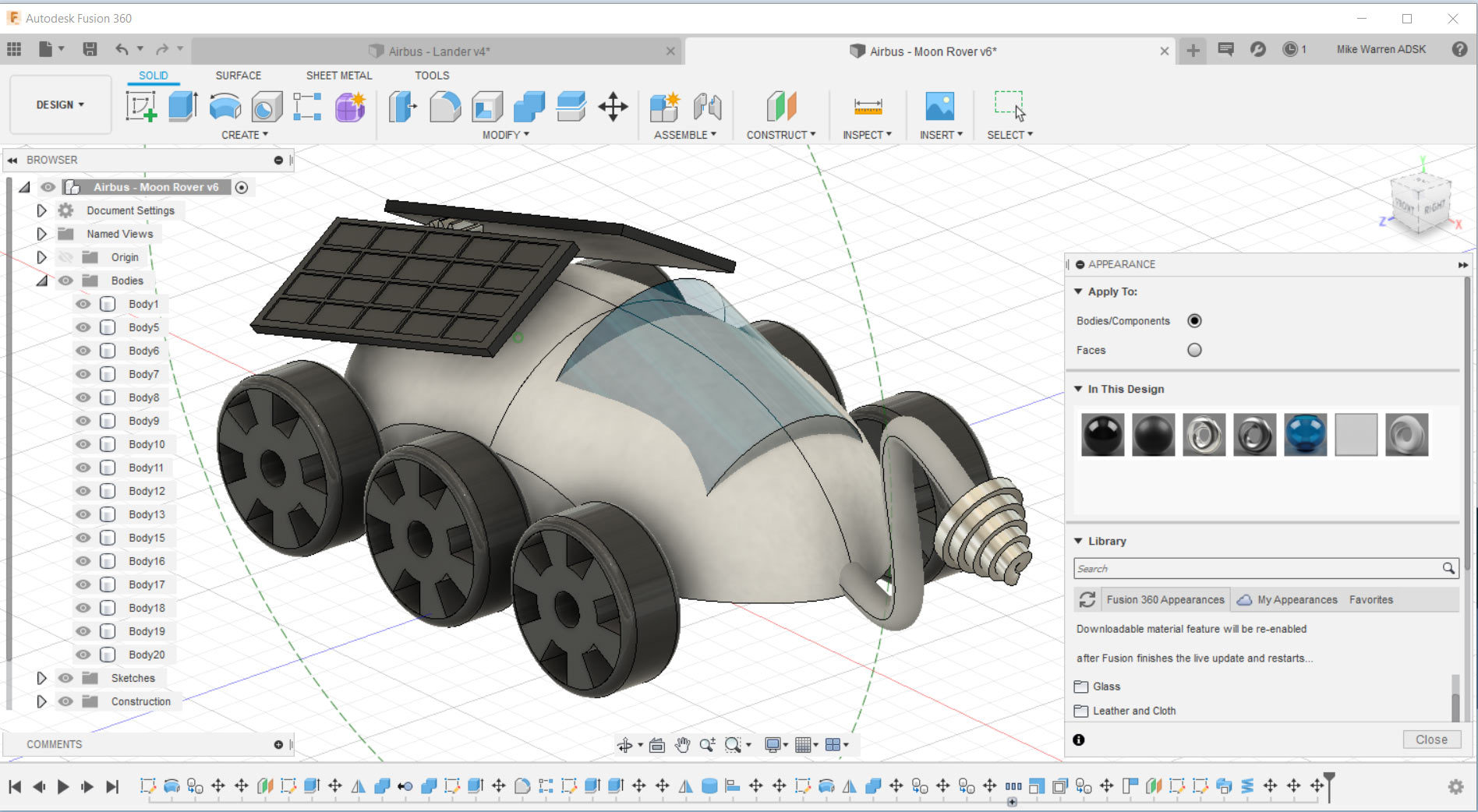
With the model finished we can turn our attention to the appearance. You can find a large library of materials under modify > appearance. In the appearance menu you can look in each folder for types of material, like metal or glass, and then drag the material of your choice onto the model body you want to have that appearance.
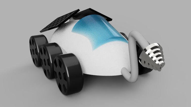
i used a blue glass for the cockpit, a matte black for the wheels, and a shiny black for the solar panels.
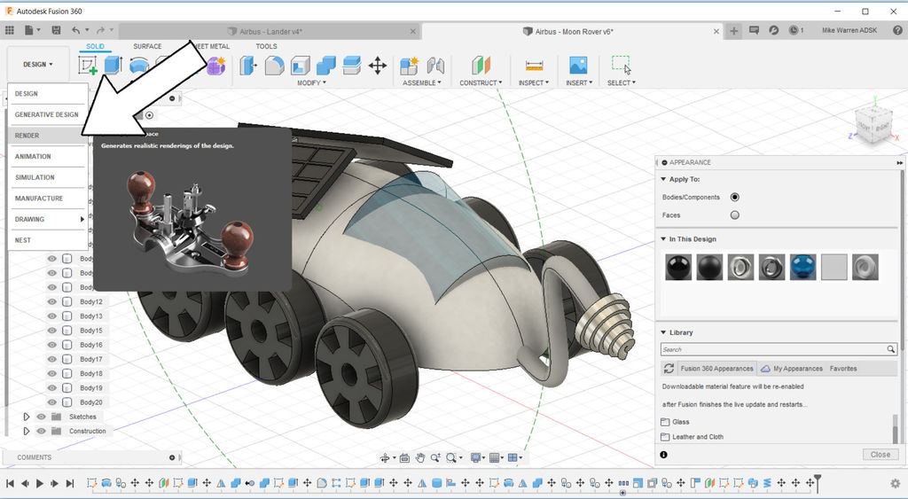
After applying materials we can render our model and see what it might look like outside of the CAD interface (without the grid background and all the toolbars). On the far left side of the screen you can see DESIGN, which is the workspace we've been working in. Click that to open a table of other workspacesand find RENDER.
You can render your model with a few preset backgrounds that Fusion 360 comes with, which are high dynamic range images (HDRI), or you can upload your own. Here's a website with free backgrounds (HDRIHaven.com)
Most of the stock backgrounds are a little boring, so I found one that looked like the desert for this Moon Rover.
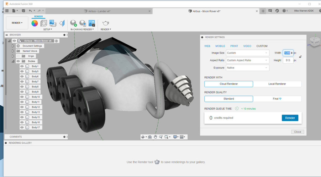
Find the standard render quality to generate a render of your design (it's free!). You can play with the settings here endlessly to create a perfect render of your Moon Rover. Below you can see my render.
When you are done, upload your Moon Rover designed in Fusion 360 in the comments below.
Happy making :)
Take Your Design to New Heights!
This tutorial was created as part of the Moon Camp Challenge, a yearly 3D design competition by the European Space Agency and the Airbus Foundation, in partnership with Autodesk.
If you're up for the challenge, head out to the competition platform here, find many other moon related 3D design tutorials and submit them to potentially win amazing prizes!